

World Dryer KJR-973K-1 Installation Manual
Airforce
(DOES NOT INCLUDE HAND DRYER)
KJR-973K-1
Recess Kit
Please read and save these instructions. Read carefully before attempting to assemble, install, operate or service
the product described. Protect yourself and others by observing all safety information. Failure to comply with
instructions could result in personal injury and/or property damage. Retain instructions for future reference.
World Dryer Corporation
5700 McDermott Drive
Berkeley, IL 60163 U.S.A.
800-323-0701
www.worlddryer.com
1
68-KJR-1 Rev01
Description
Stainless steel recessed wall box in brushed nish for installing Airforce warm air hand dryer – compliant with American
with Disabilities Act (ADA).
General Specications
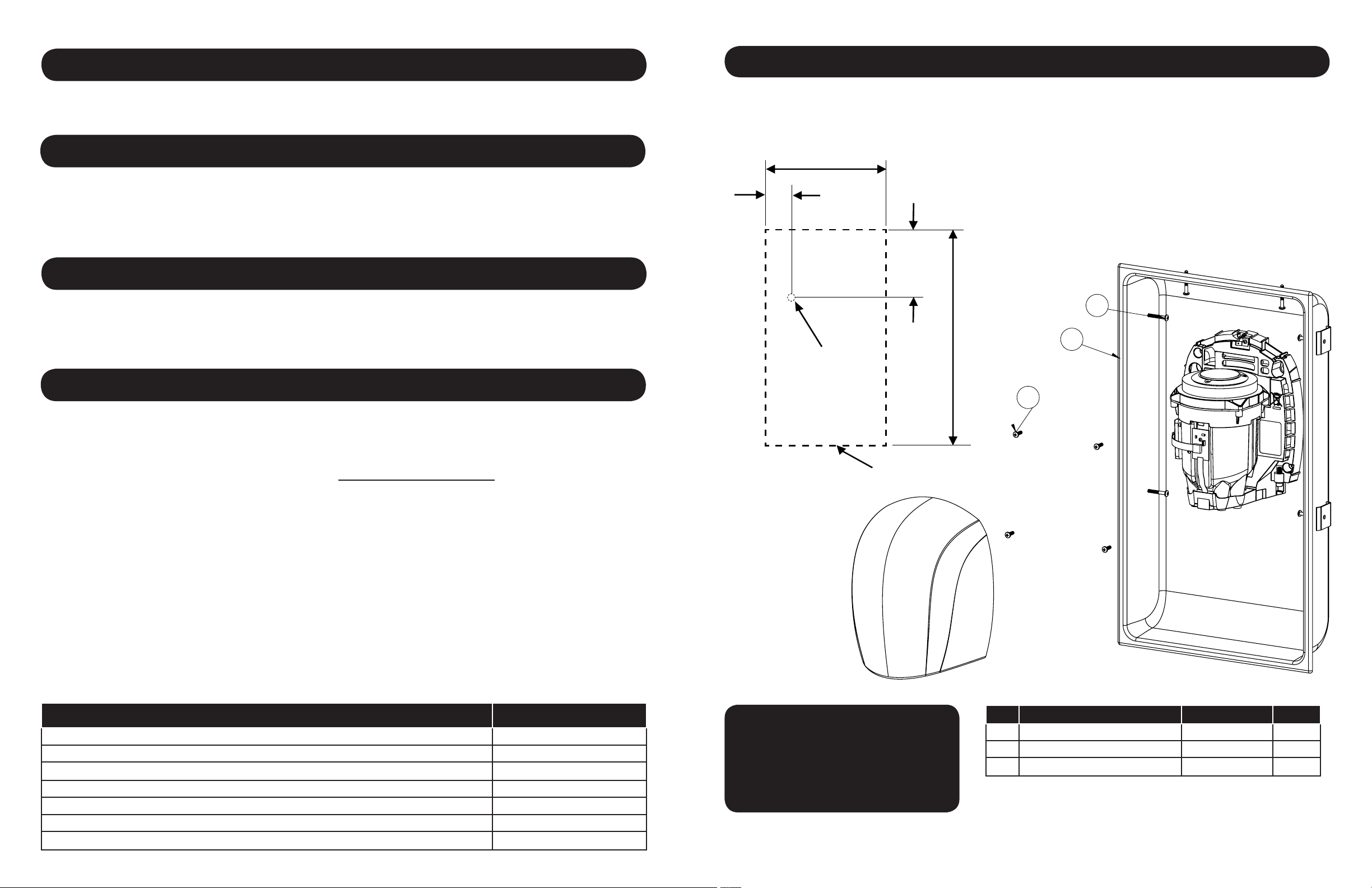
Parts List And Installation Diagram
Fig. 1
13 - 7/16”
Rough Opening
Material: AISI 304 Stainless Steel
Finish: Brushed
Dimensions W x H x D: 14-1/8 ” x 25 ”x 4-3/16 ” (35.9cm x 63.5cm x 10.6cm)
Weight: 10.3 lbs (4.7 Kg)
Unpacking
1. Remove all packing material. Recycling is recommended.
2. Carefully remove the wall box from the shipping carton.
3. Inspect for any damage that may have occurred during transit. If the wall box is damaged, promptly inform the dealer
where you purchased it.
Installation
A. Mounting the Wall Box
Refer to Fig. 1 “Parts List and Installation Diagram
1. Place the steel wall box in the wall at the desired location, having the lower edge of the box at the following heights
from the oor. (See Table 1). The rough opening for the wall box is 13-7/16”x 24-1/16”.
2. Allow opening in the wall to correspond with hole on the wall box in order to provide for easy access of conduit.
3. Mount wall box in the opening. Fasten wall box to stud with No. 10 wood screws. (Provided)
4. Run conduit from distribution panel to wall box. To limit voltage drop for efcient operation use AWG 12 wire or larger
as required by local electrical code.
3-3/16”
Electrical knock-out
Location
Outline -- Rough Opening
6-11/16”
24-1/16”
Rough Opening
2
1
3
Mounting Dryer in Wall Box
1. Disconnect the power source.
2. Use the security hex key supplied to turn the cover mounting screws clockwise to remove the cover from the dryer.
3. Place the hand dryer base on the wall box.
4. Fasten the base to the wall box, using provided #10-24 machine screws (4)
5. Connect the dryer to the power source.
6. Replace cover, turn screws counter-clockwise making certain not to over-tighten.
Table 1
Recommended Mounting Heights from Floor to Box Bottom Edge in. (cm.)
Men’s washrooms 37 (94)
Women’s washrooms 35 (89)
Children’s washrooms, ages 4-7 23.0 (58.5)
Children’s washrooms, ages 7-10 27.0 (68.5)
Children’s washrooms, ages 10-13 31.0 (78.5)
Children’s washrooms, ages 13-17 35 (89)
Handicap Mounting Height 28 (71)
For Repair Parts, visit www.WorldDryer.com
Please provide following information:
- Model number
- Serial number
- Part description and number shown in
parts list
Description Part Number Qty
#
1 Wall Box 17-10104 1
2 Wood Screw #10 46-93360 6
3 Machine Screw 46-90272 4
2
 Loading...