

World Dryer K-162 Installation Manual
SMARTdri
and SMARTdri
High-Efciency Intelligent Hand Dryer
Secamanos inteligente altamente eciente
Sèche-mains intelligent à haute efcacité
All K and K4 Series
Todos los modelos K y de la Serie K4
Ensemble de la série K et K4
™
plus
Please read and save these instructions. Read carefully before attempting to assemble, install, operate or service
the product described. Protect yourself and others by observing all safety information. Failure to comply with
instructions could result in personal injury and/or property damage. Retain instructions for future reference.
Por favor lea y guarde estas instrucciones. Léalas cuidadosamente antes de tratar de montar, instalar, operar o dar mantenimiento al producto aquí
descrito. Protéjase usted mismo y a los demás observando toda la información de seguridad. No seguir las instrucciones puede ocasionar daños, tanto
personales como materiales. Guarde estas instrucciones para referencia en el futuro.
Lire et conserver ces instructions. Les lire attentivement avant de commencer à assembler, installer, faire fonctionner, réparer ou entretenir l’appareil
décrit. Pour se protéger et protéger autrui, observer toutes les consignes de sécurité. Le fait de négliger d’appliquer ces instructions peut entraîner des
blessures et/ou des dommages matériels. Conserver ces instructions pour consultation ultérieure.
World Dryer Corporation
5700 McDermott Drive
Berkeley, IL 60163 U.S.A.
800-323-0701
www.worlddryer.com
1
Description
World warm air hand dryer, powered by a universal brush motor, delivers up to 850 watts of drying power and incorporates
an integrated element for heated air. The dryer controls provide for (3) distinct levels of motor operation (Hi, Med and
Low) and the option of operation with, or without, the heating element. An infrared sensor is used to automatically activate
the dryer. These models are intended for use in commercial, industrial, ofce and public facility environments.
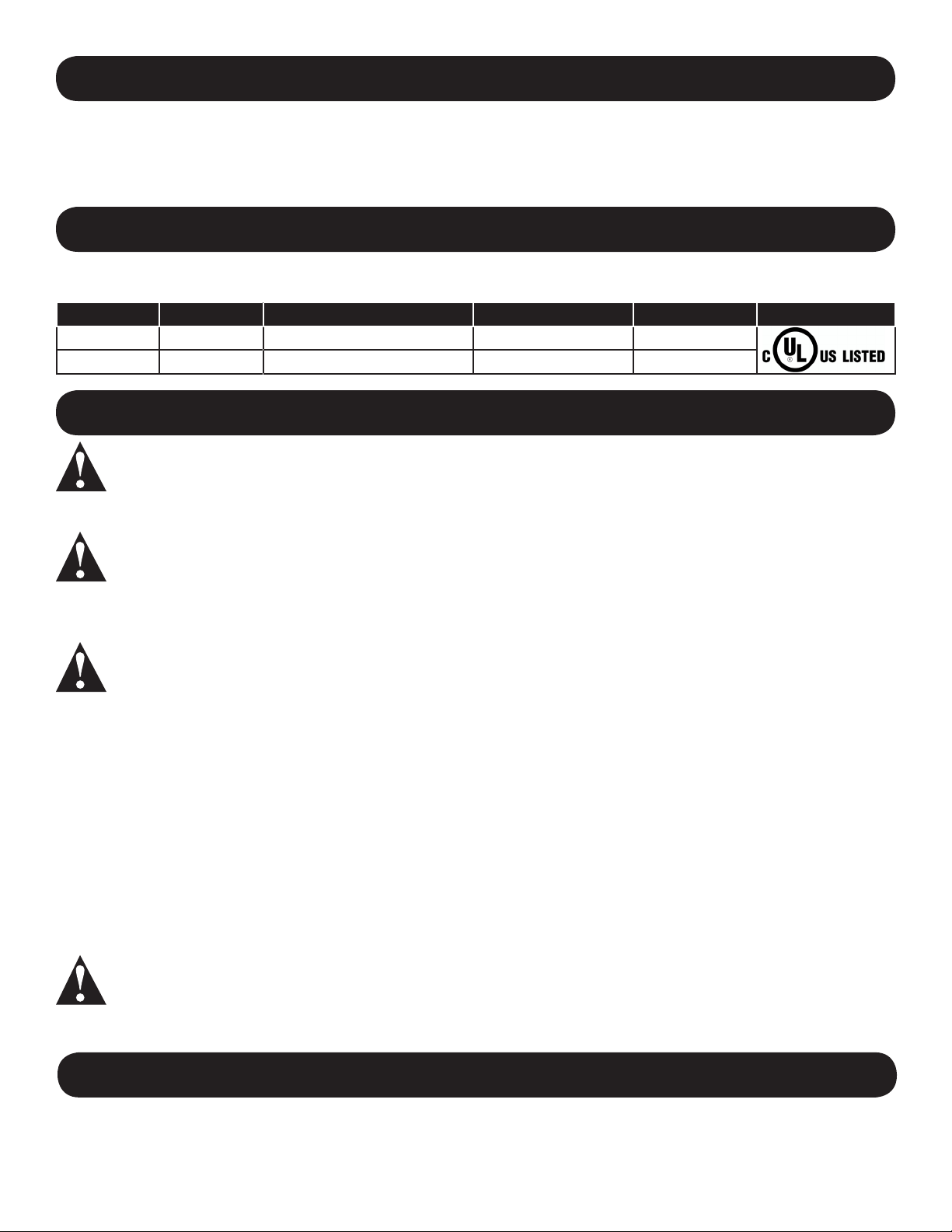
Electrical Specications
Table 1
Models Type Electrical Input Rated Amperage Rated Watts Certications
K-XXX Automatic 120VAC, 50/ 60Hz 10A 1200 UL
K4-XXX Automatic 208 - 240VAC, 50/60Hz 5.2A 1250 UL
General Safety Information
DANGER Failure to disconnect the power source before installation or servicing can result in serious
injury or death from electric shock.
• Always disconnect the power source before servicing or installing the hand dryer.
DANGER Failure to properly ground this unit could result in severe electrical shock and/or death.
• This hand dryer must be properly grounded (Earthed) for safe operation. An identied ground connection point is
supplied on the hand dryer’s wall base.
• We recommend GFCI protection in wet or damp locations or as required by local code.
WARNING Risk of re, personal injury or property damage are possible if local codes, or safety
recommendations are not followed.
• Installation and servicing should only be performed by qualied electrical technicians.
• Use only the electrical power (voltage and frequency) specied for the model hand dryer being installed. See Table 1 Electrical Specications.
• Connect the hand dryer to the nearest suitable distribution panel.
• To limit a voltage drop, and insure efcient operation, use No. 12 AWG (4 mm2) wire or larger as required by local
electrical codes.
• Always connect to a branch circuit with circuit breaker or fuse protection with an electrical rating greater than the model
hand dryer’s rated amperage shown in Table 1 - Electrical Specications in accordance with the NEC (National Electrical
Code) and/or CEC (Canadian Electrical Code).
• To avoid a hazard due to inadvertent resetting of the thermal cutout, the hand dryer must not be supplied through an
external switching device, such as a timer, or connected to a circuit that is regularly switched on and off by the utility.
• Each automatic model hand dryer must have a dedicated circuit.
• Route all eld wiring away from moving parts within the hand dryer.
CAUTION Improper mounting could result in personal injury or property damage.
• Follow the mounting height recommendations in Table 2.
• On a stud wall, one side of the hand dryer should be mounted to an existing stud.
Unpacking
1. Remove all packing material. Recycling is recommended.
2. Carefully remove the hand dryer from the shipping carton, using care not to drop the appliance.
3. Inspect carefully for any damage that may have occurred during transit. Check for any loose, missing or damaged
parts. If the hand dryer is damaged, promptly inform the dealer where you purchased it.
2
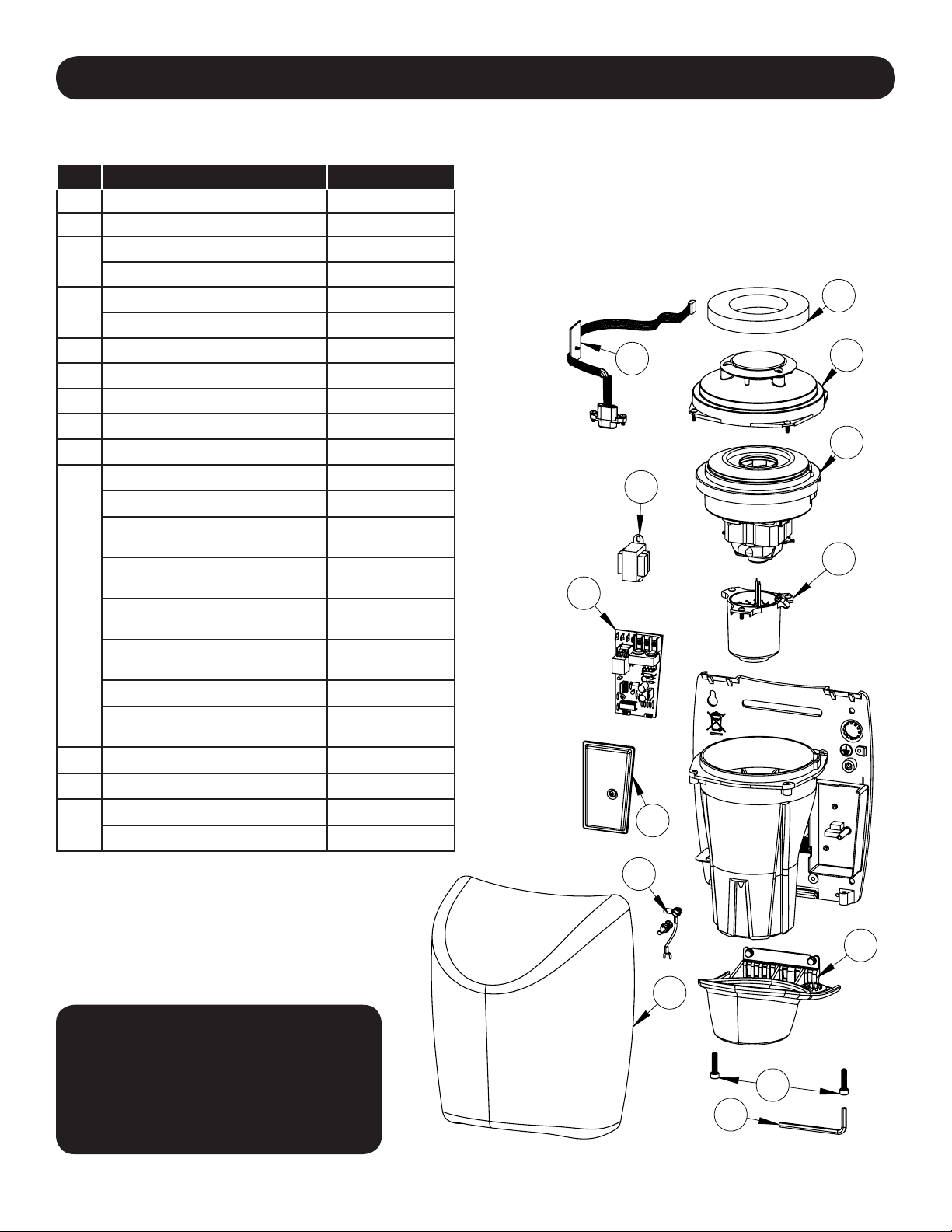
Parts List
Repair Parts List For SMARTdri™ and SMARTdri Plus Hand Dryers
Description Part Number
#
1 Kit, Sensor 49-10108K
2 Kit, Dryer Controls 16-KK
Kit, Motor- 120V 32-K120K
3
Kit, Motor - 240V 32-K240K
Kit, Heating Element - 120V 21-1120K
4
Kit, Heating Element - 240V 21-1240K
5 Kit, Plenum Cap Assy 47-0818092AK
6 Air Filter 93-120309
7 Kit, Controls Cover 20-0815093K
8 Kit, Nozzle 30-K10109K
9 Kit, Grounding - Model K 23-120609
Cover Assy - Alum - White 20-K974
Cover Assy - Alum - Black 20-K162
Cover Assy - Alum - Polished/
Bright Chrome
Cover Assy - Alum - Brushed/
Satin Chrome
10
Cover Assy - Stainless Steel -
Polished/ Bright
Cover Assy - Stainless Steel -
Brushed/ Satin
Cover Assy - Steel - White 20-K975
Cover Assy - Cast Iron - Porce-
lain Enamel
11 Kit, Security Screws 46-040222K
12 Wrench, Security 56-40189
Transformer - 120V 50-K120K
13
Transformer - 240V 50-K277K
20-K970
20-K971
20-K972
20-K973
20-K976
2
1
13
7
6
5
3
4
All kits include fasteners needed for
installation.Part Number for Cover Assy.
(Reference Number 10) varies with model
number for hand dryer.
For Repair Parts, visit www.WorldDryer.com
Please provide following information:
- Model number
- Serial number
- Part description and number shown in
parts list
9
8
10
11
12
3
Installation
1. Disconnect the power source.
2. Using Table 2 to determine the recommended mounting height, select a mounting location for the hand dryer where
no reective surfaces or objects (such as a hand basin) are directly under the infra-red sensor eye. The infra-red
sensor eye is visible from the bottom of the dryer and is located just inside the dryer’s nozzle area. The minimum
mounting distance from bottom of the dryer to a reective surface is 18 in (46 cm). When two or more dryers are
installed, they should be spaced apart 24 in (61 cm)
3. Use the security hex key supplied to turn the cover mounting screws clockwise to remove the cover from the dryer.
4. Place the hand dryer base on the wall at selected location and using the base as a template, mark locations for the 4
mounting bolt holes on the wall.
5. Fasten the base to the wall, using the type of bolts recommended in Table 3
6. Each dryer must have is own dedicated circuit.
7. Connect the dryer to the nearest suitable distribution panel.
8. Replace cover, turn screws counter-clockwise making certain not to over-tighten.
IMPORTANT: Consult local and general regulations before performing dryer installation. Ensure the electrical
network is not overloaded. Always connect to a dedicated branch circuit with circuit breaker or fuse protection and
an electrical rating greater than the model hand dryer’s rated amperage shown in Table 1 - Electrical Specications in
accordance with the NEC (National Electrical Code) and/or CEC (Canadian Electrical Code).
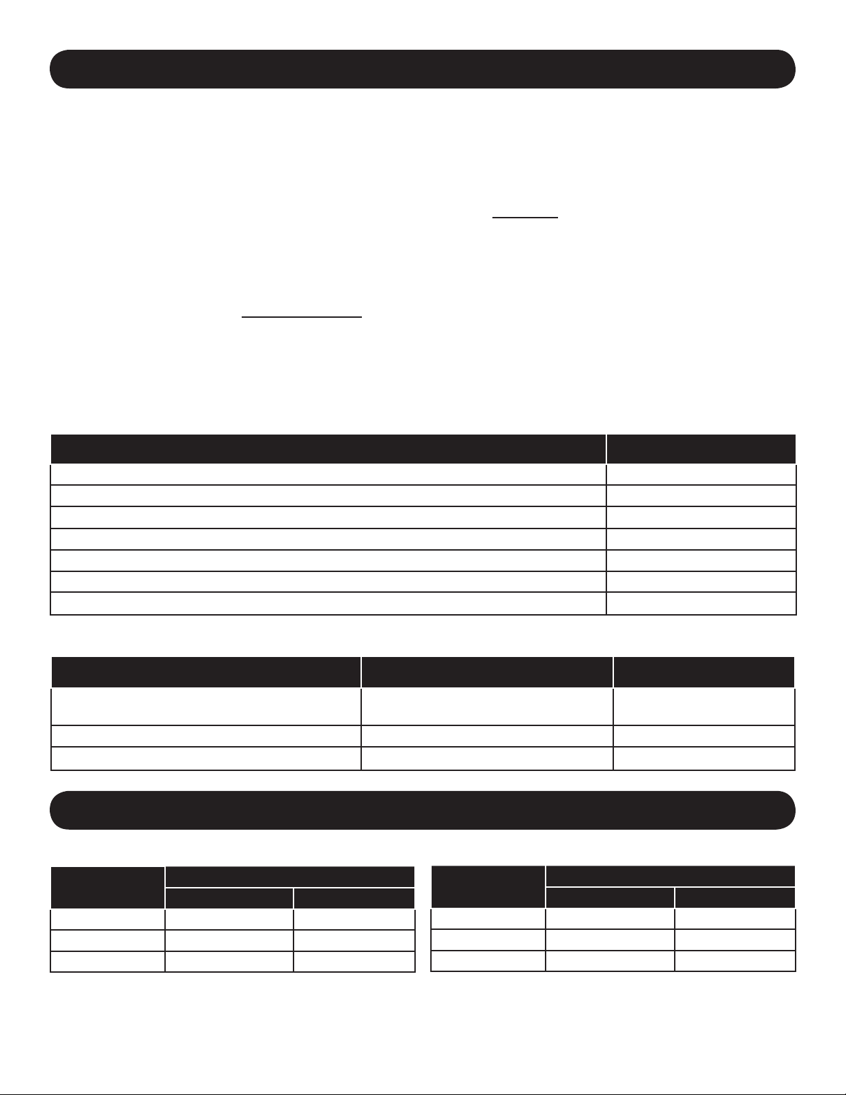
Table 2
Recommended Mounting Heights from Floor to Dryer Bottom Edge in. (cm.)
Men’s washrooms 46 (117)
Women’s washrooms 44 (112)
Children’s washrooms, ages 4-7 32 (81)
Children’s washrooms, ages 7-10 36 (91)
Children’s washrooms, ages 10-13 40 (102)
Children’s washrooms, ages 13-17 44 (112)
Handicap Mounting Height 37 (94)
Table 3
Type of Wall Type of Bolt Minimum Bolt Length
Hollow Tile, Lath, Wall Board or Metal
Cement, Brick, or Tile Covered Cement or Brick 1/4” (M6) Stud Type Expansion Bolts 3” (76mm)
Stud Wall with wood Backing No 16 (M8) Wood Screws 23/4” (70mm)
1/4” (M6) screw Type or Wing Type
toggle Bolts
Dependent on wall
thickness
Adjusting Dryer Controls
Table 4
Motor Setting
Hi 800 1200
Med 575 975
Low 400 800
The hand dryer has adjustable controls for (3) levels of operation – Hi, Med and Low. The dryer can be operated with
the heating element “ON” or “OFF”. The dryer’s power usage for the range of operation is shown in Table 4.
Note: The factory setting for the dryer controls is motor “Hi” and heater “ON”.
K-XXX Series Models
Power Usage (Watts)
Heater "OFF" Heater “ON”*
Motor Setting
Hi 850 1250
Med 600 1000
Low 425 825
4
K4-XXX Series Models
Power Usage (Watts)
Heater "OFF" Heater “ON”*
* Heating element wattage is 400W maximum.
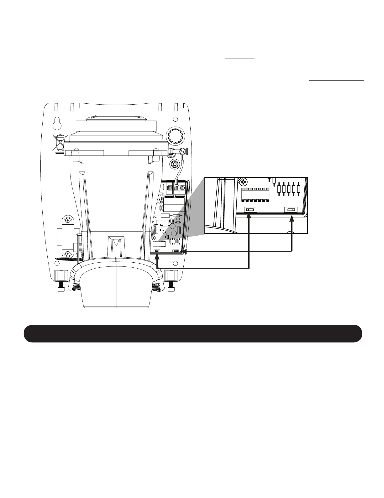
The adjustable dryer controls are located on the printed circuit board inside the dryer’s wiring compartment.
To adjust dryer controls:
1. Disconnect the power source.
2. Use the security hex key supplied to turn the cover mounting screws clockwise to remove the cover from the dryer.
3. Remove the wiring compartment cover to access the adjustable controls (see Fig. 1).
4. Adjust motor setting and heater as desired, and replace wiring compartment cover.
5. Reassemble the dryer cover using the security hex key supplied to turn the cover mounting screws counter-clockwise
and tighten until snug. Do not over tighten.
Fig. 1
Heater Options
On / Off
Motor Settings
Hi / Med / Low
Maintenance and Cleaning Instructions
IMPORTANT: The dryer has an air lter to prevent lint and debris build up that can damage the motor and
heating element. Routine replacement or cleaning of the air lter is needed to maintain the dryer in good
operating condition. With light to moderate wash room trafc, replacing or cleaning the air lter once a year is
recommended. If the wash room trafc is high, the air lter should be replaced or cleaned every 6 months. Read
complete instruction before proceeding.
To replace or clean the air lter:
1. Disconnect the power source.
2. Use the security hex key supplied to turn the cover mounting screws clockwise to remove the cover from the dryer.
3. Removing and replacing the air lter is easily done by gently stretching and lifting the air lter around the motor inlet
cover.
4. To clean the air lter, remove from motor inlet cover. Use soft-medium bristle ½” paint brush to clean lint, dust and
debris from the lter. If air lter cannot be completely cleared of debris, replace the lter.
5. After replacing the air lter onto the motor inlet cover, reassemble the dryer cover using the security hex key supplied to
turn the cover mounting screws counter-clockwise and tight until snug. Do not over tighten.
5
 Loading...