

Page 1
Airforce
High Efciency Hand Dryer
Secamanos altamente eciente Sèche-mains à haute efcacité
All J & J4 Series
Todos los de la serie J4 y J4
Ensemble de la série J4 et J4
Please read and save these instructions. Read carefully before attempting to assemble, install, operate or service the product described.
Protect yourself and others by observing all safety information. Failure to comply with instructions could result in personal injury and/or
property damage. Retain instructions for future reference.
Por favor lea y guarde estas instrucciones. Léalas cuidadosamente antes de tratar de montar, instalar, operar o dar mantenimiento al producto aquí descrito. Protéjase usted mismo y a los demás
observando toda la información de seguridad. No seguir las instrucciones puede ocasionar daños, tanto personales como materiales. Guarde estas instrucciones para referencia en el futuro.
Lire et conserver ces instructions. Les lire attentivement avant de commencer à assembler, à installer, à faire fonctionner ou à entretenir l’appareil décrit. Pour se protéger et protéger autrui,
observer toutes les consignes de sécurité. Négliger de se conformer à ces instructions peut causer des blessures personnelles et/ou des dommages matériels. Conserver ces instructions pour
références ultérieures.
World Dryer Corporation
5700 McDermott Drive
Berkeley, IL 60163 U.S.A.
800-323-0701
www.worlddryer.com
1
Page 2
Description
World warm air hand dryer, powered by universal brush motor, delivers 1100 Watts of drying power. This hand dryer runs
on 120 Volt or 208-240 Volt AC electrical supply depending on model. An infrared sensor is used to automatically turn the
dryer on and off. This model is intended for use in commercial, industrial, ofce and public facility environments.
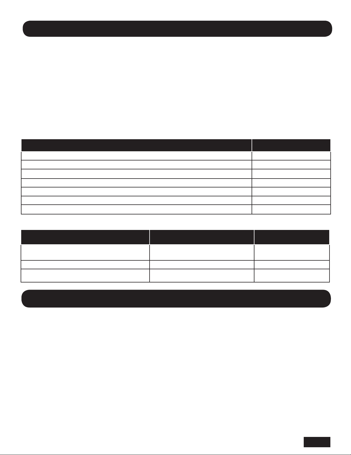
Electrical Specications
Table 1
Models Type Electrical Input Rated Amperage Rated Watts Certications
J-XXX Automatic 120 VAC, 50/60Hz 9.6A 1100 UL, E320188
J4-XXX Automatic 208-240 VAC, 50/60Hz 4.8A 1100 UL, E320188
General Safety Information
This appliance is not intended for use by young children or persons with physical, sensory or mental disabilities
unless adequately supervised by a responsible person to ensure they can use the appliance safely. Young children
should be supervised to ensure they do not play with the appliance.
DANGER Failure to disconnect the power source before installation or servicing can result in serious
injury or death from electric shock.
• Always disconnect the power source before servicing or installing the hand dryer.
DANGER Failure to properly ground this unit could result in severe electrical shock and/or death.
• This hand dryer must be properly grounded (Earthed) for safe operation. An identied ground connection point
is supplied on the hand dryer’s wall base.
• We recommend GFCI protection in wet or damp locations or as required by local code.
WARNING Risk of re, personal injury or property damage are possible if local codes, or safety
recommendations are not followed.
• Use only the electrical power (voltage and frequency) specied for the model hand dryer being installed. See
Table 1 – Electrical Specications.
• Connect the hand dryer to the nearest suitable distribution panel. The xed wiring must include a disconnection
means complying with local wiring codes.
• To limit a voltage drop, and insure efcient operation, use No. 12 AWG (4 mm2) wire or larger as required by
local electrical codes.
• Always connect to a branch circuit with circuit breaker or fuse protection with an electrical rating greater than the
model hand dryer’s rated amperage shown in Table 1 - Electrical Specications.
• To avoid a hazard due to inadvertent resetting of the thermal cutout, the hand dryer must not be supplied
through an external switching device, such as a timer, or connected to a circuit that is regularly switched on and off by
the utility.
• Each automatic model hand dryer must have a dedicated circuit.
• Route all eld wiring away from moving parts within the hand dryer.
CAUTION Improper mounting could result in personal injury or property damage.
• Follow the mounting height recommendations in Table 2.
• On a stud wall, one side of the hand dryer should be mounted to an existing stud.
Unpacking
1. Remove fuse or shut off power to the dryer at fuse box.
2. With Allen wrench supplied with dryer, turn clockwise two Allen screws from bottom side of dryer case.
3. Remove dryer cover.
English
2
Page 3
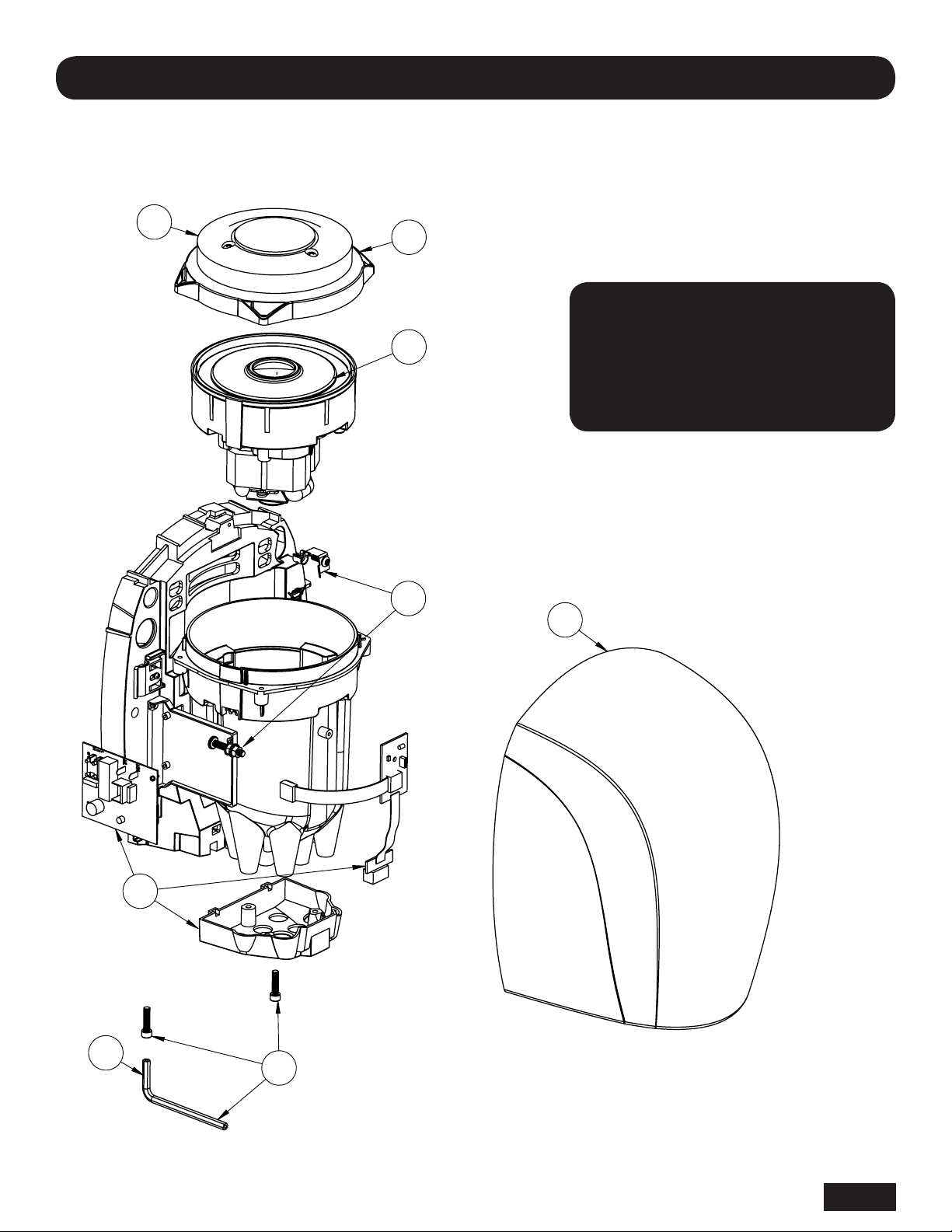
Parts List
Repair Parts List For Airforce Hand Dryers
4
3
1
5
All kits include fasteners needed for
installation.
For Repair Parts, visit www.WorldDryer.com
Please provide following information:
- Model number
- Serial number
- Part description and number shown in
parts list
8
2
7
6
3
English
Page 4
#
"
"
1a Motor, 120 V, Model J 32-J120K 1
1b Motor, 240 V, Model J4 32-J240K 1
2 Electronics Kit (All voltage models) 16-10361K 1
3 Kit, Plenum Cap 47-120309K 1
4 Filter, Air Intake 93-120309 1
5 Kit, Grounding 52-030244K 1
6 Tamper-resistant Cover Screws and Wrench 46-040221K 2
7 Wrench 56-40189 1
8a Cover, Alum, White 20-243-974JK 1
8b Cover, Alum, Chrome, Polished 20-243-970JK 1
8c Cover, Alum, Chrome, Brushed 20-243-971JK 1
8d Cover, Alum, Black 20-243-162JK 1
8e Cover. Steel. White 20-243-975JK 1
8f Cover, Stainless Steel, Polished 20-243-972JK 1
8g Cover, Stainless Steel, Brushed 20-243-973JK 1
Description Part Number Qty
All kits include fasteners needed for installation.
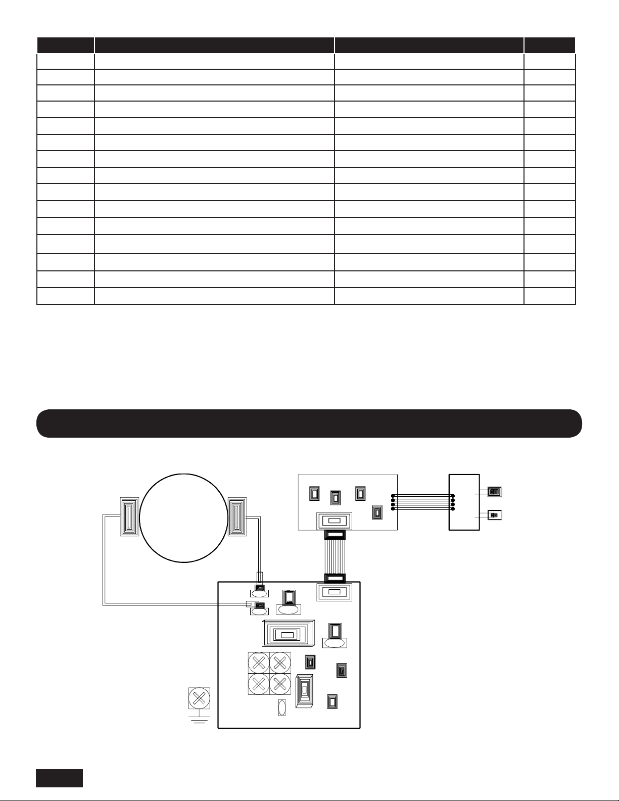
Wiring Diagram
Motor
MN
ML
J" Model - 120VAC
J4" Model - 208-240 VAC
1 2 3 4 5
1 2 3 4 5
L1
L2/N
GRND
English
4
Page 5
Installation
1. Disconnect the power source.
2. Use the security hex key supplied to turn the cover mounting screws clockwise to remove the cover from the dryer.
3. Place the hand dryer base on the wall at the desired location using Table 2 to determine the recommended mounting
height. With the base so located, use it as a template to mark locations of the 4 mounting bolt holes on the wall.
Ensure that no reective object (such as a hand basin) is located directly under infra-red sensor eye; the minimum
distance is 18 inches (46 cm).
4. Fasten the base to the wall, using the type of bolts suggested in Table 3.
5. All automatic dryers must have their own dedicated 10 amp circuit.
6. Connect the dryer to the nearest suitable distribution panel.
7. Replace cover, turn screws counter-clockwise making certain not to over-tighten.
IMPORTANT: Consult local and general regulations before performing dryer installation. Ensure that the
electrical network is not overloaded. Do not connect to a branch circuit over 10 amps.
Table 2
Recommended Mounting Heights from Floor to Dryer Bottom Edge in. (cm.)
Men’s washrooms 46 (117)
Women’s washrooms 44 (112)
Children’s washrooms, ages 4-7 32 (81)
Children’s washrooms, ages 7-10 36 (91)
Children’s washrooms, ages 10-13 40 (102)
Children’s washrooms, ages 13-17 44 (112)
Handicap Mounting Height 37 (94)
Table 3
Type of Wall Type of Bolt Minimum Bolt Length
Hollow Tile, Lath, Wall Board or Metal
Cement, Brick, or Tile Covered Cement or Brick 1/4” (M6) Stud Type Expansion Bolts 3” (76mm)
Stud Wall with wood Backing No 16 (M8) Wood Screws 23/4” (70mm)
1/4” (M6) screw Type or Wing Type
toggle Bolts
Dependent on wall
thickness
Maintenance and Cleaning Instructions
Maintenance
1. Remove fuse or shut off power to the dryer at fuse box.
2. With Allen wrench supplied with dryer, turn clockwise two Allen screws from bottom side of dryer case.
3. Remove dryer cover.
Cleaning Instructions
Read complete instruction before proceeding. Under normal use, cleaning the Dryer once a year will keep it in good
operating condition. If the washroom trafc is heavier than normal, the cleaning should be done every 6 months. Lint and
dust build up inside the dryer can result in damage to motor.
1. Turn off dryer at circuit breaker or fuse panel.
2. Turn clockwise two cover mounting screws from dryer cover using security hex key provided. Support cover while
removing screws.
3. Vacuum out dirt from blower and housing. Use caution not to damage wires or circuit boards.
4. The motor inlet cover may be removed by unscrewing the (4) screws. This allows access to the motor for cleaning or
replacement.
5. Use soft-medium bristle ½” paint brush to clean dust and dirt from motor.
6. Replace cover. Place cover squarely over base and push ush to wall. Turn cover mounting screws counter-clockwise
and tighten until snug. Do not over tighten.
5
English
Page 6

Troubleshooting Chart
Sensor obstruction
Dryer fails to start.
Dryer will not shut off
or runs 20-30 seconds,
then will not re-start
Dryer “Ghosts” starts
with no hands present
Motor noisy or vibrates
Dryer air too hot
No power to the unit Check if power is “ON”; Check electrical connections
Faulty Circuit Board and Sensor Listen for PCB Relay “Click”; If no “Click” is heard, replace the PCB and Sensor
Faulty Motor If Relay “Click” is heard, but unit does not start, replace the Motor / Fan assembly
Sensor obstruction
Sensor receiving false signal or
reection
Fluctuating power supply
Dryer mount on wall loose
Faulty Motor and Fan Replace Motor and Fan Assembly
Air intake blocked
Dirty air lter
1. Check Sensor Lens for foreign material or dirt. Clean lens with soft damp
cloth and mild cleaning agent
2. If Lens is damaged or scratched, replace it
1. Check Sensor Lens for foreign material or dirt. Clean Lens with soft damp
cloth and mild cleaning agent
2. If Lens is damaged or scratched, replace it
1. Hand Dryer should be mounted a minimum of 18” above a reective surface
2. Check if other Infrared operated appliances in the vicinity may be triggering
the Dryer
3. Replace the PCB and Sensor
1. Multiple Hand Dryers on one circuit or Dryers sharing a lighting circuit.
Automatic Hand Dryers must be on dedicated circuits
2. Building wiring may be insufcient gauge or too long of a run from the supply
Check if mounting screws are tight and dryer is solid to wall
Inspect for and remove foreign material blocking air intake slots. Using a soft
brush and vacuum, clean intake slots
Clean or replace air lter. To clean, remove and use a soft brush and vacuum to
remove all foreign material. If air lter cannot be completely cleaned, replace it
Limited Warranty
World LIMITED FIVE– YEAR WARRANTY. World dryer™ warm air hand dryers, covered in this manual, are warranted by world dryer corporation to the
original owner against defects in workmanship or materials under normal use for ve years and three years for electronic controls after the date of purchase. Normal
wear or abuse of any component is excluded from this warranty. Any part which is determined to be defective in material or workmanship and returned, shipping costs
prepaid, will be, as the exclusive remedy, repaired or replaced at world’s option. For limited warranty claim procedures, see “prompt disposition” below. This limited
warranty gives purchasers specic legal rights which vary from jurisdiction to jurisdiction.
LIMITATION OF LIABILITY. To the extent allowable under applicable law, World’s liability for consequential and incidental damages is expressly disclaimed.
World’s liability in all events is limited to and shall not exceed the purchase price paid.
WARRANTY DISCLAIMER. World has made a diligent effort to provide product information and illustrate the products in this literature accurately; however,
such information and illustrations are for the sole purpose of identication, and do not express or imply a warranty that the products are MERCHANTABLE, or FIT FOR
A PARTICULAR PURPOSE, or that the products will necessary conform to the illustrations or descriptions. Except as provided below, no warranty or afrmation on
fact, expressed or implied, other than as stated in the “LIMITED WARRANTY” above is made or authorized by World.
PRODUCT SUITABILITY. Many jurisdictions have codes and regulations governing sales, construction, installation, and/or use of products for certain purposes,
which may vary from those in neighboring areas. While World attempts to assure that the products comply with such codes, it cannot guarantee compliance, and cannot be responsible for how the product is installed or used. Before purchase and use of a product, review the product application, and all applicable national and local
codes and regulations, and be sure that the product, installation, and use will comply with them.
Certain aspects of disclaimers are not applicable to consumer products; e.g., (a) some jurisdictions do not allow the exclusion or limitation of incidental or consequential damages, so the above limitation or exclusion may not apply to you; (b) also, some jurisdictions do not allow a limitation on how long an implied warranty lasts,
consequentially the above limitation may not apply to you; and (c) by law, during the period of this Limited Warranty, and implied warranties of implied merchantability
or tness for particular purpose applicable to consumer products purchased by consumers, may not be excluded or otherwise disclaimed.
Manufactured by World Dryer Corporation, Berkeley, Illinois 60163 U.S.A.
PROMPT DISPOSITION. World will make a good faith effort for prompt correction or other adjustment with respect to any product which proves to be defective
within limited warranty. For any product believed to be defective within limited warranty, rst write or call dealer from whom the product was purchased. Dealer will
give additional directions. If unable to resolve satisfactorily, write to World at address below, giving dealer’s name, address, date, and number of dealer’s invoice, and
describing the nature of defect. Title and risk of loss pass to buyer on delivery to common carrier. If product was damaged in transit to you, le claim with carrier.
5700 McDermott Drive
Berkeley, IL 60163 U.S.A.
800-323-0701
6
www.worlddryer.com
Page 7

Descripción
El secamanos por aire caliente World, impulsado por motor universal con escobillas, suministra 1100 vatios de potencia
de secado. Este secamanos funciona con un suministro eléctrico de 120 voltios de CA, o 208-240 voltios de CA,
dependiendo del modelo. El secamanos se enciende y apaga automáticamente mediante un sensor de infrarrojos. Este
modelo está diseñado para entornos comerciales, industriales, de ocinas e instalaciones públicas.
Especicaciones del sistema eléctrico
Tabla 1
Modelos Tipo Entrada eléctrica Amperaje nominal Vatios nominales Certicaciones
J-XXX Automático 120 VAC, 50/60Hz 9.6A 1100 UL, E320188
J4-XXX Automático 208-240 VAC, 50/60Hz 4.8A 1100 UL, E320188
Información de seguridad general
Este aparato no está hecho para que lo utilicen niños pequeños o personas con capacidades físicas, sensoriales
o mentales disminuidas, a menos que sean supervisados por una persona responsable y puedan utilizar el aparato
de manera segura. Hay que supervisar a los niños pequeños para evitar que jueguen con el aparato.
PELIGRO No desconectar la fuente de alimentación eléctrica antes de realizar la instalación
o el mantenimiento puede resultar en lesiones graves o la muerte debido a un choque eléctrico.
• Siempre desconecte la fuente de alimentación antes de instalar el secamanos o darle mantenimiento.
PELIGRO No conectar correctamente a tierra esta unidad puede resultar en un choque eléctrico
grave y/o la muerte.
• Este secamanos se debe conectar correctamente a tierra para que funcione en forma segura. En la base mural
del secamanos se identica un punto de conexión a tierra.
• Recomendamos utilizar un protector GFCI (interruptor de circuito de fallo a tierra) en emplazamientos mojados
o húmedos, o donde lo exija el código local.
ADVERTENCIA Hay riesgos posibles de incendio, lesiones personales o daño a la propiedad
si no se cumple con los códigos locales o las recomendaciones de seguridad.
• Utilice únicamente la energía eléctrica (voltaje y frecuencia) especicada para el modelo de secamanos que se
esté instalando. Consulte la Tabla 1: Especicaciones del sistema eléctrico.
• Conecte el secamanos en el panel de distribución adecuado más cercano. El cableado jo debe incluir un
medio de desconexión que cumpla con los códigos de cableado locales.
• Para limitar las caídas de voltaje y garantizar un funcionamiento eciente, utilice un conductor número AWG 12
(4 mm2) o mayor de acuerdo con los requisitos de los códigos eléctricos locales.
• Siempre conecte a un ramal que tenga instalado un cortacircuito o un fusible protector cuya capacidad eléctrica
supere la intensidad nominal del modelo del secamanos, como se indica en la Tabla 1: Especicaciones del sistema
eléctrico.
• Para evitar el peligro de reconectar accidentalmente el interruptor térmico, el secamanos no debe alimentarse
a través de un dispositivo conmutador externo como, por ejemplo, un temporizador, ni conectarse a un circuito
que la empresa de servicio eléctrico cierre o abra regularmente.
• Todo secamanos de modelo automático debe tener un circuito dedicado.
• Separe todo el tendido de cables de las piezas móviles del interior del secamanos.
ATENCIÓN El montaje incorrecto puede ocasionar lesiones personales o daños materiales.
• Observe las alturas de montaje recomendadas en la Tabla 2.
• En una pared con postes de soporte, se debe montar un lado del secamanos en un poste existente.
Desembalaje
1. Extraiga el fusible o corte la alimentación eléctrica para el secador en la caja de fusibles.
2. Con la llave Allen suministrada con el secador, gire a la derecha los dos tornillos Allen del lado inferior de la caja del secador.
3. Retire la cubierta del secador.
7
Español
Page 8

Lista de piezas
Lista de piezas de reparación para los secamanos Airforce
4
3
1
5
8
Todos los juegos incluyen los aanzadores
necesarios para la instalación.
Para información sobre repuestos, visite
www.WorldDryer.com
Por favor proporcione la siguiente información:
- Número de modelo
- Número de serie
- Descripción de la pieza y número
indicados en la lista de piezas
7
Español
2
6
8
Page 9

#
"
"
1a Motor, 120 voltios (J Model) 32-J120K 1
1b Motor, 230 voltios (J4 Model) 32-J240K 1
2 Estuche, Electrónica (todo) 16-10361K 1
3 Estuche, Plenum Cap 47-120309K 1
4 Filtro de toma de aire 93-120309 1
5 Estuche, toma de tierra 52-030244K 1
6 Sabotaje resistente cubierta tornillos y llave 46-040221K 2
7 Llave 56-40189 1
8a Cubierta , Aluminio, blanco 20-243-974JK 1
8b Cubierta , Aluminio,, cromo, pulido 20-243-970JK 1
8c Cubierta , Aluminio, cromo, cepillado 20-243-971JK 1
8d Cubierta , Aluminio, negro 20-243-162JK 1
8e Cubierta, Acero, blanco 20-243-975JK 1
8f Cubierta , Acero inoxidable, pulido 20-243-972JK 1
8g Cubierta , Acero inoxidable, cepillado 20-243-973JK 1
Descripción Número de pieza Cant.
Todos los kits incluyen elementos de jación necesarios para la instalación.
Diagrama de Cableado
1 2 3 4 5
Motor
MN
ML
J" Model - 120VAC
J4" Model - 208-240 VAC
1 2 3 4 5
L1
L2/N
GRND
9
Español
Page 10

Instalación
1. Desconecte la fuente de alimentación.
2. Utilice la llave hexagonal de seguridad que se proporciona para girar a la derecha los tornillos de montaje
de la cubierta, y separarla del secador.
3. Coloque la base del secamanos en el lugar deseado en la pared usando la Tabla 2 para determinar la altura de
montaje recomendada. Con la base ya situada, utilícela como una plantilla para marcar los lugares de los 4 oricios
en la pared para los pernos de montaje. Asegúrese de que no haya ningún objeto reexivo (tal como un lavabo)
situado directamente debajo del ojo sensor infrarrojo; la distancia mínima es 46 cm.
4. Fije la base en la pared, usando el tipo de pernos sugerido en la Tabla 3.
5. Todos los secadores automáticos deben tener su circuito dedicado de 10 amperios.
6. Conecte el secador en el panel de distribución adecuado más cercano.
7. Coloque nuevamente la cubierta, gire los tornillos a la izquierda y asegúrese de no apretarlos demasiado.
IMPORTANTE: Consulte los reglamentos locales y generales antes de realizar la instalación del secamanos.
Asegúrese de que la red eléctrica no esté sobrecargada. No conecte la unidad en un circuito ramal de más
de 10 amperios.
Tabla 2
Alturas de montaje recomendadas desde el suelo hasta la parte inferior del secamanos cm (pulg.)
Baños de hombres 117 (46)
Baños de mujeres 112 (44)
Baños de niños, 4 a 7 años de edad 81 (32)
Baños de niños, 7 a 10 años de edad 91 (36)
Baños de niños, 10 a 13 años de edad 102 (40)
Baños de niños, 13 a 17 años de edad 112 (44)
Altura de montaje para discapacitados 94 (37)
Tabla 3
Tipo de pared Tipo de perno Longitud mínima del perno
Baldosa hueca, malla, pared de yeso o metal
Cemento, ladrillo, o cemento o ladrillo recubierto
con baldosas
Pared de entramado con refuerzo de madera Tornillos para madera (M8) número 16 70 mm (2 3/4 pulg.)
Pernos acodillados roscados (M6)
o de palomilla de 1/4 pulg.
Pernos de expansión de tipo para
postes (M6) de 1/4 pulg.
Depende del grosor
de la pared
76 mm (3 pulg.)
Instrucciones de mantenimiento y limpieza
Mantenimiento
1. Extraiga el fusible o corte la alimentación eléctrica para el secador en la caja de fusibles.
2. Con la llave Allen suministrada con el secador, gire a la derecha los dos tornillos Allen del lado inferior de la caja del secador.
3. Retire la cubierta del secador.
Instrucciones de limpieza
Lea todas las instrucciones antes de proceder. Bajo uso normal, la limpieza del secador una vez al año lo mantendrá
en buena condición de funcionamiento. Si el tráco en el baño es más pesado que lo normal, la limpieza debe realizarse
cada 6 meses. La acumulación de pelusa y polvo dentro del secador puede dañar el motor.
1. Apague el secador en el panel de fusibles o del cortacircuito.
2. Gire a la derecha los dos tornillos de montaje de la cubierta del secador usando la llave hexagonal de seguridad
suministrada. Sujete la cubierta mientras extrae los tornillos.
3. Aspire la suciedad del secador y de la carcasa. Tenga cuidado de no dañar los cables ni las placas de circuito.
4. Puede extraer la cubierta del oricio de entrada del motor; para ello desenrosque los cuatro (4) tornillos. Eso permite
acceder al motor para limpiarlo o reemplazarlo.
5. Elimine el polvo y la suciedad del motor con una brocha para pintar de cerdas suaves o intermedias de 13 mm
6. Vuelva a instalar la cubierta. Coloque la cubierta encuadrada sobre la base y presiónela hasta que esté al ras contra la pared.
Gire a la izquierda los tornillos de montaje de la cubierta y apriételos hasta que estén ajustados. No apriete demasiado.
Español
10
Page 11

Tabla de identicación de problemas
1. Compruebe que la lente del sensor no esté sucia ni tenga materias extrañas.
Limpie la lente con un trapo suave y húmedo, y un producto de limpieza suave
2. Si la lente está dañada o rayada, reemplácela
Compruebe que la unidad esté energizada; revise las conexiones eléctricas
Preste atención al chasquido del relé de la placa de circuitos impresos. Si no se
oye, reemplace la placa de circuitos impresos y el sensor.
Si se oye el chasquido del relé, pero no arranca la unidad, reemplace el conjunto
de motor/ventilador
1. Compruebe que la lente del sensor no esté sucia ni tenga materias extrañas.
Limpie la lente con un trapo suave y húmedo, y un producto de limpieza suave.
2. Si la lente está dañada o rayada, reemplácela.
1. El secamanos debe montarse a no menos de 46 cm por encima de las supercies
reectantes.
2. Verique si hay algún otro artefacto accionado por infrarrojos cerca del secamanos
que pueda estar activándolo.
3. Reemplace la placa de circuitos impresos y el sensor.
1. Hay varios secamanos en un mismo circuito, o los secamanos comparten un
circuito de luces. Los secamanos automáticos deben instalarse en circuitos dedicados.
2. El cableado de la edicación tiene un calibre insuciente o se extiende
demasiado desde la fuente de alimentación eléctrica.
Revise si están apretados los tornillos y si el secador está bien amurado.
Compruebe si hay material extraño que bloquee las ranuras de entrada de aire
y quítelo. Limpie las ranuras de entrada con un cepillo suave y una aspiradora.
Limpie o reemplace el ltro de aire. Para limpiarlo, retírelo y utilice un cepillo
suave y una aspiradora para eliminar todo material extraño. Si no puede eliminar
totalmente los residuos del ltro, reemplácelo.
El secador no arranca.
El secador no puede
apagarse, o funciona
20-30 segundos y
después no puede
encenderse de nuevo.
El secamanos arranca
espontáneamente,
sin que se coloquen
las manos debajo
El motor hace ruidos
o vibra
El aire que expulsa
el secamanos es
demasiado caliente
Sensor obstruido
La unidad no recibe
alimentación eléctrica
Placa de circuitos impresos
y sensor averiados
Motor averiado
Sensor obstruido
El sensor está recibiendo
una señal falsa o el reejo
de alguna supercie
La alimentación eléctrica uctúa
Está suelto el montaje
del secador en la pared
Ventilador y motor defectuosos Reemplace el conjunto de ventilador y motor.
La entrada de aire está
bloqueada
Filtro de aire sucio
Garantía limitada
GARANTÍA LIMITADA DE 5 AÑOS DE World. World Dryer secadores de aire caliente, modelos norteamericanos incluidos en este manual, están garantizados por World Dryer
Corporation al dueño original contra defectos de fabricación o de materiales durante el uso normal durante cinco años y tres años para controles electrónicos después de la fecha de compra.
Modelos de exportación incluidos en este manual están garantizados por cinco años a partir de la fecha de compra. Desgaste normal o abuso de cualquier componente está excluido de esta
garantía. Cualquier parte que está decidido a ser defectuoso en materiales o mano de obra y devuelto, los gastos pagados, de envío será, como remedio exclusivo, reparado o reemplazado,
a opción del mundo. Garantía limitada reclamo procedimientos, consulte “oportuna” a continuación. Esta garantía limitada otorga al comprador derechos legales especícos que varían de
jurisdicción a jurisdicción.
ÍMITES DE RESPONSABILIDAD. En la medida en que las leyes aplicables lo permitan, se excluye expresamente la responsabilidad de World Dryer por daños indirectos
o menores. La responsabilidad de World Dryer se limita al precio de compra pagado, al cual no sobrepasará.
EXCLUSIÓN DE RESPONSABILIDAD DE LA GARANTÍA. World Dryer se ha esforzado diligentemente en proporcionar a través de este manual información e ilustraciones
concernientes al producto; sin embargo, esta información y estas ilustraciones tienen como único n la identicación del producto, y no expresan ni implican garantía de que los productos
sean VENDIBLES o ADECUADOS A UN PROPÓSITO EN PARTICULAR, ni que se ajusten necesariamente a las ilustraciones o descripciones. Con excepción de lo que se establece
a continuación, World Dryer no hace ni autoriza ninguna garantía o armación de hecho, expresa o implícita, que no se estipule en la “GARANTÍA LIMITADA” anterior.
ADECUACIÓN DEL PRODUCTO. Muchas jurisdicciones tienen códigos o reglamentos sobre la venta, el diseño, la instalación y/o el uso de productos para ciertas
aplicaciones; dichas leyes pueden variar de un área a otra. Si bien World Dryer trata que los productos cumplan con estos códigos, no puede garantizar su cumplimiento ni puede
hacerse responsable de la forma en que se instale o utilice el producto. Antes de comprar y utilizar el producto, revise su aplicación y todos los códigos y reglamentos nacionales
y locales aplicables, y asegúrese de que el producto, la instalación y el uso los cumplan.
Ciertos aspectos de las limitaciones de responsabilidad no se aplican a los productos de consumo; es decir (a) algunas jurisdicciones no permiten la exclusión o limitación de daños menores
o indirectos, por lo cual la limitación o exclusión anterior quizás no se aplique en su caso; (b) asimismo, algunas jurisdicciones no permiten limitar el plazo de las garantías implícitas, por
lo cual la limitación anterior quizás no se aplique en su caso; y (c) por ley, mientras estén vigentes, no pueden excluirse ni de ninguna otra manera denegarse la Garantía Limitada y las
garantías implícitas de comerciabilidad o idoneidad para un propósito en particular implícitas que corresponden a los productos de consumo adquiridos por los consumidores.
Fabricado por World Dryer Corporation, Berkeley, Illinois 60163 EE. UU.
ATENCIÓN OPORTUNA. World Dryer hará un esfuerzo de buena fe para corregir oportunamente o hacer otros ajustes relacionados con cualquier producto que resulte
defectuoso dentro de los términos de esta garantía limitada. En el caso de que encuentre un producto defectuoso y que esté cubierto dentro de los límites de esta garantía haga
el favor de escribir primero, o llame, al distribuidor a quien le compró el producto. El distribuidor le dará las instrucciones adicionales. Si no logra resolver el problema de forma
satisfactoria, escriba a World a la siguiente dirección, y proporcione el nombre y la dirección del distribuidor así como la fecha y el número de su factura, y describa la naturaleza
del defecto. La propiedad del artículo y el riesgo de pérdida pasan al comprador en el momento de la entrega del artículo a la compañía de transporte. Si el producto se daña durante
el transporte, debe presentar su reclamo a la compañía transportista.
5700 McDermott Drive
Berkeley, IL 60163 EE. UU.
800-323-0701
11
www.worlddryer.com
Page 12

Description
Le sèche-mains à air chaud à moteur universel avec balais de World offre une puissance de séchage de 1100 watts.
Ce sèche-mains requiert une alimentation électrique de 220-240 volts CA. Un capteur infrarouge met en marche et
arrête automatiquement le sèche-mains. Ce modèle est conçu pour être utilisé dans les établissements commerciaux,
industriels, publics et dans les bureaux.
Caractéristiques électriques
Tableau 1
Modèles Type Alimentation électrique Intensité nominale Puissance nominale Homologations
J-XXX Automatique 120 Vc.a., 50/60Hz 9.6 A 1100 UL, E320188
J4-XXX Automatique 208 - 240 Vc.a., 50/60Hz 4,8 A 1100 UL, E320188
Consignes générales de sécurité
Cet appareil n’est pas conçu pour être utilisé par de jeunes enfants ou des personnes ayant une incapacité physique,
sensorielle ou mentale sans la supervision adéquate d’une personne responsable pour assurer que l’appareil est
utilisé en toute sécurité. Les jeunes enfants doivent être surveillés an de ne pas les laisser jouer avec l’appareil.
DANGER Négliger de débrancher la source d’alimentation avant de procéder à l’installation peut
entraîner des blessures graves ou mortelles provoquées par une décharge électrique.
• Toujours débrancher la source d’alimentation avant de réparer ou d’installer le sèche-mains.
DANGER Négliger de mettre cet appareil à la terre correctement peut entraîner une décharge
électrique grave ou mortelle.
• Ce sèche-mains doit être mis à la terre correctement pour fonctionner en toute sécurité. Un point de
raccordement pour la mise à la terre est fourni et identié sur la base murale du sèche-mains.
• Nous recommandons une protection par disjoncteur de fuite à la terre dans les endroits mouillés ou humides,
ou si les normes locales l’exigent.
AVERTISSEMENT Un risque d’incendie, de blessures ou de dommages matériels est
possible en cas de non-respect des codes locaux en vigueur ou des recommandations de sécurité.
• N’utiliser que le type d’alimentation électrique (tension et fréquence) spécié pour le modèle de sèche-mains
en cours d’installation. Consulter le tableau 1 – Caractéristiques électriques.
• Raccorder le sèche-mains au panneau de distribution qui convient le plus proche. Le câblage xe doit comporter
un moyen de déconnexion conforme aux codes électriques locaux.
• Pour limiter les chutes de tension et garantir un fonctionnement efcace, utiliser du l de calibre 12 AWG (4 mm2)
ou plus gros conformément aux codes électriques locaux en vigueur.
• Toujours raccorder l’appareil à un circuit de dérivation protégé par un disjoncteur ou un fusible d’une capacité
supérieure à l’intensité nominale du modèle de sèche-mains indiquée au Tableau 1 Caractéristiques électriques.
• An d’éviter les risques liés à un réamorçage accidentel du thermo-contact, cet appareil ne doit pas être alimenté
par un interrupteur externe, comme une minuterie, ni branché sur un circuit régulièrement allumé et éteint par le
fournisseur d’électricité.
• Chaque modèle de sèche-mains doit avoir son propre circuit réservé.
• Acheminer le câblage loin de toute pièce mobile à l’intérieur du sèche-mains.
ATTENTION Un montage incorrect de ce sèche-mains risque de provoquer des blessures ou des
dommages matériels.
• Suivre les recommandations sur la hauteur d’installation indiquée au Tableau 2.
• Sur une cloison à montants, installer un côté du sèche-mains sur un montant existant.
Déballage
1. Retirer le fusible ou couper le courant du sèche-mains au panneau électrique.
2. À l’aide de la clé hexagonale fournie avec le sèche-mains, tourner vers la droite les deux vis Allen au fond du boîtier
de l’appareil.
3. Enlever le capot du sèche-mains.
français
12
Page 13

Liste des pièces
Liste des pièces du sèche-mains Airforce
4
3
1
5
Tous les ensembles comprennent les pièces
de xation nécessaires à l’installation.
Pour les pièces de rechange, consulter
www.WorldDryer.com
Fournir l’information suivante :
- Numéro de modèle
- Numéro de série
- Description et numéro de la pièce
gurant sur la liste des pièces
8
2
7
6
13
français
Page 14

#
"
"
1a Moteur, 120 V (J Model) 32-J120K 1
1b Moteur, 230 V (J4 Model) 32-J240K 1
2 Trousse, Electronique (tout) 16-10361K 1
3 Trousse, Plenum Cap 47-120309K 1
4 Filtre d’entrée d’air 93-120309 1
5 Trousse, échouage 52-030244K 1
6 Inviolables vis de couverture et clé 46-040221K 2
7 Clé 56-40189 1
8a Couverture, aluminium, blanc 20-243-974JK 1
8b Couverture, aluminium Chrome, poli 20-243-970JK 1
8c Couverture, aluminium Chrome brossé 20-243-971JK 1
8d Couverture, aluminium noir 20-243-162JK 1
8e Couverture, Acier, blanc 20-243-975JK 1
8f Couverture, Acier inoxydable, poli 20-243-972JK 1
8g Couverture, Acier inoxydable brossé 20-243-973JK 1
Description Numéro de pièce Q
té
Tous les kits comprennent des xations nécessaires pour l’installation.
Schéma de câblage
1 2 3 4 5
Motor
MN
ML
J" Model - 120VAC
J4" Model - 208-240 VAC
1 2 3 4 5
L1
L2/N
GRND
français
14
Page 15

Installation
1. Couper la source d’alimentation électrique.
2. Utiliser la clé hexagonale de sécurité fournie pour tourner les vis de montage du capot vers la droite an d’enlever
le capot du sèche-mains.
3. Placer la base du sèche-mains sur le mur à l’emplacement souhaité en se reportant au Tableau 2 pour déterminer
la hauteur de montage recommandée. La base étant dans cette position, l’utiliser comme gabarit pour marquer
l’emplacement des 4 trous des boulons de xation sur le mur. S’assurer qu’aucun objet rééchissant (comme un
lavabo) ne se trouve directement sous la lentille du capteur infrarouge; la distance minimale est de 46 cm (18 po).
4. Fixer la base au mur au moyen des boulons du type recommandé, tel qu’indiqué au Tableau 3.
5. Tout sèche-mains automatique doit avoir son propre circuit réservé de 10 ampères.
6. Brancher le sèche-mains au panneau de distribution le plus proche.
7. Remettre le capot en place, tourner les vis vers la gauche sans trop les serrer.
IMPORTANT: Consulter les règlements locaux et généraux avant d’installer le sèche-mains. S’assurer que
le réseau électrique n’est pas surchargé. Ne pas raccorder l’appareil à un circuit de dérivation de plus de 10 A.
Tableau 2
Hauteurs de montage recommandées entre le plancher et le bord inférieur du sèche-mains cm (po)
Toilettes pour hommes 117 (46)
Toilettes pour femmes 112 (44)
Toilettes pour enfants de 4 à 7 ans 81 (32)
Toilettes pour enfants de 7 à 10 ans 91 (36)
Toilettes pour enfants de 10 à 13 ans 102 (40)
Toilettes pour enfants de 13 à 17 ans 112 (44)
Hauteur de montage pour les personnes handicapées 94 (37)
Tableau 3
Type de mur Type de boulon Longueur minimale des boulons
Parpaings creux, lattes, panneaux
de revêtement ou métal
Ciment ou brique, carrelés ou non
Colombage avec support en bois Vis à bois (M8) no 16 70 mm (2 3/4 po)
Boulons type vis M6 (1/4 po)
ou à ailettes
Boulons type goujon M6 (1/4 po)
à coquille d’expansion
Selon l’épaisseur du mur
76 mm (3 po)
Instructions d’entretien et de nettoyage
Entretien
1. Retirer le fusible ou couper le courant du sèche-mains au panneau électrique.
2. À l’aide de la clé hexagonale fournie avec le sèche-mains, tourner vers la droite les deux vis Allen au fond du boîtier
de l’appareil.
3. Enlever le capot du sèche-mains.
Instructions de nettoyage
Lire toutes les instructions avant de commencer. Dans des conditions d’utilisation normales, le nettoyage du sèche-mains
une fois par an le maintient en bon état de marche. Si la fréquentation des toilettes est supérieure à la normale, effectuer le
nettoyage tous les 6 mois. L’accumulation de charpies et de poussières dans le sèche-mains peut endommager le moteur.
1. Couper l’alimentation électrique du sèche-mains au panneau de disjoncteurs ou de fusibles.
2. À l’aide de la clé hexagonale fournie avec le sèche-mains, tourner les deux vis du capot vers la droite. Soutenir le
capot pendant l’enlèvement des vis.
3. Avec un aspirateur, enlever la poussière du ventilateur et du boîtier. Prendre garde de ne pas endommager le câblage
ni les circuits imprimés.
4. Pour enlever la grille d’aspiration du moteur, dévisser les quatre (4) vis. Le moteur est alors accessible pour le nettoyer
ou le replacer.
5. Utiliser un pinceau à soies souples de 13 mm (1/2 po) pour dépoussiérer et nettoyer le moteur.
6. Remettre le capot. Replacer le capot bien droit sur la base et en l’appuyant contre le mur. Tourner les vis de montage
vers la gauche et serrer jusqu’à ce qu’elles soient bien appuyées. Ne pas trop les serrer.
15
français
Page 16

Tableau de dépannage
Le capteur est obstrué
Le sèche-mains
ne démarre pas
Le sèche-mains
fonctionne sans
s'arrêter pendant
20-30 secondes et
ne redémarre plus
Le sèche-mains
démarre tout seul
sans la présence de
mains
Moteur bruyant ou qui
vibre
Air du sèche-mains
trop chaud
Il n’y a pas de courant
alimentant l’appareil
Le circuit imprimé et le capteur
sont défectueux
Le moteur est défectueux
Le capteur est obstrué
Le capteur reçoit de faux
signaux ou un reet de surface
rééchissante
L’alimentation électrique
uctue
Support mural du
sèche-mains desserré
Moteur et ventilateur défectueux Remplacer l’ensemble de moteur et ventilateur.
Entrée d’air obstruée
Filtre à air encrassé
1. Vérier que la lentille du capteur ne contient pas de corps étrangers ni de
saletés. Nettoyer la lentille avec un chiffon doux humide et un nettoyant doux.
2. Si la lentille est endommagée ou rayée, la remplacer.
Vérier que l’alimentation est en MARCHE. Vérier les branchements électriques
Vérier si le relais du circuit imprimé produit un « clic ». Si aucun « clic » ne se
produit, remplacer le circuit imprimé et le capteur
Si le « clic » du relais se produit mais que l’appareil ne démarre pas, remplacer
l’ensemble moteur/ventilateur
1. Vérier que la lentille du capteur ne contient pas de corps étrangers ni de
saletés. Nettoyer la lentille avec un chiffon doux humide et un nettoyant doux.
2. Si la lentille est endommagée ou rayée, la remplacer.
1. Le sèche-mains doit être monté au moins à 46 cm (18 po) au-dessus de toute
surface rééchissante.
2. Vérier si d’autres appareils à infrarouge se trouvent à proximité, qui pourraient
déclencher le sèche-mains.
3. Remplacer le circuit imprimé et le capteur.
1. Plusieurs sèche-mains sont sur un seul circuit ou plusieurs sèche-mains partagent un
circuit d’éclairage. Chaque sèche-mains automatique doit se trouver sur un circuit distinct.
2. Les câbles de l'établissement peuvent être de calibre insufsant ou la source
d'alimentation est trop éloignée.
Vérier le serrage des vis de montage et que le sèche-mains est bien xé au mur.
Vérier et enlever tout corps étranger pouvant obstruer les orices d’entrée d’air. Utiliser
un pinceau à soies souples et un aspirateur pour nettoyer les orices d’entrée d’air.
Nettoyer ou remplacer le ltre à air. Pour nettoyer le ltre à air, l’enlever et utiliser
un pinceau à soies souples et un aspirateur pour éliminer tous les corps étrangers.
Si le ltre à air ne peut pas être complètement nettoyé, le remplacer.
Garantie limitée
GARANTIE LIMITÉE DE CINQ ANS DE World. Les modèles de sèche-mains World Dryer nord-américains à air chaud couverts dans ce manuel sont
garantis par la société World Dryer à l’acheteur d’origine contre tout défaut de fabrication ou de matériau dans des conditions d’utilisation normales durant cinq ans
et durant trois ans pour les commandes électroniques à compter de la date d’achat. Les modèles d’exportation couverts dans ce manuel sont garantis cinq ans à
compter de la date d’achat. L’usure normale ou les abus relatifs à toute composante sont exclus de cette garantie. Toute pièce présentant un défaut de fabrication ou
de matériau et retournée, port payé, sera réparée ou remplacée, au choix de World, à titre de recours exclusif. Voir les procédures de réclamations sous garantie à la
section « Règlement rapide », ci-dessous. La présente garantie limitée donne aux acheteurs des droits spéciques qui varient selon les juridictions.
LIMITES DE RESPONSABILITÉ. Dans la mesure permise par la loi en vigueur, World décline expressément toute responsabilité pour dommage consécutif
ou accessoire. La responsabilité de World est dans tous les cas limitée et ne saurait dépasser le prix d’achat.
EXONÉRATION DE GARANTIE. World s’est efforcée d’illustrer et de décrire avec exactitude les produits de cette brochure. Toutefois, ces illustrations et ces
descriptions ne sont données qu’aux ns d’identication et ne constituent pas une garantie expresse ou implicite que les produits sont de VALEUR MARCHANDE ou
ADAPTÉS À UN USAGE PARTICULIER, ou qu’ils seront nécessairement conformes aux illustrations ou aux descriptions fournies. Sauf dispositions contraires ci-dessous,
aucune garantie ou afrmation de fait, expresse ou implicite, autre que celle énoncée à la section « GARANTIE LIMITÉE » ci-dessus, n’est fournie ou autorisée par World.
ADÉQUATION DU PRODUIT. Dans de nombreuses juridictions, les normes et règlements qui régissent les ventes, la construction, l’installation et/ou l’utilisation
de produits à certaines ns peuvent être différentes de celles des régions avoisinantes. Bien que World se soit efforcée de rendre ses produits conformes à ces codes, la
société ne peut en garantir la conformité et ne saurait être responsable de la manière dont les produits sont installés ou utilisés. Avant d’acheter et d’utiliser un produit, il est
conseillé d’étudier son application ainsi que les normes et règlements nationaux et locaux, et de s’assurer que le produit, son installation et son utilisation y sont conformes.
Certains aspects des exonérations de garantie ne sont pas applicables aux produits de consommation. Par exemple, (a) certaines juridictions n’autorisent pas
l’exclusion ou la limitation des dommages accessoires ou consécutifs, de sorte que ladite limitation ou exclusion peut ne pas s’appliquer à votre situation; (b) de plus,
certaines juridictions n’autorisant pas de limiter la durée d’une garantie implicite, il se peut que la limite mentionnée ci-dessus ne s’applique pas à votre situation;
et (c) en vertu de la loi, au cours de la période de garantie limitée, toute garantie implicite de valeur marchande ou d’adéquation à un usage particulier applicable
aux produits de consommation achetés par des consommateurs, est susceptible de ne pas pouvoir être exclue ou autrement exonérée. Fabriqué par World Dryer
Corporation, Berkeley, Illinois 60163 États-Unis.
RÈGLEMENT RAPIDE. World s’efforcera en toute bonne foi d’apporter rapidement les corrections ou ajustements prévus à tout produit qui s’avère défectueux au
cours de la période de garantie limitée. Pour tout produit jugé défectueux au cours de la période de garantie limitée, contacter tout d’abord le marchand chez qui l’appareil a
été acheté. Le marchand fournira des instructions supplémentaires. S’il est impossible de résoudre le problème de façon satisfaisante, écrire à World à l’adresse ci-dessous,
en indiquant le nom et l’adresse du marchand, la date et le numéro de la facture du marchand, ainsi que la nature de la défectuosité. Le titre et le risque de perte passent à
l’acheteur au moment de la livraison par le transporteur. Si le produit a été endommagé pendant le transport, une réclamation doit être adressée auprès du transporteur.
16
5700 McDermott Drive
Berkeley, IL 60163 États-Unis
800-323-0701
www.worlddryer.com
68-301 Rev06
 Loading...