

Page 1

PICK-UP BROOM
PB600-2, PB720-2
(Rev. 5/23/2008)
MAN0661
Tested. Proven. Unbeatable.
Page 2

TO THE DEALER:
®
Assembly and proper installation of this product is the responsibility of the Woods
and safety rules. Make sure all items on the Dealer’s Pre-Delivery and Delivery Check Lists in the Operator’s Manual
are completed before releasing equipment to the owner.
The dealer must complete the Product Registration online at the Woods Dealer Website or complete the mail-in
form included with the Operator’s Manual. If using the mail-in form, the dealer is to return the prepaid postage portion to
Woods, give one copy to the customer, and retain one copy. Failure to register the product does not diminish
customer’s warranty rights.
TO THE OWNER:
Read this manual before operating your Woods equipment. The information presented will prepare you to do a better and
safer job. Keep this manual handy for ready reference. Require all operators to read this manual carefully and become
acquainted with all adjustment and operating procedures before attempting to operate. Replacement manuals can be
obtained from your dealer. To locate your nearest dealer, check the Dealer Locator at www.WoodsEquipment.com, or in
the United States and Canada call 1-800-319-6637.
The equipment you have purchased has been carefully engineered and manufactured to provide dependable and
satisfactory use. Like all mechanical products, it will require cleaning and upkeep. Lubricate the unit as specified.
Observe all safety information in this manual and safety decals on the equipment.
For service, your authorized Woods dealer has trained mechanics, genuine Woods service parts, and the necessary
tools and equipment to handle all your needs.
Use only genuine Woods service parts. Substitute parts will void the warranty and may not meet standards required for
safe and satisfactory operation. Record the model number and serial number of your equipment in the spaces
provided:
dealer. Read manual instructions
Model: _______________________________ Date of Purchase: _____________________
Serial Number: (see Safety Decal section for location) ____________________________________
Provide this information to your dealer to obtain correct repair parts.
Throughout this manual, the term NOTICE is used to indicate that failure to observe can cause damage to equipment.
The terms CAUTION, WARNING, and DANGER are used in conjunction with the Safety-Alert Symbol (a triangle with
an exclamation mark) to indicate the degree of hazard for items of personal safety.
2 Introduction
Gen’l (Rev. 2/19/2008)
Page 3
TABLE OF CONTENTS
INTRODUCTION . . . . . . . . . . . . . . . . . . . . . . . . . . . . . . . . . . . . . . . . . . . . . . 2
GENERAL INFORMATION . . . . . . . . . . . . . . . . . . . . . . . . . . . . . . . . . . . . . . 4
SPECIFICATIONS. . . . . . . . . . . . . . . . . . . . . . . . . . . . . . . . . . . . . . . . . . . . . 4
SAFETY RULES . . . . . . . . . . . . . . . . . . . . . . . . . . . . . . . . . . . . . . . . . . . . . . 5
SAFETY DECALS . . . . . . . . . . . . . . . . . . . . . . . . . . . . . . . . . . . . . . . . . . . . . 8
OPERATION . . . . . . . . . . . . . . . . . . . . . . . . . . . . . . . . . . . . . . . . . . . . . . . . 10
OWNER SERVICE . . . . . . . . . . . . . . . . . . . . . . . . . . . . . . . . . . . . . . . . . . . 16
TROUBLESHOOTING. . . . . . . . . . . . . . . . . . . . . . . . . . . . . . . . . . . . . . . . . 18
DEALER SERVICE . . . . . . . . . . . . . . . . . . . . . . . . . . . . . . . . . . . . . . . . . . . 20
DEALER CHECK LIST . . . . . . . . . . . . . . . . . . . . . . . . . . . . . . . . . . . . . . . . 22
ASSEMBLY . . . . . . . . . . . . . . . . . . . . . . . . . . . . . . . . . . . . . . . . . . . . . . . . . 23
PARTS . . . . . . . . . . . . . . . . . . . . . . . . . . . . . . . . . . . . . . . . . . . . . . . . . . . . . 25
QUICK COUPLER CHART . . . . . . . . . . . . . . . . . . . . . . . . . . . . . . . . . . . . . 32
HYDRAULIC TORQUE CHART. . . . . . . . . . . . . . . . . . . . . . . . . . . . . . . . . . 35
BOLT TORQUE CHART . . . . . . . . . . . . . . . . . . . . . . . . . . . . . . . . . . . . . . . 36
BOLT SIZE CHART & ABBREVIATIONS . . . . . . . . . . . . . . . . . . . . . . . . . . 37
REPLACEMENT PARTS WARRANTY . . . . . . . . . . . . . . . . . . . . . . . . . . . . 38
PRODUCT WARRANTY . . . . . . . . . . . . . . . . . . . . . . . INSIDE BACK COVER
!
LEA EL INSTRUCTIVO!
Si no lee Ingles, pida ayuda a
alguien que si lo lea para que le
traduzca las medidas de seguridad.
MAN0661 (8/10/2007)
Introduction 3
Page 4

GENERAL INFORMATION
The purpose of this manual is to assist you in oper-
ating and maintaining your pick-up broom. Read it
carefully. The information and instructions will help
you achieve years of dependable performance.
These instructions have been compiled from extensive field experience and engineering data. Some
information may be general in nature due to
unknown and varying operating conditions. However, through experience and these instructions,
you should be able to develop procedures suitable
to your particular situation.
SPECIFICATIONS
PICK-UP BROOMS
Overall length 57 inches 57 inches
Overall width 66.6 inches 78.6 inches
The illustrations and data used in this manual were current at the time of printing, but due to possible inline
production changes, your pick-up broom may vary
slightly in detail. We reserve the right to redesign and
change the pick-up broom as may be necessary, without notification.
Throughout this manual, references are made to right
and left directions. These are determined by standing
behind the equipment facing the direction of forward
travel.
PB600-2 PB720-2
Flow requirements 12 - 25 gpm 12 - 25 gpm
Maximum hydraulic oil pressure 3000 psi 3000 psi
Operating weight 817 lbs 925 lbs
Single gutter broom weight 75 lbs 75 lbs
4 Introduction
MAN0661 (8/10/2007)
Page 5

must be surgically removed as soon as possible by
Safety is a primary concern in the design and
manufacture of our products. Unfortunately, our
efforts to provide safe equipment can be wiped
out by an operator’s single careless act.
In addition to the design and configuration of
equipment, hazard control and accident prevention are dependent upon the awareness, concern,
judgement, and proper training of personnel
involved in the operation, transport, maintenance
and storage of equipment.
It has been said “The best safety device is an
informed, careful operator.” We ask you to be that
kind of operator.
SAFETY RULES
ATTENTION! BECOME ALERT! YOUR SAFETY IS INVOLVED!
a doctor familiar with this form of injury or gangrene, serious injury, or death will result. CONTACT A PHYSICIAN IMMEDIATELY IF FLUID
ENTERS SKIN OR EYES. DO NOT DELAY.
Never allow children or untrained persons to
operate equipment.
PREPARATION
Check that all hardware is properly installed.
Always tighten to torque chart specifications
unless instructed otherwise in this manual.
INSTALLATION
Hydraulics must be connected as instructed in
this manual. Do not substitute parts, modify, or
connect in any other way.
After connecting hoses, check that all control
lever positions function as instructed in the Operator's Manual. Do not put into service until control
lever and equipment movements are correct.
TRAINING
Safety instructions are important! Read all
attachment and power unit manuals; follow all
safety rules and safety decal information. (Replacement manuals and safety decals are available from
your dealer. To locate your nearest dealer, check
the Dealer Locator at www.WoodsEquipment.com,
or in the United States and Canada call 1-800-319-
6637.) Failure to follow instructions or safety rules
can result in serious injury or death.
If you do not understand any part of this manual
and need assistance, see your dealer.
Know your controls and how to stop engine and
attachment quickly in an emergency.
Operators must be instructed in and be capable
of the safe operation of the equipment, its attachments, and all controls. Do not allow anyone to
operate this equipment without proper instructions.
Keep hands and body away from pressurized
lines. Use paper or cardboard, not hands or other
body parts to check for leaks. Wear safety goggles.
Hydraulic fluid under pressure can easily penetrate
skin and will cause serious injury or death.
Make sure that all operating and service personnel know that if hydraulic fluid penetrates skin, it
Alitec Broom Safety Rules (7/15/2005)
Counterweight ballast may be required for
machine stability. Check your power unit manual or
contact your dealer.
Air in hydraulic systems can cause erratic operation and allows loads or equipment components
to drop unexpectedly. When connecting equipment
or hoses or performing any hydraulic maintenance,
purge any air in hydraulic system by operating all
hydraulic functions several times. Do this before
putting into service or allowing anyone to
approach the equipment.
After connecting hoses, check that all control
lever positions function as instructed in the Operator's Manual. Do not put into service until control
lever and equipment movements are correct.
Protective hose sleeves must cover all hydraulic hoses within 20 inches of the operator and be
secured onto metal hose fittings. Replace hoses or
sleeves if damaged or if protective sleeve cannot
be properly positioned or secured.
Make sure all hydraulic hoses, fittings, and
valves are in good condition and not leaking before
starting power unit or using equipment. Check and
route hoses carefully to prevent damage. Hoses
must not be twisted, bent sharply, kinked, frayed,
pinched, or come into contact with any moving
parts. Operate moveable components through full
operational range to check clearances. Replace
any damaged hoses immediately.
(Safety Rules continued on next page)
Safety 5
Page 6

SAFETY RULES
ATTENTION! BECOME ALERT! YOUR SAFETY IS INVOLVED!
(Safety Rules continued from previous page)
Always wear relatively tight and belted clothing
to avoid getting caught in moving parts. Wear
sturdy, rough-soled work shoes and protective
equipment for eyes, hair, hands, hearing, and head;
and respirator or filter mask where appropriate.
Be sure attachment is properly secured,
adjusted, and in good operating condition. Coupler
lockpins must be fully extended and properly
engaged into attachment retaining slots.
Power unit must be equipped with ROPS and
seat belt/operator restraint. Keep seat belt/operator
restraint securely fastened/engaged. Falling off
power unit can result in death from being run over
or crushed. Keep ROPS systems in place at all
times.
Make sure all safety decals are installed.
Replace if damaged. (See Safety Decals section for
location.)
Make sure shields and guards are properly
installed and in good condition. Replace if damaged.
Inspect and clear area of stones, branches, or
other hard objects that might be thrown, causing
injury or damage.
OPERATION
Only engage power when equipment is at
ground operating level. Always disengage power
when equipment is raised off the ground.
Improper operation can cause the machine to
tip or roll over and cause injury or death.
• Keep power unit lift arms and attachment as
low as possible.
• Do not travel or turn with power unit lift arms
and attachment raised.
• Turn only on level ground.
• Go up and down slopes, not across them.
• Keep the heavy end of the machine uphill.
• Do not overload the machine.
Never use attachment to carry loads that exceed
the rated operating capacity or other specifications
of the power unit. Check your power unit manual or
see your dealer for rated operating capacity.
Exceeding this capacity can cause machine to tip,
roll over, or present other hazards that can cause
injury or death.
Do not allow bystanders in the area when operating, attaching, removing, assembling, or servicing equipment.
Keep brush away from intense heat or flame.
Brush material can ignite and burn.
Contact with high voltage, overhead power
lines, underground cables, gas lines, and other
hazards can cause serious injury or death from
electrocution, explosion, or fire.
Keep bystanders away from equipment.
Never direct discharge toward people, animals,
or property.
Do not operate or transport equipment while
under the influence of alcohol or drugs.
Operate only in daylight or good artificial light.
Keep hands, feet, hair, and clothing away from
equipment while engine is running. Stay clear of all
moving parts.
Always comply with all state and local lighting
and marking requirements.
Do not allow riders. Do not lift or carry anybody
on the power unit or attachments.
Always sit in power unit seat when operating
controls or starting engine. Securely fasten seat
belt/operator restraint, place transmission in park
or neutral, engage brake and ensure all other controls are disengaged before starting power unit
engine.
Look down and to the rear and make sure area
is clear before operating in reverse.
Use extreme care when working close to fences,
ditches, other obstructions, or on hillsides.
Do not operate or transport on steep slopes.
Do not stop, start, or change directions sud-
denly on slopes.
Use extreme care and reduce ground speed on
slopes and rough terrain.
Watch for hidden hazards on the terrain during
operation.
Stop power unit and implement immediately
upon striking an obstruction. Dismount power unit,
using proper procedure. Inspect and repair any
damage before resuming operation.
Before leaving operator's seat, lower lift arms
and put attachment on the ground. Engage brake,
stop engine, remove key, and remove seat belt.
6 Safety
Alitec Broom Safety Rules (7/15/2005)
Page 7

SAFETY RULES
ATTENTION! BECOME ALERT! YOUR SAFETY IS INVOLVED!
MAINTENANCE
Your dealer can supply original equipment
hydraulic accessories and repair parts. Substitute
parts may not meet original equipment specifications and may be dangerous.
To prevent contamination during maintenance
and storage, clean and then cover hose ends, fittings, and hydraulic ports with tape.
Do not operate the pump with pressure over
3000 psi. Higher pressures can rupture hydraulic
components and can cause personal injury.
Adjustment of system relief pressure must be
done by a qualified, experienced dealer. Incorrect
adjustment can result in system failures and serious personal injury.
Always wear relatively tight and belted clothing
to avoid getting caught in moving parts. Wear
sturdy, rough-soled work shoes and protective
equipment for eyes, hair, hands, hearing, and head;
and respirator or filter mask where appropriate.
Do not allow bystanders in the area when operating, attaching, removing, assembling, or servicing equipment.
can cause equipment to drop or rotate unexpectedly and cause severe injury or death. Follow Operator's Manual instructions for working underneath
and blocking requirements or have work done by a
qualified dealer.
Be sure attachment is properly secured,
adjusted, and in good operating condition. Coupler
lockpins must be fully extended and properly
engaged into attachment retaining slots.
Never perform service or maintenance with
engine running.
Keep all persons away from operator control
area while performing adjustments, service, or
maintenance.
Tighten all bolts, nuts, and screws to torque
chart specifications. Check that all cotter pins are
installed securely to ensure equipment is in a safe
condition before putting unit into service.
Make sure all safety decals are installed.
Replace if damaged. (See Safety Decals section for
location.)
Make sure shields and guards are properly
installed and in good condition. Replace if damaged.
Do not modify or alter or permit anyone else to
modify or alter the equipment or any of its components in any way.
Never go underneath equipment (lowered to the
ground or raised) unless it is properly blocked and
secured. Never place any part of the body underneath equipment or between moveable parts even
when the engine has been turned off. Hydraulic
system leak down, hydraulic system failures,
mechanical failures, or movement of control levers
Do not disconnect hydraulic lines until all system pressure is relieved. Lower unit to ground,
stop engine, and operate all hydraulic control
levers.
STORAGE
Follow manual instructions for storage.
Keep children and bystanders away from stor-
age area.
Alitec Broom Safety Rules (7/15/2005)
Safety 7
Page 8
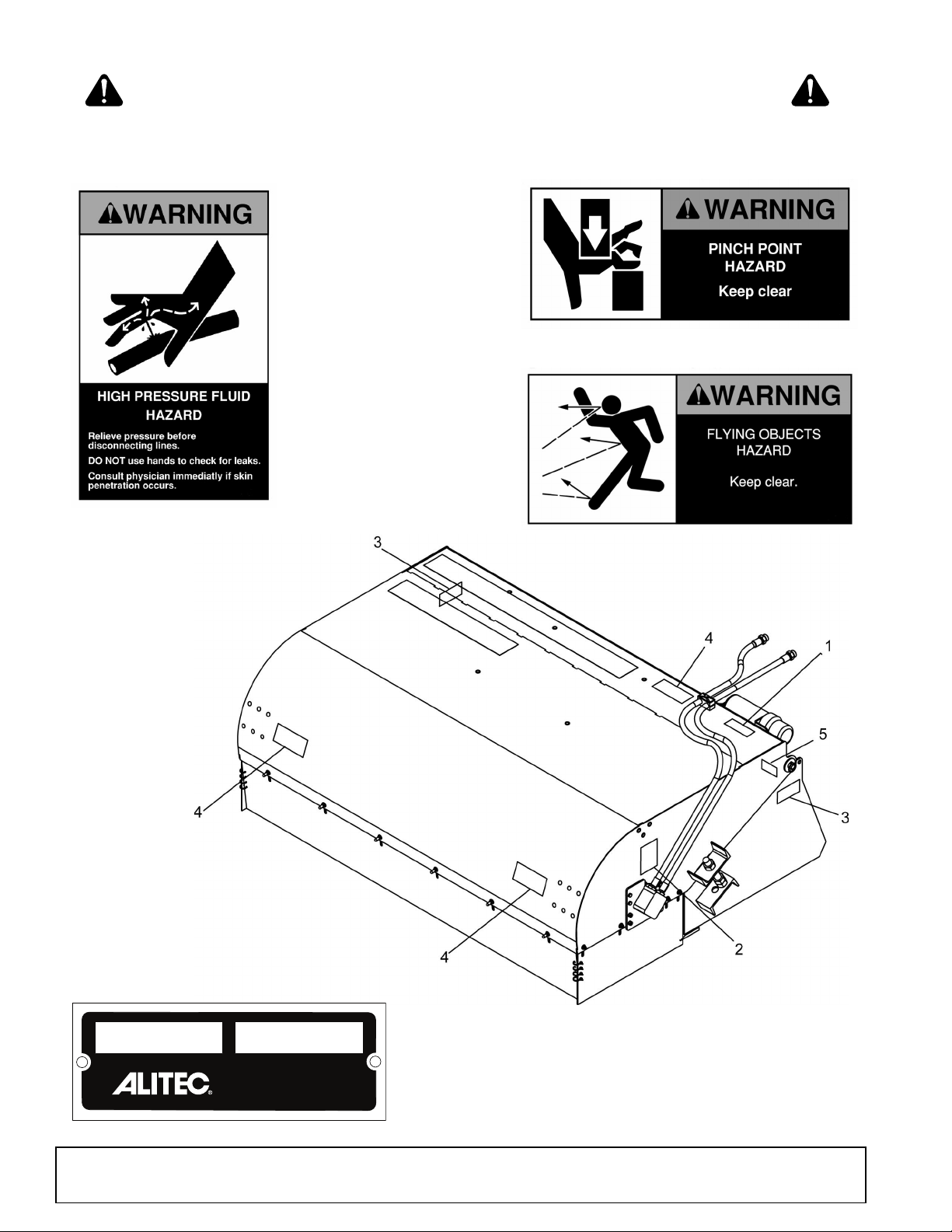
A
3 - PN 1015373
4 - PN 1015362
2 - PN 1015363
5 - SERIAL NUMBER PLATE
SAFETY & INSTRUCTIONAL DECALS
ATTENTION! BECOME ALERT! YOUR SAFETY IS INVOLVED!
Replace Immediately If Damaged!
MODEL NO. SER IAL NO.
8 Safety
Woods Equipment Company
Oregon, Illinois, U.S.A.
MAN0661 (8/10/2007)
Page 9
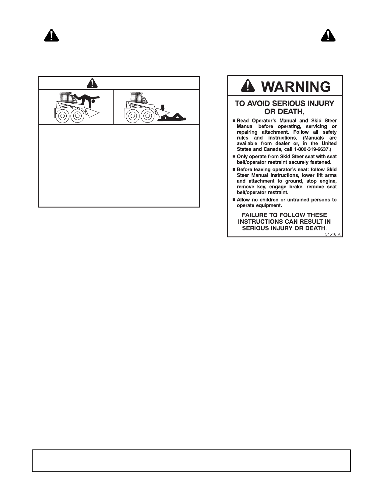
B
1 - PN 54518
WARNING
54519-B
FALLING OFF CAN RESULT IN BEING RUN OVER.
■ Skid steer must have ROPS and seat belt/operator restraint.
Keep seat belt/operator restraint securely fastened.
■ Never allow riders.
RAISED EQUIPMENT CAN DROP AND CRUSH.
■ Never go under raised equipment or raised skid steer lift
arms. They can drop from hydraulic or mechanical failure, or
moving control levers.
■ Service work does not require going under equipment. Read
manual instructions.
FALLING OFF OR GOING UNDER MACHINE CAN RESULT IN
SERIOUS INJURY OR DEATH.
8 - PN 54519
BE CAREFUL!
Use a clean, damp cloth to clean safety decals.
Avoid spraying too close to decals when using a
pressure washer; high-pressure water can enter
through very small scratches or under edges of
decals causing them to peel or come off.
Replacement safety decals can be ordered free
from your Woods dealer. To locate your nearest
dealer, check the Dealer Locator at
www.WoodsEquipment.com, or in the United
States and Canada call 1-800-319-6637.
SAFETY & INSTRUCTIONAL DECALS
ATTENTION! BECOME ALERT! YOUR SAFETY IS INVOLVED!
Replace Immediately If Damaged!
MAN0661 (8/10/2007)
Safety 9
Page 10
OPERATION
WARNING
WARNING
The operator is responsible for the safe operation of
this equipment. Operators must be instructed in and be
capable of the safe operation of the equipment, its
attachments and all controls. Do not allow anyone to
operate this equipment without proper instructions.
The pick-up broom is designed for removing dust, dirt
and fine debris from a flat, level surface. Debris is
swept into the bucket and can then be carried to a suitable location for disposal. Skid steers must be
equipped with an auxiliary hydraulic system capable of
supplying continuous flow for hydraulic motor operation.
Safety instructions are important! Read all
attachment and power unit manuals; follow all
safety rules and safety decal information. (Replacement manuals and safety decals are available from
your dealer. To locate your nearest dealer, check
the Dealer Locator at www.WoodsEquipment.com,
or in the United States and Canada call 1-800-319-
6637.) Failure to follow instructions or safety rules
can result in serious injury or death.
Never allow children or untrained persons to
operate equipment.
Power unit must be equipped with ROPS and
seat belt/operator restraint. Keep seat belt/operator
restraint securely fastened/engaged. Falling off
power unit can result in death from being run over
or crushed. Keep ROPS systems in place at all
times.
Before leaving operator's seat, lower lift arms
and put attachment on the ground. Engage brake,
stop engine, remove key, and remove seat belt.
ATTACH BROOM TO SKID STEER
Read the skid steer operator's manual connecting and
removing instructions.
Position hydraulic hoses so they will not be pinched
when connecting the pick-up broom.
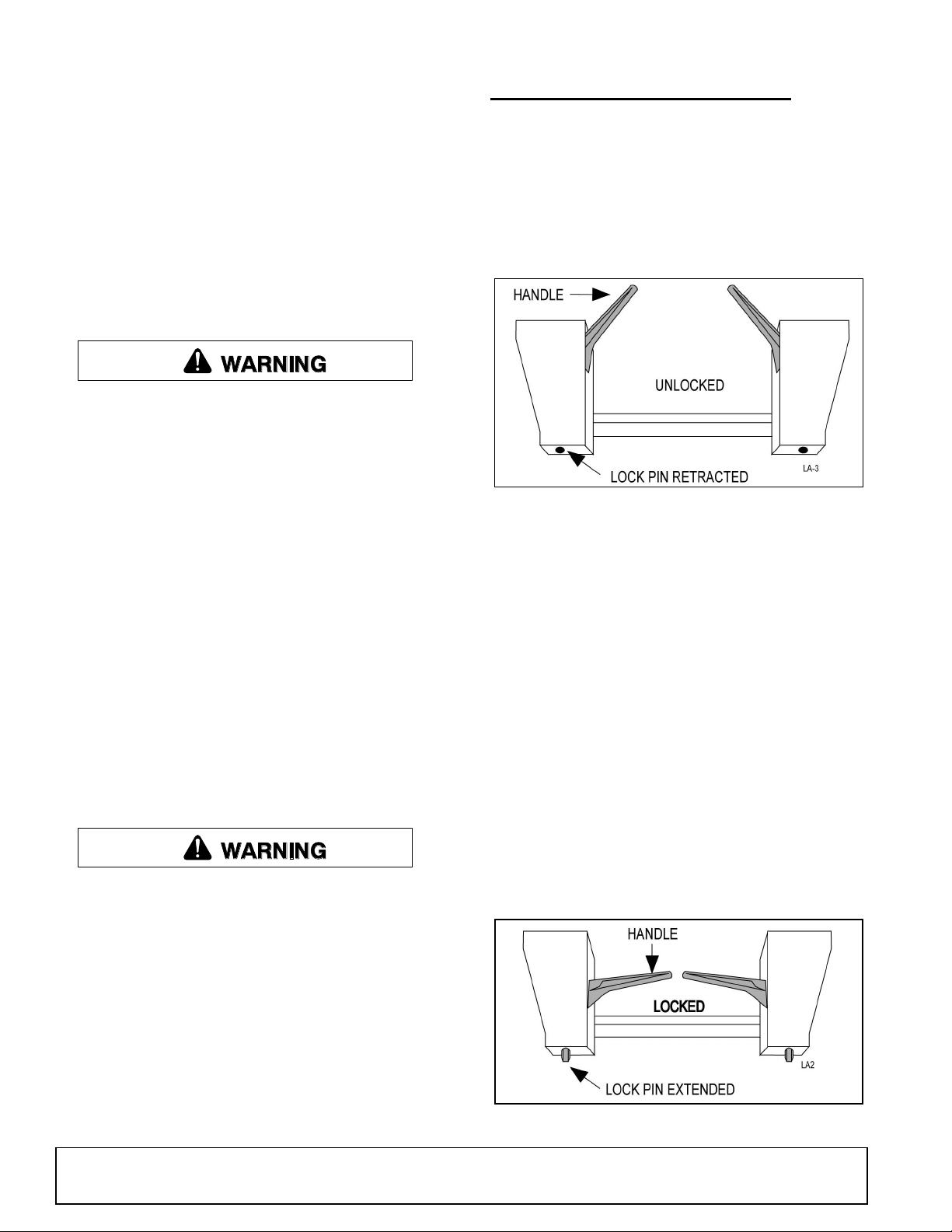
The skid steer coupler handles should be in the
unlocked position and the lock pins retracted.
Figure 1. Skid Steer Coupler Handles - Unlocked
Move to the skid steer operator seat and start engine.
Lower skid steer lift arms to their lowest position.
Carefully move and align the skid steer to the pick-up
broom. The top of the skid steer coupler must slide into
the broom flange, Figure 3.
Roll the skid steer coupler into the pick-up broom so
the coupler handles can be engaged.
Shut off the engine, set brake, and remove key. Dismount the skid steer.
Move the skid steer coupler handles to the locked position, see Figure 2. The lock pins must be completely
extended and secured into the slots provided on the
pick-up broom, Figure 3.
Never go underneath equipment (lowered to the
ground or raised) unless it is properly blocked and
secured. Never place any part of the body underneath equipment or between moveable parts even
when the engine has been turned off. Hydraulic
system leak down, hydraulic system failures,
mechanical failures, or movement of control levers
can cause equipment to drop or rotate unexpectedly and cause severe injury or death. Follow Operator's Manual instructions for working underneath
and blocking requirements or have work done by a
qualified dealer.
10 Operation
Connect hydraulic hoses to skid steer auxiliary quick
couplers.
Figure 2. Skid Steer Coupler Handles - Locked
MAN0661 (8/10/2007)
Page 11
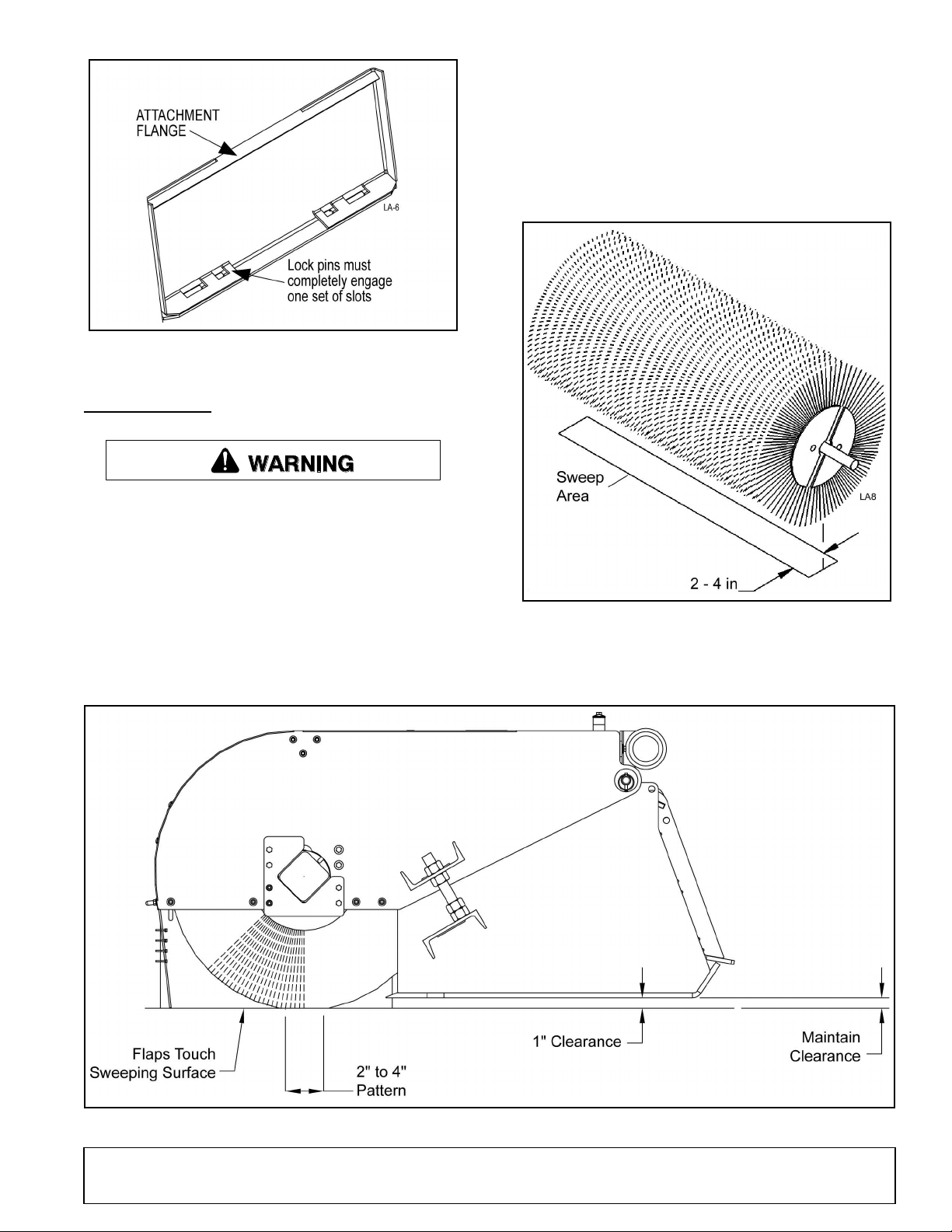
Figure 3. Back of Attachment - Slot Locations
WARNING
ADJUSTMENT
Before leaving operator's seat, lower lift arms
and put attachment on the ground. Engage brake,
stop engine, remove key, and remove seat belt.
Start the broom at a low speed; then, lower it so the
bristle tips touch the ground. Run the broom in a stationary position for ten seconds.
Raise the broom and back away. Switch off the engine
and remove the key. The brush pattern left in the dust
should be two to four inches wide, running the length of
the brush. See Figure 4.
Check Brush Pattern
A properly adjusted brush offers the best sweeping
performance. To check the brush pattern, move the
pick-up broom to a dusty, flat surface. Set the skid
steer parking brake and leave the engine running.
Figure 4. Brush Pattern
If the brush pattern is not two to four inches wide,
adjust brush pattern accordingly.
MAN0661 (8/10/2007)
Figure 5. Adjustment Bolt and Brush Pattern
Operation 11
Page 12
Adjust Brush Height
WARNING
WARNING
1. Loosen the jam nuts above and below the plate on
both sides of the sweeper hood. See Figure 5.
2. Turn adjustment bolt clockwise to make a wider
pattern, or counterclockwise to make a narrower
pattern.
3. Tighten jam nuts and check the new brush pattern.
NOTE: To extend brush life make sure bolts on
both sides are adjusted evenly.
1. Start the skid steer at idle speed and raise the
brush head.
2. Use low engine speeds to save wear and tear on
the sweeper and to prevent dust from billowing up
during sweeping.
NOTE: Do not engage the brush at high engine
speeds. This damages the sweeper and motor.
3. Engage the brush head and lower it to the ground.
4. Increase skid steer engine rpm to sweeping speed.
Travel forward at 5 mph or less.
Adjust Flaps and Plate Shield
Be sure to adjust the metal plate shield and rubber
flaps. The flaps should be all the way down when brush
sections are new. As sections wear, raise the flaps to
avoid dragging on the ground.
OPERATION
When improperly operated, power unit can roll
over or upset. Use of rollover protective structure
(ROPS) with seat belt securely fastened will reduce
the possibility of injury or death if rollover or upset
occurs.
Look down and to the rear and make sure area
is clear before operating in reverse.
Never direct discharge toward people, animals,
or property.
Only engage power when equipment is at
ground operating level. Always disengage power
when equipment is raised off the ground.
NOTICE
■ Shifting brush rotation from forward to reverse
while the brush is rotating damages the sweeper
and motor.
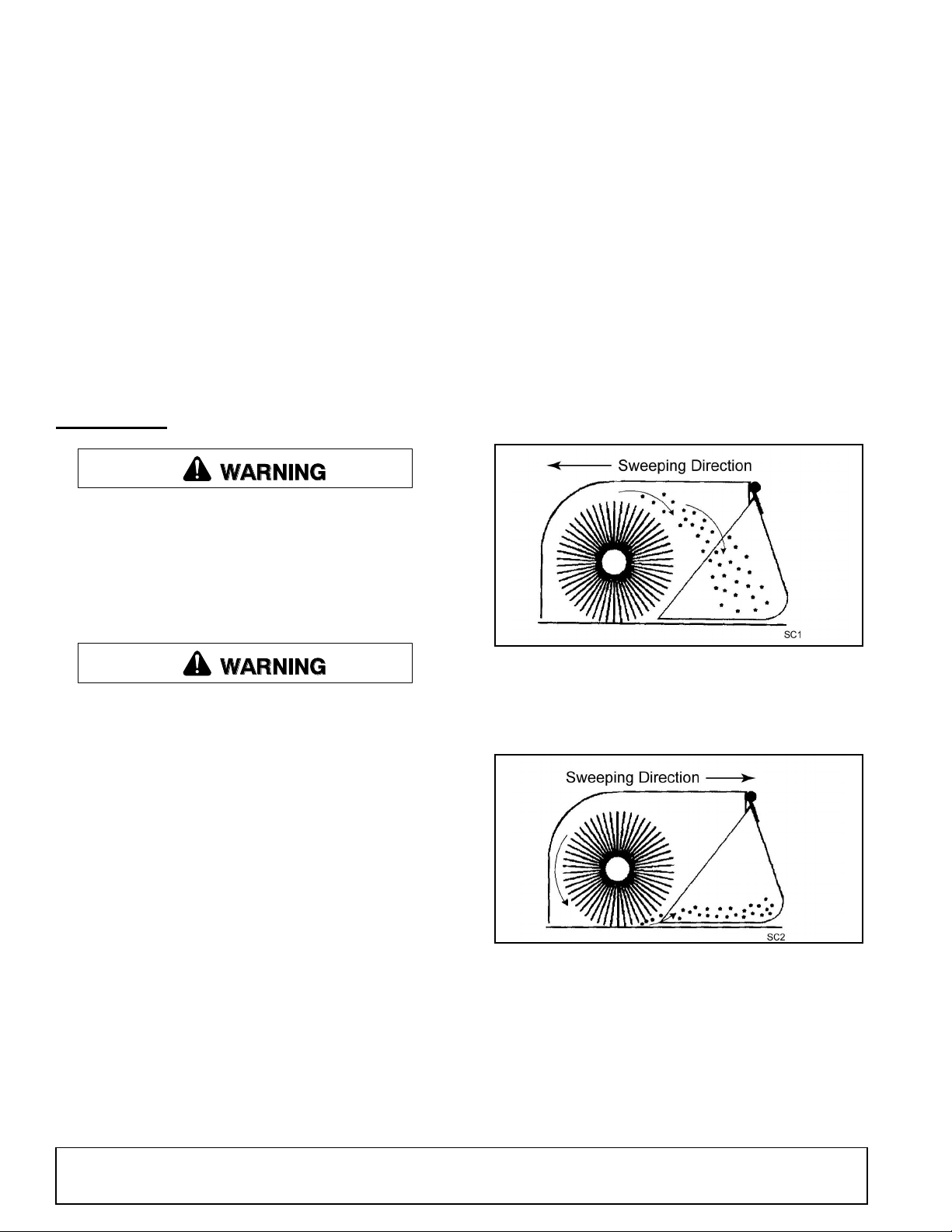
5. When sweeping forward, rotate the brush so debris
goes over the brush and into the bucket (Figure 7).
Figure 6. Forward Sweeping Motion
6. When sweeping in reverse, rotate the brush so
debris is pushed into the bucket, similar to
sweeping into a dustpan (Figure 8).
Read and understand the pick-up broom and skid steer
operator's manuals before operating the pick-up
broom. Failure to do so may result in death, serious
personal injury or property damage.
Never raise the broom more than a few inches off the
ground when traveling from job site to job site.
Carry the broom low to the ground so that the operator
has good visibility and stability. Avoid any sudden
movements.
Sweeping
NOTICE
■ Maximum oil flow is 25 gpm (94.8 liters/min) at
3000 psi (206.8 bars). See the skid steer manual for
oil flow specifications.
12 Operation
Figure 7. Reverse Sweeping Motion
7. If streaking occurs, install plastic ties in flap holes
to hold the front and sides together.
Operating tips
Before Each Use
Perform daily maintenance as indicated in the Maintenance Schedule.
MAN0661 (8/10/2007)
Page 13

Run the sweeper with the skid steer at a slow idle.
WARNING
DANGER
Check for hydraulic leaks or other problems and make
corrections, if necessary, before using the sweeper.
During Use
Dumping Loads
Carry the sweeper low to the ground so that the operator has good visibility and stability. Avoid any sudden
movements. Avoid excessive downward pressure on
the brush sections to prevent excessive wear. A two to
four inch wide pattern for the broom is sufficient for
most applications. Ensure that the adjustment bolts are
equally adjusted in order to prevent an uneven wear
pattern.
Directing Debris
Observe wind direction. Sweeping with the wind makes
sweeping more effective and helps keep debris off the
operator.
Dirt and Gravel
To keep dust at a minimum, plan your sweeping for
days when it is overcast and humid, or after it has
rained. Also, sweep so the wind blows at your back or
in the direction the brush head is angled.
Low brush speeds and moderate ground speeds work
best for cleaning debris from hard surfaces. Brush
speeds that are too fast tend to raise dust because of
the aggressive sweeper action.
AVOID INJURY OR DEATH FROM POWER
LINES:
• Stay away from power lines.
• Electrocution can occur without direct contact.
• Check clearances before raising implement.
• Do not leave the operator's seat if any part of
the tractor or implement contacts electric lines.
Transport to dumping location before raising. Only
dump load while on a firm level surface.
Slowly raise load to required dumping height. Rotate
pick-up broom forward to empty the bucket.
To sweep gravel, use just enough brush speed to roll
gravel, not throw it.
Heavy Debris
For two inches or more of heavy debris, medium/high
and ground speeds of less than five mph are recommended.
Sweep path less than the full width of the broom.
Increase engine speed if debris becomes very heavy.
Transporting
When improperly operated, power unit can roll
over or upset. Use of rollover protective structure
(ROPS) with seat belt securely fastened will reduce
the possibility of injury or death if rollover or upset
occurs.
Always follow safety rules, carry low to ground and
travel slowly.
Only raise a load when dumping.
Figure 8. Dump Position
GUTTER BRUSH (OPTIONAL)
The gutter brush is for sweeping forward only.
When sweeping next to curbs or walls with a gutter
brush, only the bristle tips should touch the vertical surface.
When not using the gutter brush for a short period,
raise it 1-2 inches (25-51mm) off the ground with the
tension chain. During extended periods of non-use,
unhook hydraulic hoses from the gutter brush motor,
remove the gutter brush assembly and connect
hydraulic hoses to run only the main.
MAN0661 (8/10/2007)
Operation 13
Page 14

NOTICE
Shaded area represents the brush touching
the ground on a properly adjusted gutter brush.
■ To prevent contaminates from damaging the
hydraulic system, cap hoses and couplers when
the gutter brush is not in use.
Adjust Gutter Brush Height
When the gutter brush height is properly adjusted, bristles contact the ground as shown in Figure 9.
Figure 10. Gutter Brush and Hood Alignment
To adjust the gutter brush swing:
1. Loosen nuts.
2. Adjust the screw, turning it in for less swing and
turning it out for more swing.
3. Tighten nuts and check adjustment.
Figure 9. Contact Area
To adjust the gutter brush height:
1. Lower the brush to the ground.
2. Loosen the bolts holding the gutter brush motor
mounting plate.
3. Turn the motor mounting plate to the right or left.
4. Adjust the tension chain so it holds the gutter brush
in place.
5. Tighten the bolts holding the motor mounting plate
and check the adjusted brush.
Adjust Gutter Brush Swing
A properly adjusted gutter brush extends the main
brush’s sweeping path, leaving no streaks between the
two paths. For this to happen, the center of the gutter
brush must line up with the outside edge of the
sweeper.
Figure 11. Adjust Gutter Brush Swing
Replace the Gutter Brush
1. Remove four screws to detach the worn gutter
brush for the gutter brush plate.
2. Attach a new gutter brush using the four screws
previously removed.
3. Adjust according to Adjust Gutter Brush Height,
page 14.
14 Operation
MAN0661 (8/10/2007)
Page 15

REMOVE BROOM FROM SKID STEER
WARNING
CAUTION
Do not allow bystanders in the area when oper-
ating, attaching, removing, assembling, or servicing equipment.
Do not disconnect hydraulic lines until all system pressure is relieved. Lower unit to ground,
stop engine, and operate all hydraulic control
levers.
On a hard level surface, lower attachment to the
ground.
Shut off engine, set brake, remove key, remove seat
belt, and release operator restraint before leaving the
skid steer operator's seat.
Disconnect hydraulic hoses from quick couplers. Install
dust plugs and couple hoses together for storage.
Move skid steer coupler handles to the unlocked position, Figure 12. Lock pins must be disengaged from
attachment retaining slots.
NOTICE
■ Do not store polypropylene brushes in direct
sunlight. The material can deteriorate and crumble
before the bristles are worn out.
■ Do not store the broom with weight on the
brushes. Weight will deform them, destroying the
sweeping effectiveness. To avoid this problem,
place broom on blocks.
Inspect the broom thoroughly and prepare for storage.
Repair or replace any damaged components.
Remove the broom as described in Remove Broom
from Skid Steer, page 15. Place on blocks to prevent
brush damage. Clean and cover hose ends, fittings,
and hydraulic ports.
PRE-OPERATION CHECK LIST
(OWNER'S RESPONSIBILITY)
___ Review and follow all safety rules and safety
decal instructions on page 5 through page 9.
___ Check that all safety decals are installed and in
good condition. Replace if damaged.
Figure 12. Skid Steer Coupler Handles - Unlocked
Move to the skid steer operator seat, fasten seat belt,
engage operator restraint, and start engine.
Release brake and roll skid steer coupler until it is disengaged from the attachment. The attachment should
be placed in storage position.
STORAGE
Keep brush away from intense heat or flame.
Brush material can ignite and burn.
Keep children and bystanders away from storage area.
___ Check that all shields and guards are properly
installed and in good condition. Replace if damaged.
___ Check that all hardware and cotter pins are prop-
erly installed and secured.
___ Check that equipment is properly and securely
attached to skid steer.
___ Check all lubrication points and grease as
instructed.
___ Follow procedures in Maintenance, page 16
daily.
___ Do not allow riders.
___ Check and keep all bystanders away from equip-
ment working area.
___ Check that all hydraulic hoses and fittings are in
good condition and not leaking before starting
skid steer. Check that hoses are not twisted, bent
sharply, kinked, frayed or pulled tight. Replace
any damaged hoses immediately.
___ Make sure skid steer ROPS and seat belt are in
good condition. Keep seat belt securely fastened
during operation.
MAN0661 (8/10/2007)
Operation 15
Page 16

OWNER SERVICE
WARNING
WARNING
CAUTION
The information in this section is written for operators
who possess basic mechanical skills. Should you need
help, your dealer has trained service technicians available. For your protection, read and follow all safety
information in this manual.
Regular preventive maintenance and immediate repair
of broken or worn parts will insure maximum efficiency
and long life.
NEVER GO UNDERNEATH EQUIPMENT. Never
place any part of the body underneath equipment
or between moveable parts even when the engine
has been turned off. Hydraulic system leak-down,
hydraulic system failures, mechanical failures, or
movement of control levers can cause equipment
to drop or rotate unexpectedly and cause severe
injury or death.
• Service work does not require going underneath.
• Read Operator's Manual for service instructions or have service performed by a qualified
dealer.
Before leaving operator's seat, lower lift arms
and put attachment on the ground. Engage brake,
stop engine, remove key, and remove seat belt.
Do not allow bystanders in the area when operating, attaching, removing, assembling, or servicing equipment.
Never perform service or maintenance with
engine running.
Make sure shields and guards are properly
installed and in good condition. Replace if damaged.
Keep hands and body away from pressurized
lines. Use paper or cardboard, not hands or other
body parts to check for leaks. Wear safety goggles.
Hydraulic fluid under pressure can easily penetrate
skin and will cause serious injury or death.
must not be twisted, bent sharply, kinked, frayed,
pinched, or come into contact with any moving
parts. Operate moveable components through full
operational range to check clearances. Replace
any damaged hoses immediately.
Do not modify or alter or permit anyone else to
modify or alter the equipment or any of its components in any way.
Make sure all safety decals are installed.
Replace if damaged. (See Safety Decals section for
location.)
Your dealer can supply original equipment
hydraulic accessories and repair parts. Substitute
parts may not meet original equipment specifications and may be dangerous.
Always wear relatively tight and belted clothing
to avoid getting caught in moving parts. Wear
sturdy, rough-soled work shoes and protective
equipment for eyes, hair, hands, hearing, and head;
and respirator or filter mask where appropriate.
Maintenance
Inspect for leaks and correct as necessary.
Run engine at a slow idle, checking for leaks.
Operate broom to ensure it is working properly.
Check the fluid level in skid steer reservoir and add
fluid as required.
Procedure Daily
50
Hours
Make sure that all operating and service personnel know that if hydraulic fluid penetrates skin, it
must be surgically removed as soon as possible by
a doctor familiar with this form of injury or gangrene, serious injury, or death will result. CONTACT A PHYSICIAN IMMEDIATELY IF FLUID
ENTERS SKIN OR EYES. DO NOT DELAY.
Make sure all hydraulic hoses, fittings, and
valves are in good condition and not leaking before
starting power unit or using equipment. Check and
route hoses carefully to prevent damage. Hoses
16 Owner Service
Level brush
Check brush pattern
Clean air filter, skid steer
Hydraulic fittings and hoses, tighten
Grease fittings
Check hydraulic fluid level
Tighten hardware
MAN0661 (8/10/2007)
✔
✔
✔
✔
✔
✔
✔
Page 17

CLEANING
After Each Use
● Remove large debris such as clumps of dirt, grass,
crop residue, etc. from machine.
● Inspect machine and replace worn or damaged
parts.
● Replace any safety decals that are missing or not
readable.
Periodically or Before Extended Storage
● Clean large debris such as clumps of dirt, grass,
crop residue, etc. from machine.
● Remove the remainder using a low-pressure water
spray.
1. Be careful when spraying near scratched or torn
safety decals or near edges of decals as water
spray can peel decal off surface.
2. Be careful when spraying near chipped or
scratched paint as water spray can lift paint.
3. If a pressure washer is used, follow the advice
of the pressure washer manufacturer.
● Inspect machine and replace worn or damaged
parts.
● Sand down scratches and the edges of areas of
missing paint and coat with Woods spray paint of
matching color (purchase from your Woods
dealer).
● Replace any safety decals that are missing or not
readable (supplied free by your Woods dealer).
See Safety Decals section for location drawing.
MAN0661 (8/10/2007)
Owner Service 17
Page 18

TROUBLESHOOTING
PROBLEM POSSIBLE CAUSE SOLUTION
Motor for broom will not operate. Auxiliary hydraulics control on prime
mover is activated in the wrong
position.
Hoses improperly connected to prime
mover.
Hoses on prime mover are
obstructed.
Hoses on broom are obstructed. Clear obstruction on broom.
The motor has failed. Replace the motor.
Sluggish broom operation. Insufficient oil flow from the prime
mover.
One or more seals have failed in the
motor.
Hydraulic filter on prime mover is
dirty.
Motor runs but broom does not. Motor shaft has a sheared key. Replace key.
Oil leaks from motor. One or more seals have failed in the
motor.
Verify controls: See prime mover
owner’s manual.
Connect hoses correctly to prime
mover.
Clear obstruction on prime mover.
Increase engine RPM.
Replace the seals or motor.
Replace filter.
Replace the seals or motor.
Seals on the fittings are damaged. Replace seals or fittings.
Fittings are loose or damaged. Tighten or replace fittings.
Hydraulic hoses are loose or
damaged.
Brush rotates in wrong direction. Hoses installed incorrectly. Switch hose connections.
Brush slows or stops when sweeping. Brush pattern too wide. Adjust brush pattern.
Travel speed too fast. Reduce travel speed.
Trying to sweep too much material at
once.
Hydraulic motor is failing. Replace Motor.
Brush wears very quickly. Brush pattern too wide. Adjust brush pattern.
Tighten or replace hoses.
Reduce amount of material being
swept; make more passes.
18 Troubleshooting
MAN0661 (8/10/2007)
Page 19

TROUBLESHOOTING
PROBLEM POSSIBLE CAUSE SOLUTION
Excessive hydraulic oil temperature. Low hydraulic oil level on the prime
mover.
Hydraulic hoses are obstructed. Clear obstructions in hoses.
Hydraulic oil and/or filter on prime
mover are dirty.
Quick couplers are not properly
seated.
Brush pattern too wide. Adjust brush pattern. See “Check
Travel speed too fast. Reduce travel speed.
Trying to sweep too much material at
once.
Hydraulic motor is failing. Replace motor.
Hydraulic quick coupler leaks. Quick coupler poppet is unseated or
damaged.
Add hydraulic fluid.
Replace hydraulic oil and/or filter on
prime mover.
Reconnect quick couplers properly.
Brush Pattern” on page 11..
Reduce the amount of material being
swept. Make more passes.
Reconnect or replace the quick
couplers.
MAN0661 (8/10/2007)
Troubleshooting 19
Page 20

DEALER SERVICE
WARNING
CAUTION
The information in this section is written for dealer service personnel. The repair described here requires
special skills and tools. If your shop is not properly
equipped or your mechanics are not properly trained in
this type of repair, you may be time and money ahead
to replace complete assemblies.
NEVER GO UNDERNEATH EQUIPMENT. Never
place any part of the body underneath equipment
or between moveable parts even when the engine
has been turned off. Hydraulic system leak-down,
hydraulic system failures, mechanical failures, or
movement of control levers can cause equipment
to drop or rotate unexpectedly and cause severe
injury or death.
• Service work does not require going underneath.
• Read Operator's Manual for service instructions or have service performed by a qualified
dealer.
Do not allow bystanders in the area when operating, attaching, removing, assembling, or servicing equipment.
Do not modify or alter or permit anyone else to
modify or alter the equipment or any of its components in any way.
Do not disconnect hydraulic lines until machine
is securely blocked or placed in lowest position
and system pressure is released by operating
valve levers.
Make sure attachment is properly secured,
adjusted, and in good operating condition.
Make sure all safety decals are installed.
Replace if damaged. (See Safety Decals section for
location.)
Make sure shields and guards are properly
installed and in good condition. Replace if damaged.
sturdy, rough-soled work shoes and protective
equipment for eyes, hair, hands, hearing, and head;
and respirator or filter mask where appropriate.
REPLACE BRUSH SECTIONS
1. Remove motor mount screws. Retain hardware for
reinstallation. Remove motor mount.
2. Remove bearing mounting plate screws from side.
Retain hardware for reinstallation.
3. Remove the side flaps. Retain hardware for
reinstallation.
4. Lift sweeper body leaving core on ground.
5. Remove the bearing mounting plate and section
retainer plate. Retain hardware for reinstallation.
6. Remove old sections.
Install New Sections
1. Number the tubes on the core as 1, 2 and 3. See
Figure 13.
Always wear relatively tight and belted clothing
to avoid getting caught in moving parts. Wear
20 Dealer Service
Figure 13. Number Tubes
2. Slide the first section onto the core with the drive
pins on either side of tube 1. Make sure that the
drive pins angle upward (Figure 13).
MAN0661 (8/10/2007)
Page 21

3. Place the second section on the core with the drive
pins on either side of tube 2. Make sure drive pins
angle downward (Figure 14).
Figure 14. Second Section
4. Put the third section on with the drive pins around
tube 3. Make sure drive pins angle upward.
5. Slide sections on until the core is full. Make sure to
alternate the tubes used and the direction of the
drive pins.
Assemble Unit
1. Attach the section retainer and bearing mounting
plate with previously removed hardware.
2. Lay core on ground. Lower body over core.
3. Attach bearing mounting plate with previously
removed hardware.
4. Reattach motor mount with previously removed
hardware.
NOTES
MAN0661 (8/10/2007)
Dealer Service 21
Page 22

DEALER CHECK LISTS
PRE-DELIVERY CHECK LIST
(DEALER’S RESPONSIBILITY)
Inspect the equipment thoroughly after assembly to
ensure it is set up properly before delivering it to the
customer.
The following check lists are a reminder of points to
inspect. Check off each item as it is found satisfactory
or after proper adjustment is made.
___ Check that all safety decals are installed and in
good condition. Replace if damaged.
___ Check that shields and guards are properly
installed and in good condition. Replace if damaged.
___ Check lock bars on attachment carrier to make
sure they are in place.
___ Check all bolts to be sure they are tight.
___ Check that all cotter pins and safety pins are
properly installed. Replace if damaged.
___ Check and grease all lubrication points.
DELIVERY CHECK LIST
(DEALER’S RESPONSIBILITY
___ Show customer how to make adjustments.
___ Instruct customer how to lubricate and explain
importance of lubrication.
___ Point out the safety decals. Explain their meaning
and the need to keep them in place and in good
condition. Emphasize the increased safety hazards when instructions are not followed.
___ Present Operator's Manual and request that cus-
tomer and all operators read it before operating
equipment. Point out the manual safety rules,
explain their meanings and emphasize the
increased safety hazards that exist when safety
rules are not followed.
___ Explain to customer the potential crushing haz-
ards of going underneath raised equipment.
Instruct customer that service work does not
require going underneath unit and never to do so.
___ Show customer the safe, proper procedures to be
used when mounting, dismounting, and storing
equipment.
___ Explain to customer that when equipment is
transported on a road or highway, safety devices
should be used to give adequate warning to operators of other vehicles.
___ Make customer aware of optional equipment
available so that customer can make proper
choices as required.
___ Point out all guards and shields. Explain their
importance and the safety hazards that exist
when not kept in place and in good condition.
22 Dealer Check Lists
MAN0661 (8/10/2007)
Page 23

ASSEMBLY INSTRUCTIONS
WARNING
CAUTION
DEALER SET-UP INSTRUCTIONS
Assembly of this pick-up broom is the responsibility of
the WOODS dealer. It should be delivered to the owner
completely assembled, lubricated and adjusted for
normal conditions.
Keep hands and body away from pressurized
lines. Use paper or cardboard, not hands or other
body parts to check for leaks. Wear safety goggles.
Hydraulic fluid under pressure can easily penetrate
skin and will cause serious injury or death.
Make sure that all operating and service personnel know that if hydraulic fluid penetrates skin, it
must be surgically removed as soon as possible by
a doctor familiar with this form of injury or gangrene, serious injury, or death will result. CONTACT A PHYSICIAN IMMEDIATELY IF FLUID
ENTERS SKIN OR EYES. DO NOT DELAY.
Route hydraulic hoses carefully to prevent damage. Hoses must not be twisted, bent sharply,
kinked, frayed, pinched, or come into contact with
any moving parts. Operate moveable components
through full operational range to check clearances.
Replace any damaged hose immediately.
Do not allow bystanders in the area when operating, attaching, removing, assembling, or servicing equipment.
Do not modify or alter or permit anyone else to
modify or alter the equipment or any of its components in any way.
Always wear relatively tight and belted clothing
to avoid getting caught in moving parts. Wear
sturdy, rough-soled work shoes and protective
equipment for eyes, hair, hands, hearing, and head;
and respirator or filter mask where appropriate.
When using a gutter brush, only the main brush
sweeps in the over-the-brush direction.
1. Remove plugs from holes in either the right or left
side of the unit (depending on which side the gutter
brush is to be installed).
2. Attach gutter brush mounting plate (15) and
attachment plate (4) to broom hood using six cap
screws (13), lock washers (25), and flat washers
(22).
3. Insert pivot pin (40) into pivot assembly (5), place
pivot arm (3) over pivot assembly and align holes.
Secure assembly together using clevis pin (24) and
cotter pin (30).
4. Insert bushings (6) into each end of attachment
plate (4).
5. Slide pivot assembly into attachment plate and
secure using bushing (24) and roll pin (31).
6. Attach motor (14) to motor mount plate (7) using
four cap screws (18) and lock washers (26).
7. Attach brush head (1) to brush mounting plate (2)
using four cap screws (17), flat washers (22), and
lock nuts (27).
8. Attach motor mount plate to pivot arm using two
carriage bolts (20), flat washers (23), lock washers
(26), and hex nuts (28).
9. Attach brush assembly to motor using cap screw
(16), lock washer (25), and flat washer (22).
10. Attach swing stop bolt (19) and two hex nuts (29) to
the pivot arm.
11. Remove plugs from holes on the top side of the
broom hood. Attach chain plate (11) to hood using
three cap screws (16), lock washers (25), and flat
washers (23).
12. Attach chain (35) and quick link (36) to top of pivot
assembly and opposite end of chain to chain plate
on the side of the broom hood.
INSTALL GUTTER BRUSH (OPTIONAL)
Pick-up brooms are designed to carry only one gutter
brush. Never install more than one gutter brush.
MAN0661 (8/10/2007)
Install Hydraulic Hoses
Use Figure 16 or Figure 17 to install hydraulic hoses for
either right or left gutter brush application.
Complete Dealer Check List on page 22 before
delivering broom to the customer.
Assembly 23
Page 24

1. Brush
2. Brush mounting plate
3. Pivot arm
4. Attachment plate
5. Pivot assembly
6. Pivot bushing
7. Motor mount plate
8. Hose, 1/2 x 87 (see below)
10. Hose, 1/2 x 140 (see below)
11. Chain attachment plate
12. Hydraulic adapter (see below)
13. 5/16 NC x 1-1/4 HHCS
14. Hydraulic motor
15. Mounting plate
16. 5/16 NC x 1 HHCS
17. 5/16 NC x 2 HHCS
18. 3/8 NC x 1 HHCS
19. 1/2 NC x 2-1/2 HHCS
20. 3/8 NC x 1-1/4 Carriage bolt
21. Plastic tie (see below)
22. 5/16 Flat washer
23. 3/8 Flat washer
24. Bushing 10 ga x 1-1/2 x 2-1/4
25. 5/16 Lock washer
26. 3/8 Lock washer
27. 5/16 NC Lock nut
28. 3/8 NC Hex nut
29. 1/2 NC Hex nut
30. 1/8 x 2 Cotter pin
31. 1/4 x 2 Roll pin
34. 3/4 x 3-1/2 Clevis pin
35. Chain (26 links)
36. Quick link
37. 5/16 NC x 2-1/2 HHCS
(see below)
38. Hose clamp (see below)
39. Clamp cradle (see below)
40. Pivot pin
Figure 16. Right Gutter Brush Installation Figure 17. Left Gutter Brush Installation
24 Assembly
Figure 15. Gutter Brush Assembly
MAN0661 (8/10/2007)
Page 25

PB600-2 & PB720-2 PICK-UP BROOM ASSEMBLY
CORE ASSEMBLY . . . . . . . . . . . . . . . . . . . . . . . . . . . .PAGE 26
MOTOR ASSEMBLY . . . . . . . . . . . . . . . . . . . . . . . . . .PAGE 27
HOOD ASSEMBLY . . . . . . . . . . . . . . . . . . . . . . . . . . . .PAGE 28
HOPPER ASSEMBLY. . . . . . . . . . . . . . . . . . . . . . . . . .PAGE 29
MAN0661 (8/10/2007)
Parts 25
Page 26

CORE ASSEMBLY
REF PART QTY DESCRIPTION
1 14562 * 7 HHCS 5/16 NC x 1 GR5
2 2472 * 9 Washer 5/16 lock
3 4378 * 4 Washer 5/16 std flat
4 4529 * 2 Hex nut 5/16 NC
5 24409 * 2 Carriage bolt 5/16 NC x 1
6 1015995 2 Flange bearing 2 hole
7 54691 1 Bearing, 1 RD w/collar
8 1027510 1 Core PB600-2 -or-
8 1027511 1 Core PB720-2
9 1015374 1 Plate core retainer PB
10 1015366 1 Plate mtg bearing PB
11 1015393 3 Clip nut U-style 5/16-18
12 1015370 4 .313 Rivet nut .150 - .312
13 1015395 1 Brush set, mixed PB600-2 (NS)
14 1015360 1 Brush set, mixed PB720-2 (NS)
15 54627 1 Brush set, poly PB600-2 (NS)
16 1015361 1 Brush set, poly PB720-2 (NS)
* Standard hardware, obtain locally
NS Not shown
REF PART QTY DESCRIPTION
26 Parts
MAN0661 (8/10/2007)
Page 27

MOTOR ASSEMBLY
REF PART QTY DESCRIPTION
1 1015394 2 Hose 1/2 x 120 10 MORS-12MOR
2 54644 1 Motor, Hyd 24.9CI, 25GPM
2a 54740 1 Seal kit
3 54601 * 1 Clip, hairpin 14GA x 1-3/4
4 14562 * 4 HHCS 5/16 NC x 1 GR5
5 10509 * 1 HHCS 5/16 NC x 2-1/2 GR5
6 54682 4 HHCS 5/16 NC x 1-1/4 GR8
7 2472 * 2 Washer 5/16 lock
8 4378 * 10 Washer 5/16 std flat
9 4529 * 2 Nut, hex 5/16 NC
10 1027512 1 Plate, mounting, motor, hydraulic
11 1027513 1 Plate, mounting, motor, inner
12 1015375 1 Cover plate F/.88 OD
13 1015372 1 Hose cradle F/.88 OD
14 1015370 6 .313 Rivet nut .150 - .312
* Standard hardware, obtain locally
REF PART QTY DESCRIPTION
MAN0661 (8/10/2007)
Parts 27
Page 28

HOOD ASSEMBLY
REF PART QTY DESCRIPTION
1 54613 * 2 Pin, link #1600
2 14562 * 2 HHCS 5/16 NC x 1 GR5
3 21417 * 8 Cable tie .30 x 14.5 nylon
4 54684 1 Pad, non-slip, 4 x 24, blk
5 2472 * 2 Washer 5/16 lock
6 4378 * 2 Washer 5/16 std flat
7 73212 * 8 Carriage bolt 1/4 NC x 1 GR5
8 5645 * 5 Carriage bolt 1/4 NC x 1-1/4
9 5336 * 13 Washer 1/4 flat ZP
10 54674 8 Nut, hex, GR2 1-8
11 1985 * 13 Washer 1/4 std lock
12 5288 * 13 Nut hex 1/4 NC
13 28539 2 Washer 7/8 std SAE flat
14 1003828 1 Manual tube
15 1027507 1 Hood, PB600-2 -or-
15 1027508 1 Hood, PB720-2
16 1027509 2 Rod, threaded 1-8 x 7
17 1015379 1 Plate support flap long PB
18 1015367 1 Non-skid tape 4-42
19 1015376 2 Flap side PB
20 1015383 2 Plate support flat side small
21 1015387 2 Plate support flap side large
22 1015377 1 Flap front PB600-2
22 1015354 1 Flap front PB720-2
23 1015388 1 Rod hinge PB600-2
23 1015357 1 Rod hinge PB720-2
24 1015380 1 Plate support flap short PB
25 1015389 12 Plug black 3/8
26 1015382 5 Vinyl cap .25 - .50
27 1015370 12 .313 Rivet nut .150 - .312
28 1015369 2 .313 Rivet nut .027 - .015
* Standard hardware, obtain locally
REF PART QTY DESCRIPTION
28 Parts
MAN0661 (8/10/2007)
Page 29

HOPPER ASSEMBLY
REF PART QTY DESCRIPTION
1 855 * - Lock washer 1/2
2 1093 * - Hex nut 1/2 NC plated
3 7152 - Plow bolt 1/2 NC x 1-1/2
4 1027502 1 Cutting edge, PB600-2
4 1027503 1 Cutting edge, PB720-2
5 1027504 1 Bucket, PB600-2
5 1027505 1 Bucket, PB720-2
6 1027506 2 Spacer, pipe, PB720-2
* Standard hardware, obtain locally
MAN0661 (8/10/2007)
Parts 29
Page 30

GUTTER BRUSH ASSEMBLY (OPTIONAL)
30 Parts
MAN0661 (8/10/2007)
Page 31

GUTTER BRUSH ASSEMBLY PARTS LIST (OPTIONAL)
REF PART QTY DESCRIPTION
1 54626 1 Brush, poly
2 54696 1 Plate, brush mounting
3 54697 1 Arm
4 1016010 1 Plate, attachment
5 1016013 1 Pivot, weldment
6 54694 2 Bushing, pivot
7 54698 1 Plate, motor mount
8 1016014 1 Hose, 1/2 x 87
10 1016015 1 Hose, 1/2 x 140
11 1016011 1 Plate, adjustment
12 1016004 4 Adapter, hydraulic
13 54682 6 HHCS, 5/16 NC x 1-1/4 GR8
14 54642 1 Motor, hydraulic
14A 1019645 1 Seal kit, motor
15 1016009 1 Plate, mounting
16 14562 * 4 HHCS, 5/16 NC x 1 GR5
17 54680 * 4 HHCS, 5/16 NC x 2 GR5
18 839 * 4 HHCS, 3/8 NC x 1 GR5
19 62789 * 1 HHCS, 1/2 NC x 2 GR5
20 24890 * 2 Bolt, carriage 3/8 NC x 1-1/4 GR5
REF PART QTY DESCRIPTION
21 21417 * 4 Ties, nylon cable, .30 x 14.5"
22 1016006 * 14 Washer, flat 5/16
23 565 * 2 Washer, flat 3/8
24 54699 1 Bushing, 10 ga, 1-1/2 - 2-1/4
25 2472 * 10 Washer, lock 5/16
26 838 * 6 Washer, lock 3/8
27 14139 * 4 Nut, flange lock 5/16 NC
28 835 * 2 Nut, hex 3/8 NC
29 1093 * 2 Nut, hex 1/2 NC
30 M0021 * 1 Pin, cotter 1/8 x 2
31 54657 1 Pin, roll 1/4 x 2
32 1016008 1 Grease fitting, 1/4-28 self-tapping
33 1015370 6 Nut, rivet 5/16-18 x .15 x .312 Grip
34 1016001 1 Pin, clevis 3/4 x 3-1/2
35 1016007 1 Chain, 3/16 (26 Links)
36 1016005 1 Link, quick 3/16
40 1016012 1 Pin, gutter brush pivot
* Standard hardware, obtain locally
HHCS = Hex head cap screw
MAN0661 (8/10/2007)
Parts 31
Page 32

QUICK COUPLER KITS
High-Flow with Auxiliary High-Flow with No Auxiliary Low-Flow
Make QC Kit Description QC Kit Description QC Kit Description
Bobcat HC356 Flush Face HC355 Flush Face HC357 Flush Face
HC243 Poppet
Vintage
Case 1013825 Flush Face HC212 Flush Face HC279 Flush Face
HC278 Flush Face HC211 Ag Ball Valve
HC209 Flush Face &
Vintage
Cat HC538 Flush Face 1014196 Flush Face 1014197 Flush Face
Daewoo HC209 Flush Face HC212 Flush Face HC211 Ag Ball Valve
Gehl HC398 Flush Face 1014195 Flush Face HC400 Flush Face
Vintage
John Deere 1014198 Flush Face 1013826 Flush Face HC310 Flush Face
Komatsu 1013834 Flush Face 1013833 Flush Face 1013835 Flush Face
New Holland 1014199 Flush Face HC308 Flush Face HC310 Flush Face
Scat Trak HC537 Flush Face HC243 Poppet
Ag Ball Valve
HC305 Poppet &
Ag Ball
HC211 Ag Ball Valve
QUICK COUPLER KIT COMPONENTS
QC KIT Includes Style Male/Female Body
Size
HC209 HC193 Flush Face Male 3/4 SAE #12 O-ring
HC194 Flush Face Female 3/4 SAE #12 O-ring
HC195 Ag Ball Female 1/2 1/2-14 NPT
HC196 Ag Ball Male 1/2 1/2-14 NPT
HC197 Flush Face Female 1/2 SAE #10 O-ring
HC211 HC195 Ag Ball Female 1/2 1/2-14 NPT
HC196 Ag Ball Male 1/2 1/2-14 NPT
HC212 HC193 Flush Face Male 3/4 SAE #12 O-ring
HC194 Flush Face Female 3/4 SAE #12 O-ring
HC197 Flush Face Female 1/2 SAE #10 O-ring
HC278 HC193 Flush Face Male 3/4 SAE #12 O-ring
HC194 Flush Face Female 3/4 SAE #12 O-ring
HC197 Flush Face Female 1/2 SAE #10 O-ring
HC201 Flush Face Male 1/2 SAE #10 O-ring
HC279 HC197 Flush Face Female 1/2 SAE #10 O-ring
HC201 Flush Face Male 1/2 SAE #10 O-ring
Hose End
32 Quick Coupler
Quick Coupler Chart (Rev. 10/20/2006)
Page 33

QUICK COUPLER KIT COMPONENTS
QC KIT Includes Style Male/Female Body
Size
HC308 HC416 Flush Face Female 5/8 SAE #12 O-ring
HC417 Flush Face Male 5/8 SAE #12 O-ring
HC418 Flush Face Male 3/8 SAE #8 O-ring
HC310 HC414 Flush Face Male 1/2 SAE #12 O-ring
HC415 Flush Face Female 1/2 SAE #12 O-ring
HC355 HC344 Flush Face Male 12 mm SAE #12 O-ring
HC345 Flush Face Female 12 mm SAE #12 O-ring
HC346 Flush Face Female 9 mm SAE #8 O-ring
HC356 HC342 Flush Face Female 7 mm SAE #6 O-ring
HC343 Flush Face Male 7 mm SAE #6 O-ring
HC344 Flush Face Male 12 mm SAE #12 O-ring
HC345 Flush Face Female 12 mm SAE #12 O-ring
HC346 Flush Face Female 9 mm SAE #8 O-ring
HC357 HC344 Flush Face Male 12 mm SAE #12 O-ring
HC345 Flush Face Female 12 mm SAE #12 O-ring
HC398 HC344 Flush Face Male 12 mm SAE #12 O-ring
HC345 Flush Face Female 12 mm SAE #12 O-ring
HC346 Flush Face Female 9 mm SAE #8 O-ring
HC400 HC344 Flush Face Male 12 mm SAE #12 O-ring
HC345 Flush Face Female 12 mm SAE #12 O-ring
HC537 HC415 Flush Face Female 1/2 SAE #12 O-ring
HC416 Flush Face Female 5/8 SAE #12 O-ring
HC417 Flush Face Male 5/8 SAE #12 O-ring
HC418 Flush Face Male 3/8 SAE #8 O-ring
HC538 HC521 Flush Face Female 16 mm SAE #12 O-ring
HC522 Flush Face Male 16 mm SAE #12 O-ring
1532994 Flush Face Female 3/4 SAE #12 O-ring
1532995 Flush Face Male 3/4 SAE #12 O-ring
1532997 Flush Face Female 1/2 SAE #8 O-ring
1013825 HC417 Flush Face Male 5/8 SAE #12 O-ring
HC418 Flush Face Male 3/8 SAE #8 O-ring
HC545 Flush Face Female 5/8 SAE #12 O-ring
HC546 Flush Face Female 1/2 SAE #10 O-ring
HC547 Flush Face Male 1/2 SAE #10 O-ring
1013826 HC343 Flush Face Male 7 mm SAE #6 O-ring
HC521 Flush Face Female 16 mm SAE #12 O-ring
HC522 Flush Face Male 16 mm SAE #12 O-ring
1013833 HC415 Flush Face Female 1/2 SAE #12 O-ring
HC521 Flush Face Female 16 mm SAE #12 O-ring
HC522 Flush Face Male 16 mm SAE #12 O-ring
Hose End
Quick Coupler Chart (Rev. 10/20/2006)
Quick Coupler 33
Page 34

QUICK COUPLER KIT COMPONENTS
QC KIT Includes Style Male/Female Body
Size
1013834 HC414 Flush Face Male 1/2 SAE #12 O-ring
HC415 Flush Face Female 1/2 SAE #12 O-ring
HC521 Flush Face Female 16 mm SAE #12 O-ring
HC522 Flush Face Male 16 mm SAE #12 O-ring
1013835 46058 Flush Face M/F Set 3/4 SAE #12 O-ring
1014195 HC344 Flush Face Male 12 mm SAE #12 O-ring
HC345 Flush Face Female 12 mm SAE #12 O-ring
HC346 Flush Face Female 9 mm SAE #8 O-ring
1014196 HC521 Flush Face Female 16 mm SAE #12 O-ring
HC522 Flush Face Male 16 mm SAE #12 O-ring
1532997 Flush Face Female 1/2 SAE #8 O-ring
1014197 1532994 Flush Face Female 3/4 SAE #10 O-ring
1532995 Flush Face Male 3/4 SAE #10 O-ring
1014198 HC343 Flush Face Male 7 mm SAE #6 O-ring
HC414 Flush Face Male 1/2 SAE #12 O-ring
HC415 Flush Face Female 1/2 SAE #12 O-ring
HC521 Flush Face Female 16 mm SAE #12 O-ring
HC522 Flush Face Male 16 mm SAE #12 O-ring
1014199 HC414 Flush Face Male 1/2 SAE #12 O-ring
HC415 Flush Face Female 1/2 SAE #12 O-ring
HC416 Flush Face Female 5/8 SAE #12 O-ring
HC417 Flush Face Male 5/8 SAE #12 O-ring
HC418 Flush Face Male 3/8 SAE #8 O-ring
Hose End
34 Quick Coupler
Quick Coupler Chart (Rev. 10/20/2006)
Page 35

FITTING TORQUE CHART
Always tighten fittings to these values unless a different torque value is listed
for a specific service procedure.
Make sure fastener threads are clean and threads are engaged properly.
All torque values are adopted from SAE J514 and SAE J1453.
SAE
Dash
Size
SAE (JIC)
37° Flare Thread
Size
2 5/16 - 24 5/16 - 24 ---
3 3/8 - 24 3/8 - 24 ---
4 7/16 - 20 7/16 - 20 9/16 - 18
5 1/2 - 20 1/2 - 20 ---
6 9/16 - 18 9/16 - 18 11/16 - 16
8 3/4 - 16 3/4 - 16 13/16 - 16
10 7/8 - 14 7/8 - 14 1 - 14
12 1-1/16 - 12 1-1/16 - 12 1-3/16 - 12
14 1-3/16 - 12 1-3/16 - 12 ---
16 1-5/16 - 12 1-5/16 - 12 1-7/16 - 12
20 1-5/8 - 12 1-5/8 - 12 1-11/16 - 12
24 1-7/8 - 12 1-7/8 - 12 2 - 12
32 2-1/2 - 12 2-1/2 - 12 ---
Size
O-Ring Style
Straight Thread
Size
Seal-Lok
Thread
TORQUE
SAE 37° Flare O-Ring Straight Thread Seal-Lok
Lbs-Ft N-m Lbs-Ft N-m Lbs-Ft N-m
2 4545------
3 811912------
4 12 16 16 22 18 25
5 15 20 22 30 --- ---
6 18 25 35 48 27 37
8 37 50 60 82 40 54
10 48 65 105 143 63 86
12 74 100 140 190 92 125
14 88 120 184 250 --- ---
16 100 135 221 300 122 165
20 133 180 258 350 147 200
24 166 225 317 430 166 225
32 236 320 --- --- --- ---
Fitting Torque Chart (7/15/2005)
Appendix 35
Page 36

BOLT TORQUE CHART
A
SAE SERIES
TORQUE
CHART
SAE Bolt Head
Identification
SAE Grade 2
(No Dashes)
SAE Grade 5
(3 Radial Dashes)
SAE Grade 8
(6 Radial Dashes)
A
METRIC SERIES
TORQUE
CHART
Metric Bolt Head
Identification
8.8
Metric
Grade 10.9
10.9
Metric
Grade 8.8
A
A
A
Typical Washer
Installations
Lock Washer
Flat Washer
8/9/00
Bolt
Always tighten hardware to these values unless a different torque value or tightening procedure is listed for a specific
application.
Fasteners must always be replaced with the same grade as specified in the manual parts list.
Always use the proper tool for tightening hardware: SAE for SAE hardware and Metric for metric hardware.
Make sure fastener threads are clean and you start thread engagement properly.
All torque values are given to specifications used on hardware defined by SAE J1701 MAR 99 & J1701M JUL 96.
MARKING ON HEAD
Diameter
(Inches)
1/4" 7/16" 6 8 10 13 14 18
5/16"1/2"121719262737
3/8"9/16"233135474967
7/16"5/8"3648557578106
1/2" 3/4" 55 75 85 115 120 163
9/16" 13/16" 78 106 121 164 171 232
5/8" 15/16" 110 149 170 230 240 325
3/4" 1-1/8" 192 261 297 403 420 569
7/8" 1-5/16" 306 416 474 642 669 907
1" 1-1/2" 467 634 722 979 1020 1383
Wrench
Size
SAE 2 SAE 5 SAE 8
lbs-ft N-m lbs-ft N-m lbs-ft N-m
Diameter &
Thread Pitch
(Millimeters)
6 x 1.0 10 mm 8 6 11 8 8 6 11 8 6 x 1.0
8 x 1.25 13 mm 20 15 27 20 21 16 29 22 8 x 1.0
10 x 1.5 16 mm 39 29 54 40 41 30 57 42 10 x 1.25
12 x 1.75 18 mm 68 50 94 70 75 55 103 76 12 x 1.25
14 x 2.0 21 mm 109 80 151 111 118 87 163 120 14 x 1.5
16 x 2.0 24 mm 169 125 234 173 181 133 250 184 16 x 1.5
18 x 2.5 27 mm 234 172 323 239 263 194 363 268 18 x 1.5
20 x 2.5 30 mm 330 244 457 337 367 270 507 374 20 x 1.5
22 x 2.5 34 mm 451 332 623 460 495 365 684 505 22 x 1.5
24 x 3.0 36 mm 571 421 790 583 623 459 861 635 24 x 2.0
30 x 3.0 46 mm 1175 867 1626 1199 1258 928 1740 1283 30 x 2.0
36 Appendix
Wrench
Size
N-m lbs-ft N-m lbs-ft N-m lbs-ft N-m lbs-ft
Coarse Thread Fine Thread
Marking on Head Marking on Head
Metric 8.8 Metric 10.9 Metric 8.8 Metric 10.9
Bolt Torque & Size Charts (Rev. 3/28/2007)
Diameter &
Thread Pitch
(Millimeters)
Page 37

BOLT SIZE CHART
5/16 3/8 1/2 5/8 3/4 7/8
SAE Bolt Thread Sizes
MM 25 50 75 100 125 150 175
IN 1 7
Metric Bolt Thread Sizes
8MM 18MM14MM12MM10MM 16MM
2
34
5
6
NOTE: Chart shows bolt thread sizes and corresponding head (wrench) sizes for standard SAE and metric bolts.
ABBREVIATIONS
AG .............................................................. Agriculture
ASABE.................... American Society of Agricultural &
Biological Engineers (formerly ASAE)
ASAE ....... American Society of Agricultural Engineers
ATF ............................... Automatic Transmission Fluid
BSPP .............................British Standard Pipe Parallel
BSPTM ................British Standard Pipe Tapered Male
CV.....................................................Constant Velocity
CCW .............................................. Counter-Clockwise
CW............................................................... Clockwise
F ...................................................................... Female
FT .............................................................. Full Thread
GA .................................................................... Gauge
GR (5, etc.) ........................................... Grade (5, etc.)
HHCS ........................................Hex Head Cap Screw
HT........................................................... Heat-Treated
JIC .................Joint Industry Council 37° Degree Flare
LH .................................................................Left Hand
LT........................................................................... Left
m.........................................................................Meter
mm................................................................Millimeter
M.......................................................................... Male
MPa.........................................................Mega Pascal
N.......................................................................Newton
NC ......................................................National Coarse
NF ...........................................................National Fine
NPSM.....................National Pipe Straight Mechanical
NPT .......................................... National Pipe Tapered
NPT SWF ......... National Pipe Tapered Swivel Female
ORBM .......................................... O-Ring Boss - Male
P...........................................................................Pitch
PBY ......................................................Power-Beyond
psi..........................................Pounds per Square Inch
PTO..................................................... Power Take Off
QD....................................................Quick Disconnect
RH ..............................................................Right Hand
ROPS ...........................Roll-Over Protective Structure
RPM ........................................Revolutions Per Minute
RT ....................................................................... Right
SAE ..........................Society of Automotive Engineers
UNC .....................................................Unified Coarse
UNF...........................................................Unified Fine
UNS......................................................Unified Special
Bolt Torque & Size Charts (Rev. 3/28/2007)
Appendix 37
Page 38

WARRANTY
(All Models Except Mow’n MachineTM Zero-Turn Mowers and Woods BoundaryTM Utility Vehicles)
Please Enter Information Below and Save for Future Reference.
Date Purchased: ____________________________ From (Dealer): ___________________________________________
Model Number: ____________________________ Serial Number: ___________________________________________
Woods Equipment Company (“WOODS”) warrants this product to be free from defect in material and workmanship. Except as otherwise set
forth below, the duration of this Warranty shall be for TWELVE (12) MONTHS COMMENCING ON THE DATE OF DELIVERY OF THE
PRODUCT TO THE ORIGINAL PURCHASER.
Woods backhoe models BH70-X, BH80-X, and BH90-X are warranted for two (2) years from the date of delivery to the original purchaser.
The warranty periods for specific parts or conditions are listed below:
Part or
Condition
Warranted
BW1260, BW1800 8 years
BB48X, BB60X, BB72X, BB84X, BB600X, BB720X, BB840X, BB6000X,
BB7200X, BB8400X, DS1260, DSO1260, DS1440, TS1680, BW126-3, BW180-3
Gearbox
components
Blade spindles
Rust-through
Under no circumstances will this Warranty apply in the event that the product, in the good faith opinion of WOODS, has been subjected to
improper operation, improper maintenance, misuse, or an accident. This Warranty does not apply in the event that the product has been
materially modified or repaired by someone other than WOODS, a WOODS authorized dealer or distributor, and/or a WOODS authorized
service center. This Warranty does not cover normal wear or tear, or normal maintenance items. This Warranty also does not cover repairs made
with parts other than those obtainable through WOODS.
This Warranty is extended solely to the original purchaser of the product. Should the original purchaser sell or otherwise transfer this product to
a third party, this Warranty does not transfer to the third party purchaser in any way. There are no third party beneficiaries of this Warranty.
WOODS makes no warranty, express or implied, with respect to engines, batteries, tires or other parts or accessories not manufactured by
WOODS. Warranties for these items, if any, are provided separately by their respective manufacturers.
WOODS’ obligation under this Warranty is limited to, at WOODS’ option, the repair or replacement, free of charge, of the product if WOODS,
in its sole discretion, deems it to be defective or in noncompliance with this Warranty. The product must be returned to WOODS with proof
of purchase within thirty (30) days after such defect or noncompliance is discovered or should have been discovered, routed through the
dealer and distributor from whom the purchase was made, transportation charges prepaid. WOODS shall complete such repair or
replacement within a reasonable time after WOODS receives the product. THERE ARE NO OTHER REMEDIES UNDER THIS
WARRANTY. THE REMEDY OF REPAIR OR REPLACEMENT IS THE SOLE AND EXCLUSIVE REMEDY UNDER THIS
WARRANTY.
THERE ARE NO WARRANTIES WHICH EXTEND BEYOND THE DESCRIPTION ON THE FACE OF THIS WARRANTY. WOODS
MAKES NO OTHER WARRANTY, EXPRESS OR IMPLIED, AND WOODS SPECIFICALLY DISCLAIMS ANY IMPLIED WARRANTY
OF MERCHANTABILITY AND/OR ANY IMPLIED WARRANTY OF FITNESS FOR A PARTICULAR PURPOSE.
WOODS shall not be liable for any incidental or consequential losses, damages or expenses, arising directly or indirectly from the
product, whether such claim is based upon breach of contract, breach of warranty, negligence, strict liability in tort or any other legal
theory. Without limiting the generality of the foregoing, Woods specifically disclaims any damages relating to (i) lost profits, business,
revenues or goodwill; (ii) loss of crops; (iii) loss because of delay in harvesting; (iv) any expense or loss incurred for labor, supplies, substitute
machinery or rental; or (v) any other type of damage to property or economic loss.
This Warranty is subject to any existing conditions of supply which may directly affect WOODS’ ability to obtain materials or manufacture
replacement parts.
No agent, representative, dealer, distributor, serviceperson, salesperson, or employee of any company, including without limitation, WOODS,
its authorized dealers, distributors, and service centers, is authorized to alter, modify, or enlarge this Warranty.
Answers to any questions regarding warranty service and locations may be obtained by contacting:
PHD25, PHD35, PHD65, PHD95, 2162, 3240, DS96, DS120, RCC42, RM550-2,
RM660-2, RM990-3, PRD6000, PRD7200, PRD8400, 7144RD-2, 9180RD-2,
9204RD-2, S15CD, S20CD, S22CD, S25CD, S27CD
RDC54, RD60, RD72
RM550-2, RM660-2, RM990-3, PRD6000, PRD7200, PRD8400, 7144RD-2,
9180RD-2, 9204RD-2
BB600, BB720, BB840, BB6000, BB7200, BB8400, BW126-3, BW180-3,
BW1260, BW1800, 2162, 3240, DS1260, DSO1260, DS1440, TS1680
Model Number
Duration (from date of delivery
to the original purchaser)
6 years
5 years
3 years (1 year if used in rental or
commercial applications)
3 years
10 years
F-3079 (Rev. 5/15/2008)
Page 39

WARRANTY
(Replacement Parts For All Models Except Mow’n Machine
Zero-Turn Mowers and Woods BoundaryTM Utility Vehicles)
Woods Equipment Company (“WOODS”) warrants this product to be free from defect in material and
workmanship for a period of ninety (90) days from the date of delivery of the product to the original
purchaser with the exception of V-belts, which will be free of defect in material and workmanship for a
period of 12 months.
Under no circumstances will this Warranty apply in the event that the product, in the good faith opinion of
WOODS, has been subjected to improper operation, improper maintenance, misuse, or an accident. This
Warranty does not cover normal wear or tear, or normal maintenance items.
This Warranty is extended solely to the original purchaser of the product. Should the original purchaser sell
or otherwise transfer this product to a third party, this Warranty does not transfer to the third party purchaser
in any way. There are no third party beneficiaries of this Warranty.
WOODS’ obligation under this Warranty is limited to, at WOODS’ option, the repair or replacement, free of
charge, of the product if WOODS, in its sole discretion, deems it to be defective or in noncompliance with
this Warranty. The product must be returned to WOODS with proof of purchase within thirty (30)
days after such defect or noncompliance is discovered or should have been discovered, routed through
the dealer and distributor from whom the purchase was made, transportation charges prepaid.
WOODS shall complete such repair or replacement within a reasonable time after WOODS receives the
product. THERE ARE NO OTHER REMEDIES UNDER THIS WARRANTY. THE REMEDY OF
REPAIR OR REPLACEMENT IS THE SOLE AND EXCLUSIVE REMEDY UNDER THIS
WA R RA N TY.
TM
THERE ARE NO WARRANTIES WHICH EXTEND BEYOND THE DESCRIPTION ON THE FACE OF
THIS WARRANTY. WOODS MAKES NO OTHER WARRANTY, EXPRESS OR IMPLIED, AND
WOODS SPECIFICALLY DISCLAIMS ANY IMPLIED WARRANTY OF MERCHANTABILITY AND/
OR ANY IMPLIED WARRANTY OF FITNESS FOR A PARTICULAR PURPOSE.
WOODS shall not be liable for any incidental or consequential losses, damages or expenses, arising
directly or indirectly from the product, whether such claim is based upon breach of contract, breach
of warranty, negligence, strict liability in tort or any other legal theory. Without limiting the generality
of the foregoing, Woods specifically disclaims any damages relating to (i) lost profits, business, revenues or
goodwill; (ii) loss of crops; (iii) loss because of delay in harvesting; (iv) any expense or loss incurred for
labor, supplies, substitute machinery or rental; or (v) any other type of damage to property or economic loss.
This Warranty is subject to any existing conditions of supply which may directly affect WOODS’ ability to
obtain materials or manufacture replacement parts.
No agent, representative, dealer, distributor, service person, salesperson, or employee of any company,
including without limitation, WOODS, its authorized dealers, distributors, and service centers, is authorized
to alter, modify, or enlarge this Warranty.
Answers to any questions regarding warranty service and locations may be obtained by contacting:
F-8494 (Rev. 6/23/2005)
Page 40

PART NO.
MAN0661
© 2007 Woods Equipment Company. All rights reserved. WOODS, the Woods logo, and "Tested.
Proven. Unbeatable." are trademarks of Woods Equipment Company. All other trademarks, trade names, or service marks not owned by Woods
Equipment Company that appear in this manual are the property of their respective companies or mark holders. Specifications subject to change
 Loading...