


ROTARY MOWER
L59A-3
L306A-3
For use on International Harvester
A, Super A, 100, 130 & 140
15148 |
Rev. 2/9/2007 |
|
Tested. Proven. Unbeatable. |

 OPERATOR'S MANUAL

TO THE DEALER:
Assembly and proper installation of this product is the responsibility of the Woods® dealer. Read manual instructions and safety rules. Make sure all items on the Dealer’s Pre-Delivery and Delivery Check Lists in the Operator’s Manual are completed before releasing equipment to the owner.
The dealer must complete the Product Registration included with the Operator’s Manual. The customer must sign the registration which certifies that all Dealer Check List items have been completed. The dealer is to return the prepaid postage portion to Woods, give one copy to the customer, and retain one copy. Failure to complete and return this card does not diminish customer’s warranty rights.
TO THE OWNER:
Read this manual before operating your Woods equipment. The information presented will prepare you to do a better and safer job. Keep this manual handy for ready reference. Require all operators to read this manual carefully and become acquainted with all adjustment and operating procedures before attempting to operate. Replacement manuals can be obtained from your dealer. To locate your nearest dealer, check the Dealer Locator at www.WoodsEquipment.com, or in the United States and Canada call 1-800-319-6637.
The equipment you have purchased has been carefully engineered and manufactured to provide dependable and satisfactory use. Like all mechanical products, it will require cleaning and upkeep. Lubricate the unit as specified. Observe all safety information in this manual and safety decals on the equipment.
For service, your authorized Woods dealer has trained mechanics, genuine Woods service parts, and the necessary tools and equipment to handle all your needs.
Use only genuine Woods service parts. Substitute parts will void the warranty and may not meet standards required for safe and satisfactory operation. Record the model number and serial number of your equipment in the spaces provided:
Model: _______________________________ |
Date of Purchase: _____________________ |
Serial Number: (see Safety Decal section for location) ____________________________________
Provide this information to your dealer to obtain correct repair parts.
Throughout this manual, the term IMPORTANT is used to indicate that failure to observe can cause damage to equipment. The terms CAUTION, WARNING, and DANGER are used in conjunction with the Safety-Alert Symbol (a triangle with an exclamation mark) to indicate the degree of hazard for items of personal safety.
|
|
|
|
2 Introduction |
Gen’l (Rev. 2/5/2007) |
||
|
|
|
|

TABLE OF CONTENTS
INTRODUCTION . . . . . . . . . . . . . . . . . . . . . . . . . . . . . . . . . . . . . . . . . . . . . . 2 SPECIFICATIONS. . . . . . . . . . . . . . . . . . . . . . . . . . . . . . . . . . . . . . . . . . . . . 4 GENERAL INFORMATION . . . . . . . . . . . . . . . . . . . . . . . . . . . . . . . . . . . . . . 4 SAFETY RULES . . . . . . . . . . . . . . . . . . . . . . . . . . . . . . . . . . . . . . . . . . . . . . 5 SAFETY DECALS . . . . . . . . . . . . . . . . . . . . . . . . . . . . . . . . . . . . . . . . . . . . . 7 OPERATION . . . . . . . . . . . . . . . . . . . . . . . . . . . . . . . . . . . . . . . . . . . . . . . . . 8 OWNER SERVICE . . . . . . . . . . . . . . . . . . . . . . . . . . . . . . . . . . . . . . . . . . . 12 DEALER SERVICE . . . . . . . . . . . . . . . . . . . . . . . . . . . . . . . . . . . . . . . . . . . 15 TROUBLESHOOTING . . . . . . . . . . . . . . . . . . . . . . . . . . . . . . . . . . . . . . . . 17 ASSEMBLY . . . . . . . . . . . . . . . . . . . . . . . . . . . . . . . . . . . . . . . . . . . . . . . . . 19 DEALER CHECK LISTS . . . . . . . . . . . . . . . . . . . . . . . . . . . . . . . . . . . . . . . 26 PARTS LISTS . . . . . . . . . . . . . . . . . . . . . . . . . . . . . . . . . . . . . . . . . . . . . . . 31 BOLT TORQUE CHART . . . . . . . . . . . . . . . . . . . . . . . . . . . . . . . . . . . . . . . 45 BOLT SIZE CHART & ABBREVIATIONS . . . . . . . . . . . . . . . . . . . . . . . . . . 46 INDEX . . . . . . . . . . . . . . . . . . . . . . . . . . . . . . . . . . . . . . . . . . . . . . . . . . . . . 47 REPLACEMENT PARTS WARRANTY . . . . . . . . . . . . . . . . . . . . . . . . . . . . 48 PRODUCT WARRANTY . . . . . . . . . . . . . . . . . . . . . . . INSIDE BACK COVER
!LEA EL INSTRUCTIVO!
Si no lee Ingles, pida ayuda a alguien que si lo lea para que le traduzca las medidas de seguridad.
15148 (Rev. 2/9/2007) |
Introduction 3 |
|
|

SPECIFICATIONS
MODEL |
L59A-3 |
L306A-3 |
Cutting Width |
60" |
72" |
Cutting Height Range |
1-1/2" - 4-1/4" |
1-1/2" - 4-1/4" |
Blade Speed (RPM) |
2,786 |
2,173 |
Blade Tip Speed (feet per minute) |
14,770 |
13,938 |
Blade Spindles |
3 |
3 |
Number of Blades |
3 |
3 |
Caster Wheels |
Optional |
Optional |
Caster Size |
3" x 8-1/2" |
3-1/4" x 10-1/2" |
Mower Frame Thickness |
7 GA |
7 GA |
GENERAL INFORMATION
The purpose of this manual is to assist you in operating and maintaining your mower. Read it carefully. It furnishes information and instructions that will help you achieve years of dependable performance. These instructions have been compiled from extensive field experience and engineering data. Some information may be general in nature, due to unknown and varying operating conditions. However, through experience and these instructions, you should be able to develop procedures suitable to your particular situation.

■ Some illustrations in this manual show the mower with safety shields removed to provide a better view. The mower should never be operated with any safety shielding removed.
The illustrations and data used in this manual were current at the time of printing. However, due to possible inline production changes, your machine may vary slightly in detail. We reserve the right to redesign and change the machines as may be necessary without notification.
Throughout this manual, references are made to right and left directions. These are determined by standing behind the tractor facing the direction of forward travel. Blade rotation is counter-clockwise as viewed from the top of the mower.
4 Introduction |
15148 (Rev. 2/9/2007) |
|
|

SAFETY RULES
ATTENTION! BECOME ALERT! YOUR SAFETY IS INVOLVED!
Safety is a primary concern in the design and manufacture of our products. Unfortunately, our efforts to provide safe equipment can be wiped out by an operator’s single careless act.
In addition to the design and configuration of equipment, hazard control and accident prevention are dependent upon the awareness, concern, judgement, and proper training of personnel involved in the operation, transport, maintenance, and storage of equipment.
It has been said, “The best safety device is an informed, careful operator.” We ask you to be that kind of operator.
TRAINING
Safety instructions are important! Read all attachment and power unit manuals; follow all safety rules and safety decal information. (Replacement manuals and safety decals are available from your dealer. To locate your nearest dealer, check the Dealer Locator at www.WoodsEquipment.com, or in the United States and Canada call 1-800-319- 6637.) Failure to follow instructions or safety rules can result in serious injury or death.
If you do not understand any part of this manual and need assistance, see your dealer.
Know your controls and how to stop engine and attachment quickly in an emergency.
Operators must be instructed in and be capable of the safe operation of the equipment, its attachments, and all controls. Do not allow anyone to operate this equipment without proper instructions.
Never allow children or untrained persons to operate equipment.
PREPARATION
Check that all hardware is properly installed. Always tighten to torque chart specifications unless instructed otherwise in this manual.
Always wear relatively tight and belted clothing to avoid getting caught in moving parts. Wear sturdy, rough-soled work shoes and protective equipment for eyes, hair, hands, hearing, and head; and respirator or filter mask where appropriate.
Make sure attachment is properly secured, adjusted, and in good operating condition.
Remove accumulated debris from this equipment, power unit, and engine to avoid fire hazard.
Make sure all safety decals are installed. Replace if damaged. (See Safety Decals section for location.)
Make sure shields and guards are properly installed and in good condition. Replace if damaged.
Inspect and clear area of stones, branches, or other hard objects that might be thrown, causing injury or damage.
OPERATION
You may not be able to stop the tractor safely if the clutch or brake pedal mechanisms are improperly adjusted, allowing them to contact mower components.
When the mower lift stops are installed as instructed in this manual, properly adjusted clutch and brake pedal mechanisms will not contact mower components. You should frequently check that the tractor clutch and brake pedal mechanisms are in adjustment.
If the clutch or brake pedal mechanisms can contact mower components, do not put mower into service until properly adjusted.
Do not put mower into service unless discharge chute is installed and in good condition. Replace if damaged.
Keep bystanders away from equipment.
Do not operate or transport equipment while under the influence of alcohol or drugs.
Never direct discharge toward people, animals, or property.
Operate only in daylight or good artificial light.
Keep hands, feet, hair, and clothing away from equipment while engine is running. Stay clear of all moving parts.
Always comply with all state and local lighting and marking requirements.
Never allow riders on power unit or attachment.
Always sit in power unit seat when operating controls or starting engine. Place transmission in neutral, engage brake, and ensure all other controls are disengaged before starting power unit engine.
Look down and to the rear and make sure area is clear before operating in reverse.
Do not operate or transport on steep slopes.
L59A-3 & L306A-3 Safety Rules (Rev. 1/12/2007)
Safety 5

SAFETY RULES
ATTENTION! BECOME ALERT! YOUR SAFETY IS INVOLVED!
Do not stop, start, or change directions suddenly on slopes.
Use extreme care and reduce ground speed on slopes and rough terrain.
Watch for hidden hazards on the terrain during operation.
Stop power unit and equipment immediately upon striking an obstruction. Turn off engine, remove key, inspect, and repair any damage before resuming operation.
TRANSPORTATION
Always comply with all state and local lighting and marking requirements.
Never allow riders on power unit or attachment.
Do not operate PTO during transport.
Watch for hidden hazards on the terrain.
Do not operate or transport on steep slopes.
Do not operate auxiliary hydraulics during transport.
Do not operate or transport equipment while under the influence of alcohol or drugs.
MAINTENANCE
Before dismounting power unit or performing any service or maintenance, follow these steps: disengage power to equipment, lower the 3-point hitch and all raised components to the ground, operate valve levers to release any hydraulic pressure, set parking brake, stop engine, remove key, and unfasten seat belt.
Do not modify or alter or permit anyone else to modify or alter the equipment or any of its components in any way.
Always wear relatively tight and belted clothing to avoid getting caught in moving parts. Wear sturdy, rough-soled work shoes and protective equipment for eyes, hair, hands, hearing, and head; and respirator or filter mask where appropriate.
Never go underneath equipment (lowered to the ground or raised) unless it is properly blocked and secured. Never place any part of the body under-
neath equipment or between moveable parts even when the engine has been turned off. Hydraulic system leak down, hydraulic system failures, mechanical failures, or movement of control levers can cause equipment to drop or rotate unexpectedly and cause severe injury or death. Follow Operator's Manual instructions for working underneath and blocking requirements or have work done by a qualified dealer.
Make sure attachment is properly secured, adjusted, and in good operating condition.
Keep all persons away from operator control area while performing adjustments, service, or maintenance.
Make certain all movement of equipment components has stopped before approaching for service.
Frequently check blades. They should be sharp, free of nicks and cracks, and securely fastened.
Do not handle blades with bare hands. Careless or improper handling may result in serious injury.
Your dealer can supply genuine replacement blades. Substitute blades may not meet original equipment specifications and may be dangerous.
Tighten all bolts, nuts, and screws to torque chart specifications. Check that all cotter pins are installed securely to ensure equipment is in a safe condition before putting unit into service.
Make sure all safety decals are installed. Replace if damaged. (See Safety Decals section for location.)
Make sure shields and guards are properly installed and in good condition. Replace if damaged.
Wear gloves when installing belt. Be careful to prevent fingers from being caught between belt and pulley.
STORAGE
Block equipment securely for storage.
Keep children and bystanders away from storage area.
6 Safety
L59A-3 & L306A-3 Safety Rules (Rev. 1/12/2007)

SAFETY & INSTRUCTIONAL DECALS
ATTENTION! BECOME ALERT! YOUR SAFETY IS INVOLVED!
Replace Immediately If Damaged!
3 - Serial Number Plate
MODEL NO. |
SERIAL NO. |
Woods Equipment Company
Oregon, Illinois, U.S.A.
1 - 25505 |
|
|
|
2 - 53425 |
|
|
DANGER |
|
|
ROTATING BLADES AND |
|
|
THROWN OBJECTS |
|
|
Do not put hands or feet under or into mower when |
|
|
engine is running. |
|
|
Before mowing, clear area of objects that may be |
|
|
thrown by blade. |
|
|
Keep bystanders away. |
|
|
Keep discharge chute and guards in place and in good |
|
|
condition. |
|
|
BLADE CONTACT OR THROWN OBJECTS CAN |
|
|
CAUSE SERIOUS INJURY OR DEATH. |
|
4 - 18869 |
53425-B |
|
|
||
DANGER |
|
|
SHIELD MISSING |
18869-B |
|
DO NOT OPERATE - PUT SHIELD ON |
||
|
||
15148 (Rev. 2/9/2007) |
Safety 7 |

OPERATION
A WARNING
■Do not allow children or unqualified persons to operate equipment.
■Keep bystanders away from equipment while it is in operation.
■Before working underneath, block mower securely. Hydraulic system leak down and failure of mechanical or hydraulic system can cause equipment to drop.
■Keep all persons away from operator control area while performing adjustments, service or maintenance.
A CAUTION
■Stop mower and tractor immediately upon striking an obstruction. Turn off engine, remove key, inspect and repair any damage before resuming operation.
■Alway wear relatively tight and belted clothing to avoid entanglement in moving parts. Wear sturdy, rough-soled work shoes and protective equipment for eyes, hands, hearing and head.
These mowers are manufactured for use on many tractors. Some components may be standard or optional on some mountings. Therefore, some equipment described in this manual may not apply to your mower. Woods L59 and L306 mowers are designed for lawn or grass mowing, not for rough conditions or heavy weed mowing.
They are equipped with suction-type blades for best results in lawn mowing. Optional low-suction blades are available. Refer to Optional Equipment section for details.
Recommended mowing speed for most conditions is from two to five mph.
The safe operation of this mower is the responsibility of the operator. The operator should be familiar with the mower, tractor and all safety practices before starting operation. Read the safety information on page 5 through page 7.
ADJUSTMENTS
Cutting Height Adjustment
NOTICE
■ Avoid very low cutting heights. Striking the ground with blades produces one of the most damaging shock loads a mower can encounter and, if this happens repeatedly, will cause damage to the mower and drive.
Mower cutting height is raised and lowered with a manual or hydraulic lift. It may be adjusted using optional caster wheels, push bar and channel arm settings.
With Lift Chains
Refer to Figure 17, page 23. Adjust lift chain (8) in keyhole lift lug (11) to make sure the lift is in its highest position before any part of the mower or casters is within 1/4" of tractor bottom. Improper chain adjustment will result in damage to the lift mechanism, mower and/or tractor.
When the lift chain is adjusted, cut off any excess to prevent it from becoming entangled.
With Optional Casters
On L59, adjustment is made by placing axle in upper and lower hole in yoke, or by moving spacers to top or bottom of pivot shaft.
On L306, the caster arm has five holes for adjustment. Cutting height is adjusted by changing adjustment bracket hole alignment with caster arm.
Whenever adjustments are made with casters, carefully raise mower to ensure casters do not come in contact with any part of the tractor. Should any interference occur, readjust lift chains.
NOTICE
■Too much slack will allow chain to drag on drive belt. Proper lower quadrant stop setting is important.
■Always raise mower off casters when backing up and turning at the same time to prevent casters from locking up on front tractor tires.
■Whenever adjustments are made, carefully raise mower to ensure casters do not come in contact with any part of the tractor.
8 Operation |
15148 (Rev. 2/9/2007) |
|
|

Side Skid Adjustment
When properly adjusted, side skids are designed to carry mower over uneven ground to minimize scalping. Set side skids 1/2" above ground after cutting height has been established. This should allow skids to clear level ground but hit when passing over rough or uneven areas. Take into consideration that when casters are used, they will sink into the turf. Adjust skids to carry mower when casters drop into depressions. Never operate with full weight of mower on side skids constantly.
Mower Attitude
Position front of mower level with or slightly below the rear. Mowing with the front end high will produce ragged cuts with a scalloped look, excessive shredding and will require extra power. See instructions in Optional Equipment section, page 26, when using leaf mulcher.
Adjustment
For best mowing results, dimension “A” should not be more than 1/2" higher, and never lower, than dimension “B”.
Dimension “B” is set by adjusting casters or lift chains.
Dimension “A” is set by raising or lowering push channel arms in idler bracket.
NOTICE
Figure 1. Attitude Adjustment
STARTING AND STOPPING MOWER
NOTICE
■ Mower vibration tends to loosen bolts during operation. All hardware should be checked regularly to maintain proper torque. It is a good practice to check mower before each operation to ensure all hardware is secure.
Power for operating the mower is supplied from the tractor power-take-off (PTO). Refer to your tractor manual for instructions for engaging and disengaging the PTO. Always operate engine at full rated PTO rpm. Learn how to stop tractor and mower quickly in case of an emergency.
Should mower become plugged, causing belt to slip for over two seconds, raise mower just enough to clear plug and continue running for at least two minutes, allowing pulleys to cool. Stopping the mower with belt in contact with a very hot pulley will bake and ruin belt. Do not raise mower higher than necessary; this will reduce the risk of thrown objects.
■ Any adjustment to either dimension “A” or “B” will require adjustment to the other.
Check cutting height and attitude by placing a straightedge along the outside edge of mower frame as shown in Figure 1.
Measure from bottom edge of straightedge at the front and rear at least 32" apart. The front measurement should be approximately 1/2" lower than the rear.
To determine cutting height, it is necessary to subtract the distance the blade is below the mower frame from the front measurement. On the L59, the blade is 4-5/8" below the mower frame. On the L306, it is 4-7/8" below.
When checking cutting height, be sure to take measurements on both sides of mower. Make sure mower is level from side-to-side using these measurements.
When changes are made to cutting height or attitude, be sure to check belt alignment and tension.
NOTICE
■ Improper belt alignment or tension can cause premature belt failure.
A WARNING
■ A minimum 20% of tractor and equipment weight must be on tractor front wheels with mower in transport position. Without this weight, tractor could tip over causing personal injury or death. The weight may be attained with front wheel weights, ballast in tires or front tractor weights. When attaining the minimum 20% weight on the front wheels, you must not exceed the Roll Over Protection Structure (ROPS) weight certification. Weigh the tractor and equipment. Do not estimate.
PRE-OPERATION CHECK LIST
(Owner Responsibility)
____ Review and follow safety rules and safety decals on page 5 through page 7.
____ Do not operate mower unless discharge chute or side shield is installed.
____ Check that mower is properly and securely attached to tractor.
15148 (Rev. 2/9/2007) |
Operation 9 |
|
|

____ Check to ensure blades are sharp and secure and cutting edge is positioned to lead in a counter-clockwise rotation.
____ Check that all hardware is properly installed and secured.
____ Check to ensure spindles and caster wheels are lubricated.
____ Clear area to be mowed of debris that could be picked up and thrown by mower.
____ Check mower cutting height and attitude adjustment.
____ Check that all shields and guards are properly installed and in good condition.
____ Place tractor PTO and transmission in neutral before attempting to start engine.
____ Raise mower carefully and check to be sure it does not come in contact with bottom of tractor.
____ Check belt tension; refer to page 25 for instructions.
TRANSPORTING
A WARNING
■Do not operate tractor PTO during transport.
COMMENCING MOWING
A DANGER
When engaging tractor PTO, the engine rpm should always be low. Once engaged and ready to start mowing, raise PTO speed to full rpm and maintain throughout cutting operation.
The condition of the terrain to be cut will determine the smoothness of final results. For best results, mower blades should be kept sharp at all times and the platform as level as possible. When mower blades show excessive wear, they should be replaced.
MOWING TECHNIQUES
Mowing Speed
Proper ground speed for mowing will depend on the height, type and density of grass to be cut.
Normally, ground speed will range from two to five miles per hour. Tall dense grass should be mowed at low speeds, while thin medium-height grass can be cut at a faster ground speed.
Always operate PTO at full rpm when mowing. This is necessary to maintain proper blade speed to produce a clean cut.
Under certain seasonal conditions, front tractor tires or casters may roll some grasses down and prevent them from being cut to the same height as the surrounding area. When this occurs, reduce tractor ground speed. The slower speed will permit grasses to at least partially rebound and be cut.
Under some conditions, the grasses will not rebound enough to be cut evenly, resulting in an uneven appearance. In general, lower mowing heights give a more even cut with less tendency to leave tire tracks.
Mowing Tips
■ Do not operate mower unless either discharge chute or side shield is installed.
A WARNING
■Never direct discharge toward anyone.
A side shield and discharge chute are provided for the left side. The side shield should be used for normal mowing. Use the discharge chute to replace the side shield in very heavy material.
A CAUTION
■ Stop mower and tractor immediately upon striking an obstruction. Turn off engine, remove key, inspect and repair any damage before resuming operation.
Extremely tall grass should be mowed twice. Raise mower for first pass. Then lower to desired height for second pass and cut at 90° to the first pass.
Remember, sharp blades produce cleaner cuts and use less power.
Before mowing, analyze the area to determine the best mowing procedure. Consider the height and type of grass and the terrain type (hilly, level or rough).
When using the discharge chute, mow with uncut grass to the right. This will distribute the clippings over the cut area. Discharging clippings over uncut grass will cause a build-up and may prevent uniform cutting.
10 Operation |
15148 (Rev. 2/9/2007) |
|
|
NOTES
Figure 2. Mowing Pattern
For a professional touch in large open areas, try the mowing pattern in Figure 2. Make two or three passes counter-clockwise to discharge clippings away from bordering objects. Then cut the lawn in half by mowing down the center. Turn clockwise (to the right) at each end of area over grass previously mowed.
Plan your mowing pattern to travel straight forward whenever possible.
It is better to mow grass more often rather that too short. Short grass deteriorates rapidly in hot weather and invites weed growth during growing seasons. Follow local recommendations for the suitable cutting height in your area.
Uneven Terrain
A WARNING
■Do not operate on steep slopes.
■Do not shop, start or change directions suddenly on slopes.
■Use extreme care and reduce ground speed on slopes and rough terrain.
■Watch for hidden hazards on the terrain during operation.
The addition of rear tractor weight or liquid ballast in rear tires will increase tractor stability.
Pass diagonally through sharp dips and avoid sharp drops to prevent “hanging up” the tractor and mower. Practice will improve your skills in maneuvering rough terrain.
15148 (Rev. 2/9/2007) |
Operation 11 |
|
|
OWNER SERVICE
The information in this section is written for operators who possess basic mechanical skills. Should you need help, your dealer has trained service technicians available. For your protection, read and follow all safety information in this manual.
A WARNING
■Before working underneath, block mower securely. Hydraulic system leak down and failure of mechanical or hydraulic system can cause equipment to drop.
■Keep all persons away from operator control area while performing adjustments, service or maintenance.
A CAUTION
■ Always wear relatively tight and belted clothing to avoid entanglement in moving parts. Wear sturdy, rough-soled work shoes and protective equipment for eyes, hands, hearing and head.
LUBRICATION
Do not let excess grease collect on or around parts, particularly when operating in sandy areas. The accompanying illustrations show lubrication points. Lubrication intervals are based on normal operating conditions. Severe or unusual conditions may require more frequent lubrication.
Use a lithium grease of #2 consistency with a MOLY (molybdenum disulfide) additive for all locations. Be sure to clean fittings thoroughly before attaching grease gun. When applied according to the lubrication chart, one good pump of most guns is sufficient.
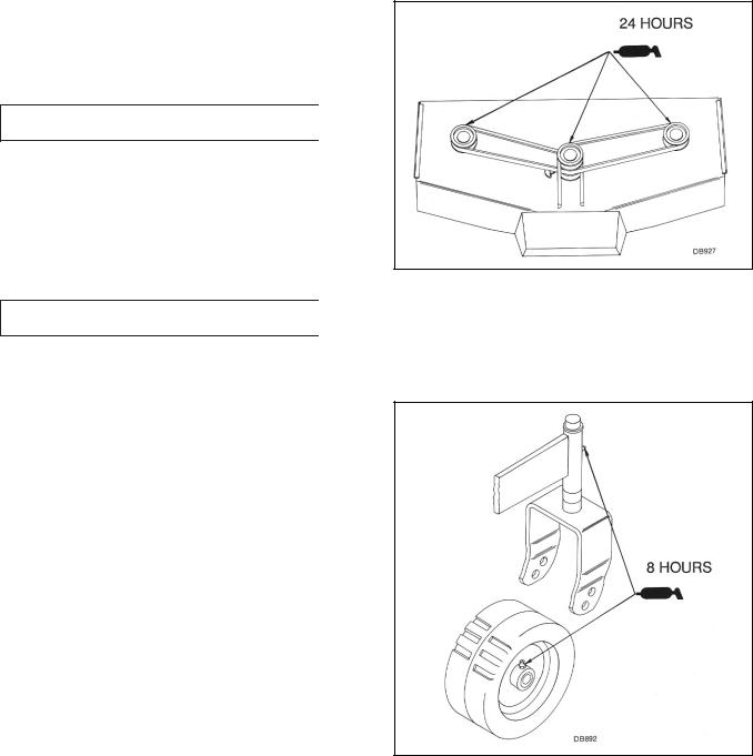
Spindle Lubrication
There are grease zerks on each of the three blade spindles. They are accessible without shield removal. Grease each spindle every 24 hours of operation with a good grade light-to-medium grease gun.
NOTICE
■ Do not over-grease spindles. Excess grease could be transferred to the belt and cause slippage or premature failure.
Figure 3. Spindle Lubrication
Caster Lubrication
Lubricate the caster pivot and caster wheel every eight hours of operation.
Figure 4. Caster Lubrication
BLADE SERVICING
Inspect blades before each use to determine that they are securely fastened and in good condition. Replace any blade that is bent, excessively nicked, worn, or has any other damage. Small nicks can be ground out when sharpening.
12 Owner Service |
15148 (Rev. 2/9/2007) |
|
|
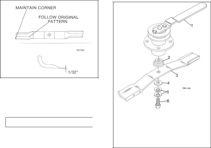
Sharpening
NOTICE
■ When sharpening blades, be sure to balance them. Unbalanced blades will cause excessive vibration which can damage blade spindle bearings. Vibration may also cause structural cracks in mower housing.
Figure 5. Blade Sharpening
Remove blades. Always sharpen both ends at the same time to maintain balance. Follow the original sharpening pattern. Do not sharpen blade to a razor edge. Leave from 1/32" to 1/16" blunt edge. Do not sharpen backside.
A CAUTION
■ Your dealer can supply genuine replacement blades. Substitute blades may not meet original equipment specifications and may be dangerous.
Removal and Installation
Wedge a block of wood between blade and mower housing, or install blade wrench over spindle pulley bolts to prevent spindle from rotating while removing bolts. Loosen the Nylok blade bolt, which has left hand threads.
L59 Removal
Remove the bolt, two cup washers, flat washers and blade. The shoulder washer will not normally come off the machine unless intentionally removed.
L59 Installation
Install shoulder washer (if removed) small end up.
Position blade. Be sure cutting edge is positioned to lead in counter-clockwise rotation, as viewed from top of mower.
Install flat washer, cup washers and bolt. Torque bolt to 170 lbs-ft.
Excessive blade slippage can cause the cup washers to burn and lose their clamping force. If this happens, the cup washers must be replaced.
1.Blade Wrench
2.Shoulder Washer
3.Blade
4.Flat Washer
5.Cup Washer
6.Bolt (special, left hand threads)
Figure 6. Blade Assembly
L306 Removal
Remove bolt, special heat-treated washer, sleeve, cup washers, shim washer, blade, blade stop and clutch disc. The shoulder washer will not normally come off the machine unless intentionally removed.
15148 (Rev. 2/9/2007) |
Owner Service 13 |
|
|
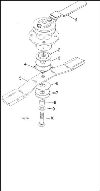
1.Blade Wrench
2.Shoulder Washer
3.Clutch Disc
4.Blade Stop
5.Blade
6.Shim Washer
7.Cup Washers
8.Sleeve
9.Washer (special)
10.Bolt (special, left hand threads)
Figure 7. Blade Assembly L306
L306 Installation
Assemble shoulder washer (small end up, if removed), clutch disc, blade stop and blade. Ensure cutting edge is positioned to lead in counter-clockwise rotation, as viewed from top of mower.
Position shim under blade. Install cup washers sleeve, special heat-treated washer, and special Nylok bolt.
Shims should be added to blade installation to leave approximately 1/32" cup in the cup washers when blade bolt is torqued to 170 lbs-ft.
Excessive blade slipping can cause the cup washers to burn and lose their clamping force. If this happens, the cup washers must be replaced.
The L306 mower blades have friction clutch discs. The clutch is designed to slip only when striking a solid object. If slippage occurs during normal mowing, it may be necessary to add a thin shim washer over sleeve.
Belt Replacement
One of the major causes of belt failure is improper installation. Before a new belt is installed, check pulley shafts and bearings for wear. Check pulley grooves for cleanliness. Make sure spindles turn freely and without wobble.
If grooves require cleaning, moisten a cloth with a nonflammable, non-toxic degreasing agent or commercial detergent and water.
Avoid excessive force during installation.
Do not use tools to pry belt into pulley groove. Do not roll belt over pulleys to install. This can cause hidden damage and premature belt failure.
Refer to Assembly instructions section, page 20, for belt installation.
CLEANING
After Each Use
●Remove large debris such as clumps of dirt, grass, crop residue, etc. from machine.
●Inspect machine and replace worn or damaged parts.
●Replace any safety decals that are missing or not readable.
Periodically or Before Extended Storage
●Clean large debris such as clumps of dirt, grass, crop residue, etc. from machine.
●Remove the remainder using a low-pressure water spray.
1.Be careful when spraying near scratched or torn safety decals or near edges of decals as water spray can peel decal off surface.
2.Be careful when spraying near chipped or scratched paint as water spray can lift paint.
3.If a pressure washer is used, follow the advice of the pressure washer manufacturer.
●Inspect machine and replace worn or damaged parts.
●Sand down scratches and the edges of areas of missing paint and coat with Woods spray paint of matching color (purchase from your Woods dealer).
●Replace any safety decals that are missing or not readable (supplied free by your Woods dealer). See Safety Decals section for location drawing.
14 Owner Service |
15148 (Rev. 2/9/2007) |
|
|

DEALER SERVICE
The information in this section is written for dealer service personnel. The repair described herein requires special skills and tools. If your shop is not properly equipped or your mechanics are not properly trained in this type of repair, you may be time and money ahead to replace complete assemblies.
A WARNING
■Before working underneath, block mower securely. Hydraulic system leak down and failure of mechanical or hydraulic system can cause equipment to drop.
■Keep all persons away from operator control area while performing adjustments, service or maintenance.
A CAUTION
■ Always wear relatively tight and belted clothing to avoid entanglement in moving parts. Wear sturdy, rough-soled work shoes and protective equipment for eyes, hands, hearing and head.
BLADE SPINDLE REPAIR
Removal
Remove blade from spindle. Remove belt shield. Remove belt from pulleys.
Disassemble split taper bushing (located on top of pulley) by removing the two bolts and inserting them into the threaded holes in bushing flange. Tighten bolts alternately to remove split taper bushing. Remove key and pulley.
Remove four bolts attaching spindle to mower frame and remove spindle.
Repair Tips
As a reference point, the grease fitting is in the top portion of spindle housing.
To minimize wear, bearing cups, cones and sleeves are press fit to shaft and will require a press of similar device for removal.
When disassembling, support housing casting to prevent damage. Remove bearing cups by placing a punch in housing slots and driving out. Alternate punch
positions from side to side. Use care to prevent housing damage.
Permatex 3D Aviation Form-A-Gasket® or equivalent is recommended as a sealant for spindle repair.
Disassembly
Drive spring pin (5) out of spindle shaft (9). Support spindle in a press and push shaft (9) down through housing (2). Remove seals from housings. Remove bearing cups from housings. Remove bearing cone from spindle shaft.
Assembly
Bearing cups and cones are designed to work together. It is important to position them so bearing cone taper mates with bearing cup taper.
Lubricate new cups (7) with a light oil. Place them in spindle housing (2) so they will mate with cones (6). Seat cups (7) against machined shoulder of housing with a press or by placing a large soft drift on the flat lip and driving them into housing.
Place bottom bearing cone (6) onto spindle shaft (9) with taper up. Seat on bottom shoulder of shaft with a press.
Insert shaft and bearing cone assembly through bottom of housing (2). Fill housing cavity with a lithium grease of #2 consistency with a MOLY (molybdenum disulfide) additive.
Place top cone (6) on shaft (9), taper down.
Apply a thin coat of Permatex® to shaft area where sleeve (4) will seat.
Insert sleeve (4) on shaft (9) and press sleeve and bearing onto shaft until all bearing free play is removed and there is a slight drag (similar to adjusting the front wheel bearings on an automobile). Check by spinning spindle. It should turn freely.
Be careful not to overtighten bearings. Proper bearing adjustment is essential to good bearing life.
Should you overtighten bearings, hold spindle housing and rap spindle shaft with a lead hammer to loosen bearings. Readjust bearings until proper setting is obtained.
NOTICE
■ Improper positioning of seals can cause seal failure.
15148 (Rev. 2/9/2007) |
Dealer Service 15 |
|
|
 Loading...