


111874 LOADER MOUNTING KIT
for LU126, LU132, 1020, 1027 Loaders
on New Holland® Tractors TN55, TN60A,TN65 TN70, TN70A, TN75, TN75A
and Case IH® Tractors:
JX1060C, JX1070C, JX1075C
includes Hose Kits 58025, 46945, 1010460 1023577, 1023583, 1023584
MAN0041 |
|
SAVE |
THIS |
|
|||
|
|
|
|
|
|||
4/4/2008)(Rev. |
MANUAL! . |
||||||
|
|
|
it |
with |
|||
|
|
|
|
|
|||
|
|
|
|
|
Manual |
||
|
|
Include |
|||||
|
|
|
Loader safety, |
||||
|
|
your |
|
|
|
repair |
|
|
|
It |
containsand |
|
|||
|
|
|
|
informationother |
|||
|
|
|
|
|
|||
|
|
operation, |
in |
||||
|
|
|
part |
|
|||
|
|
|
not |
found . |
|||
|
|
|
|
manuals |
|||
|
|
|
|
|
|
|
|
Tested. Proven. Unbeatable.

 INSTALLATION MANUAL
TO THE DEALER:
Assembly and proper installation of this product is the responsibility of the Woods® dealer. Read manual instructions and safety rules. Make sure all items on the Dealer’s Pre-Delivery and Delivery Check Lists in the Loader Operator’s Manual are completed before releasing equipment to the owner.
TO THE OWNER:
Read this manual and Loader Operator’s Manual before operating your Woods equipment. The information presented will prepare you to do a better and safer job. Keep this manual handy for ready reference. Require all operators to read this manual carefully and become acquainted with all adjustment and operating procedures before attempting to operate. Replacement manuals can be obtained from your dealer. To locate your nearest dealer, check the Dealer Locator at www.WoodsEquipment.com, or in the United States and Canada call 1-800-319-6637.
The equipment you have purchased has been carefully engineered and manufactured to provide dependable and satisfactory use. Like all mechanical products, it will require cleaning and upkeep. Lubricate the unit as specified. Observe all safety information in this manual and safety decals on the equipment.
For service, your authorized Woods dealer has trained mechanics, genuine Woods service parts, and the necessary tools and equipment to handle all your needs.
Use only genuine Woods service parts. Substitute parts will void the warranty and may not meet standards required for safe and satisfactory operation. Record the model number of your equipment in the space provided.
Model: _______________________________ |
Date of Purchase: _____________________ |
Provide this information to your dealer to obtain correct repair parts.
Throughout this manual, the term NOTICE is used to indicate that failure to observe can cause damage to equipment. The terms CAUTION, WARNING, and DANGER are used in conjunction with the Safety-Alert Symbol (a triangle with an exclamation mark) to indicate the degree of hazard for items of personal safety.
2 Introduction
LMK (Rev. 7/20/2007)

SAFETY RULES
ATTENTION! BECOME ALERT! YOUR SAFETY IS INVOLVED!
!LEA EL INSTRUCTIVO!
Si no lee Ingles, pida ayuda a alguien que si lo lea para que le traduzca las medidas de seguridad.
Safety is a primary concern in the design and manufacture of our products. Unfortunately, our efforts to provide safe equipment can be wiped out by an operator’s single careless act.
In addition to the design and configuration of equipment, hazard control and accident prevention are dependent upon the awareness, concern, judgement, and proper training of personnel involved in the operation, transport, maintenance, and storage of equipment.
It has been said, “The best safety device is an informed, careful operator.” We ask you to be that kind of operator.
INSTALLATION
This Loader Mounting Kit is to be used only for the loaders and tractors specified in this manual. Any other use or modification of this mounting kit may result in serious injury or death.
Hydraulics must be connected as instructed in this manual. Do not substitute parts, modify, or connect in any other way.
After connecting hoses, check that all control lever positions function as instructed in the Operator's Manual. Do not put into service until control lever and equipment movements are correct.
Safety instructions are important! Read all attachment and power unit manuals; follow all safety rules and safety decal information. (Replacement manuals and safety decals are available from your dealer. To locate your nearest dealer, check the Dealer Locator at www.WoodsEquipment.com, or in the United States and Canada call 1-800-319- 6637.) Failure to follow instructions or safety rules can result in serious injury or death.
Keep hands and body away from pressurized lines. Use paper or cardboard, not hands or other body parts to check for leaks. Wear safety goggles. Hydraulic fluid under pressure can easily penetrate skin and will cause serious injury or death.
Make sure that all operating and service personnel know that if hydraulic fluid penetrates skin, it
must be surgically removed as soon as possible by a doctor familiar with this form of injury or gangrene, serious injury, or death will result. CONTACT A PHYSICIAN IMMEDIATELY IF FLUID ENTERS SKIN OR EYES. DO NOT DELAY.
Check that all hardware is properly installed. Always tighten to torque chart specifications unless instructed otherwise in this manual.
Air in hydraulic systems can cause erratic operation and allows loads or equipment components to drop unexpectedly. When connecting equipment or hoses or performing any hydraulic maintenance, purge any air in hydraulic system by operating all hydraulic functions several times. Do this before putting into service or allowing anyone to approach the equipment.
Protective hose sleeves must cover all hydraulic hoses within 20 inches of the operator and be secured onto metal hose fittings. Replace hoses or sleeves if damaged or if protective sleeve cannot be properly positioned or secured.
Make sure all hydraulic hoses, fittings, and valves are in good condition and not leaking before starting power unit or using equipment. Check and route hoses carefully to prevent damage. Hoses must not be twisted, bent sharply, kinked, frayed, pinched, or come into contact with any moving parts. Operate moveable components through full operational range to check clearances. Replace any damaged hoses immediately.
Always wear relatively tight and belted clothing to avoid getting caught in moving parts. Wear sturdy, rough-soled work shoes and protective equipment for eyes, hair, hands, hearing, and head; and respirator or filter mask where appropriate.
Do not modify or alter or permit anyone else to modify or alter the equipment or any of its components in any way.
Do not allow bystanders in the area when operating, attaching, removing, assembling, or servicing equipment.
Use a suitable lifting device of sufficient capacity. Use adequate personnel to handle heavy components.
Keep all persons away from operator control area while performing adjustments, service, or maintenance.
Loader Mounting Kit SR3 (4/25/2003)
Safety 3

LOADER MOUNT INSTALLATION
|
CAUTION |
■ Only use 111874 Loader Mounting Kit for mounting Woods LU126, LU132, 1020, 1027 loaders on New Holland® TN55, TN60A TN65, TN70, TN70A, TN75, TN75A tractors and Case IH® JX1060C, JX1070C, and JX1075C tractors. Any other use or modification of this mounting kit may result in serious injury or death.
Safety instructions are important! Read all attachment and power unit manuals; follow all safety rules and safety decal information. (Replacement manuals and safety decals are available from your dealer. To locate your nearest dealer, check the Dealer Locator at www.WoodsEquipment.com, or in the United States and Canada call 1-800-319- 6637.) Failure to follow instructions or safety rules can result in serious injury or death.
Do not modify or alter or permit anyone else to modify or alter the equipment or any of its components in any way.
Always wear relatively tight and belted clothing to avoid getting caught in moving parts. Wear sturdy, rough-soled work shoes and protective equipment for eyes, hair, hands, hearing, and head; and respirator or filter mask where appropriate.
If you do not understand any part of this manual and need assistance, see your dealer.
NOTICE
■ This equipment must be assembled and installed on the customer’s tractor by the Woods dealer. Dealer must thoroughly inspect equipment and complete each item on the PRE-DELIVERY CHECK LIST, DELIVERY CHECK LIST, and PRODUCT REGISTRATION from the loader manual before equipment is released to the customer.
Tractor Preparation |
NOTICE |
For installing this mounting kit, references to right, left, |
■ Clean threaded holes in the tractor chassis |
forward, and rearward directions are determined from |
thoroughly, using a tap of the proper size. Paint, |
the operator’s position in the tractor seat. |
rust, or debris in the threads may not permit cap |
1. Remove the tractor front weights and front fend- |
screws to be installed and tightened correctly. |
|
|
ers, if equipped. |
|
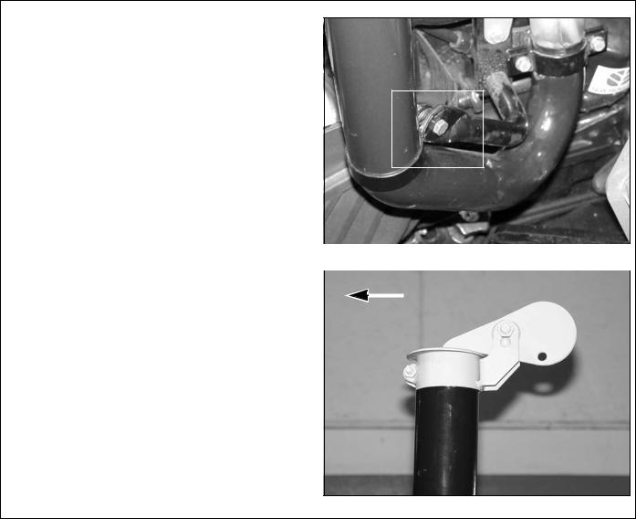
2. Rotate the exhaust pipe opening to face away |
|
from the left side of the tractor. |
|
NOTE: On TNA models the tip of the exhaust |
|
pipe will have to be removed and a weather cap |
|
installed. See page 6 for installation instructions. |
|
3. Set the tractor wheels to the manufacturer’s |
|
widest recommended spacing. Refer to the |
|
tractor operator’s manual. |
|
|
|
As a valued customer, Woods appreciates your comments. Once loader mount and hydraulic hoses have been installed, please take a few minutes to complete the Loader Mount Evaluation sheet that was supplied with this mount. Your comments will help us continue to bring you quality products.
4 Mount Installation |
MAN0041 (Rev. 4/4/2008) |
|
|

Install Right and Left Rear Mounts
1.Attach right rear mount (1) to tractor.
2.Secure using one cap screw (7) and hardened flat washer (9) in the top hole.
3.Secure to bottom holes using two cap screws (8) and hardened flat washers (9).
4.Secure to forward holes using two cap screws (5) and hardened flat washers (9).
5.Repeat steps to install left rear mount (2). See Figure 2.
6.Tighten all hardware to specifications listed on page 6.
1.1000468 Right rear mount
2.1000469 Left rear mount
5. 307553 M20 x 2.5P x 50 mm HHCS
7.1001377 M20 x 2.5P x 40 mm HHCS
8.21413 M20 x 2.5P x 70 mm HHCS
9.57798 3/4 Hardened flat washer.
7  9
9 
8 
 9
9 
 5
5  9
9 
Figure 1. Right Rear Mount Installed
5  9
9 
 7
7  9
9 
8  9
9

Figure 2. Left Rear Mount Installed
Install Grill Guard (Optional)
1.Install grill guard (4) to front of tractor chassis, using four cap screws (5) and lock washers (6) as shown.
2.Torque hardware to specifications given on page 6.
4.40449 Grill guard
5.307553 M20 x 2.5P x 50 mm HHCS
6. 21531 M20 Lock washer
5  6
6

Figure 3. Grill Guard Installed
MAN0041 (Rev.4/4/2008) |
Mount Installation 5 |
|
|
Torque Hardware |
|
|
|
NOTICE |
||
Torque all hardware to specifications listed below. |
|
■ Check torque value of mount hardware after |
||||
|
|
|
|
10 hours of operation and again after every 50 |
||
|
|
|
|
hours of operation. |
||
|
|
|
|
|
||
|
|
TORQUE SPECIFICATIONS |
|
|
||
|
Ref. |
Cap Screw |
Qty |
Wrench |
Required Torque |
|
|
|
|
|
Size |
|
|
|
7 |
M20 x 2.5P x 40 mm |
2 |
30 mm |
244 lbs-ft. (330 N-m) |
|
|
5 |
M20 x 2.5P x 50 mm |
8 |
30 mm |
244 lbs-ft. (330 N-m) |
|
|
8 |
M20 x 2.5P x 70 mm |
4 |
30 mm |
244 lbs-ft. (330 N-m) |
|
|
|
|
|
|
|
|
|
|
|
|
|
|
|
Install Weather Cap on Exhaust Pipe
NOTE: After the hydraulics and loader are install on the tractor, check the clearance between the top of the exhaust pipe and the loader boom when the loader is raised. If there is interference, a weather cap will need to be installed.
1. |
Remove exhaust pipe from the tractor. Save |
|
|
|
|
|
|
hardware for later use. |
|
|
|
|
|
2. |
Remove approximately 6-inches from the top of |
|
|
|
|
|
|
the exhaust pipe. |
|
|
|
|
|
3. |
Attach exhaust pipe to the tractor. Make sure that |
|
|
|
|
|
|
the support flange on the exhaust pipe is between |
|
|
|
|
|
|
the tractor and the support bracket as shown in |
DP7 |
||||
|
page 6. Secure using hardware previously |
|
|
|
|
|
|
removed. |
|
|
Figure 4. Exhaust Pipe Reinstalled |
||
4. |
Attach weather cap to the top of the exhaust pipe |
|
|
|
|
|
|
|
|
|
|
||
|
with supplied hardware. Position cap hinge to the |
|
|
|
|
|
|
|
|
|
Forward |
|
|
|
rear. See Figure 5. Weather cap is included in the |
|
|
|
|
|
|
|
|
|
|
|
|
|
loader mount kit. |
|
|
|
|
|
DP8
Figure 5. Weather Cap Installed
6 Mount Installation |
MAN0041 (Rev. 4/4/2008) |
|
|

HOSE KIT INSTALLATION

Keep hands and body away from pressurized lines. Use paper or cardboard, not hands or other body parts to check for leaks. Wear safety goggles. Hydraulic fluid under pressure can easily penetrate skin and will cause serious injury or death.
Make sure that all operating and service personnel know that if hydraulic fluid penetrates skin, it must be surgically removed as soon as possible by a doctor familiar with this form of injury or gangrene, serious injury, or death will result. CONTACT A PHYSICIAN IMMEDIATELY IF FLUID ENTERS SKIN OR EYES. DO NOT DELAY.
Air in hydraulic systems can cause erratic operation and allows loads or equipment components to drop unexpectedly. When connecting equipment or hoses or performing any hydraulic maintenance, purge any air in hydraulic system by operating all hydraulic functions several times. Do this before putting into service or allowing anyone to approach the equipment.

Protective hose sleeves must cover all hydraulic hoses within 20 inches of the operator and be secured onto metal hose fittings. Replace hoses or sleeves if damaged or if protective sleeve cannot be properly positioned or secured.
Make sure all hydraulic hoses, fittings, and valves are in good condition and not leaking before starting power unit or using equipment. Check and route hoses carefully to prevent damage. Hoses must not be twisted, bent sharply, kinked, frayed, pinched, or come into contact with any moving parts. Operate moveable components through full operational range to check clearances. Replace any damaged hoses immediately.
58025 Hose Kit Installation - - - - - - - - - - - - - - Page 7 46945 Hose Kit Installation- - - - - - - - - - - - - - Page 11 1010460 Hose Kit Installation - - - - - - - - - - - - Page 16 1023577 Hose Kit Installation - - - - - - - - - - - - Page 19 1023584 Hose Kit Installation - - - - - - - - - - - - Page 22 1023583 Hose Kit Installation - - - - - - - - - - - - Page 24
58025 HOSE KIT
General Description
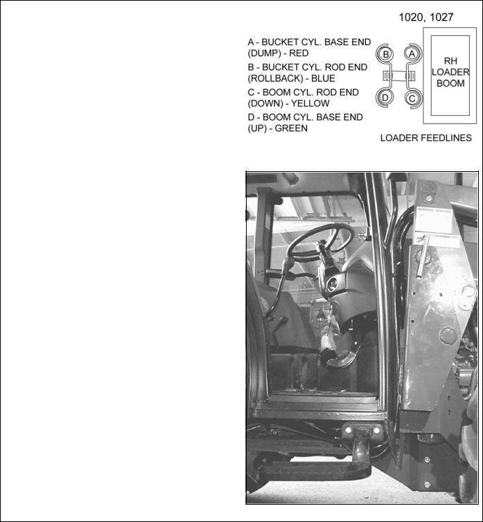
These set up instructions are for operating the 1020, 1027 loader using the tractor hydraulic remote control levers. To use this hydraulic connection the tractor must be equipped with either two hydraulic levers or a joystick control and four tractor hydraulic couplers as shown (Figure 5).
Hydraulic quick couplers for connection to tractor are NOT INCLUDED with hose kits, but are available as service parts.
NOTE: After the hydraulics and loader are installed on the tractor, check the clearance between the top of the exhaust pipe and the loader boom when the loader is raised. If there is interference, a weather cap will need to be installed. See Page 6 for installation instructions.
Figure 6. Connections to Tractor Hydraulic Couplers (Typical)
MAN0041 (Rev. 4/4/2008) |
Hydraulic Installation 7 |
|
|
58025 Hose Kit
Assemble and Route Hoses
1. Attach a 90-degree elbow (2) and male quick coupler (3) to each loader supply hose (1).
2. Connect loader supply hoses to loader feedlines as shown in Figure 7.
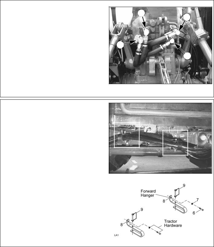
3. Route hydraulic hoses along loader mount, under the right side of operator's platform, and over the rear axle. See Figure 8.
NOTE: Hoses must be routed so that they are not pinched, bent sharply, or chafed during operation. Hoses must not interfere with any tractor control
operation or contact any moving parts.
Figure 7. Loader Feedline Connection
1.53670 Hose, 150" x 3/4 JICM x 3/4 JICM
2.313053 Elbow, 3/4 JICF x 1/2 NPTM 90°
3.-------- Quick coupler, Male (not supplied)
Figure 8. Hose Routing (Typical Installation)
8 Hydraulic Installation |
MAN0041 (Rev. 4/4/2008) |
|
|
58025 Hose Kit
Connect Hoses to Tractor
1.Connect hoses to the tractor hydraulic couplers as shown in Figure 9.
D
C
 B
B
A
CM2683
Figure 9. Hose Connection to Tractor Hydraulic Couplers (Typical)
Install Hose Hangers
1.Install hose hangers beneath the tractor chassis.
NOTE: For forward hanger, use hardware provided in kit; for rearward hanger, use tractor hardware.
2.Route hoses through hose hangers as shown and attach lock pins to retain hoses.
3.Torque hardware to 15 lbs.-ft.
6.30577 M8 x 1.25P x 25 mm HHCS
7.2472 5/16 Lock washer
8.58033 Hose hanger
9. 58047 1/4 x 2-1/2 Lock pin |
Figure 10. Hose Hangers Installed |
Figure 11. Hose Hanger Installation
MAN0041 (Rev. 4/4/2008) |
Hydraulic Installation 9 |
|
|
58025 Hose Kit
Verify Control Movements |
|
|
|
|
|
|
|
|
|
|
|
||
1. |
Mount loader to tractor: Remove mount pins |
|
|
|
|
|
|
from loader uprights. Align tractor with loader and |
|
|
|
|
|
|
slowly drive tractor into loader. Shut off tractor. |
|
|
|
|
|
2. |
Connect loader feedline hoses to tractor remote |
|
|
|
|
|
|
control couplers. See Figure 9. |
|
|
|
|
|
|
|
|
|
Control 2 |
|
|
3. |
|
|
Control 1 |
|
|
|
Comply with all safety rules and start the tractor. |
|
|
|
|
||
|
|
|
|
|
||
|
|
|
|
|
||
4. |
Mount loader to tractor by activating bucket |
|
|
|
|
|
|
cylinders to raise or lower the loader uprights into |
|
|
|
|
|
|
the loader mounts. Slowly advance tractor |
|
|
|
|
|
|
forward, activating appropriate cylinders to |
|
|
|
|
|
|
engage loader completely into mounts. Insert |
|
|
|
|
|
|
mounting pins to secure loader. |
|
|
|
|
|
5.Check that all hydraulic control lever positions operate the loader movements correctly as shown in Figure 12.
6.If loader movements do not respond correctly, shut off tractor, relieve pressure, and reconnect properly. Loader control movements must be correct before proceeding.
7.Once all loader functions are correct, start the tractor and operate the loader to check for leaks. Purge any remaining air from the hydraulic system and check oil level.
DP1
8. When hose routings and |
correct loader |
|
|||
operations are verified, identify each |
circuit |
by |
● Control 1, Handle forward - Boom down |
||
placing a matching colored band around the male |
|||||
● Control 1, Handle back - Boom up |
|||||
and female quick couplers. |
The color-coded |
||||
● Control 2, Handle forward - Dump bucket |
|||||
bands will make reinstallation easier |
when |
the |
|||
or attachment |
|||||
loader is removed from tractor. |
|
|
|
||
|
|
|
● Control 2, Handle back - Rollback bucket |
||
9. Be sure that adequate slack is left in the hoses so |
|||||
or attachment |
|||||
they can move as the loader moves through its |
|||||
|
|||||
full range of motion. |
|
|
|
Figure 12. Tractor Hydraulic Control Levers |
|
|
|
|
|
||
10.Attach the plastic tie straps (included in kit) every 20-inches around the hoses to keep them tightly bundled and away from contact with the ground or other moving parts on the tractor or loader.
11.Before operating the loader, make sure that the Pre-Delivery, Delivery, and Pre-Operation Checklists from the Operator section in the Loader Operator’s Manual have been completed.
10 Hydraulic Installation |
MAN0041 (Rev. 4/4/2008) |
|
|
46945 HOSE KIT
General Description |
|
|
|
|
|
||
These set up instructions are for operating the 1020, |
|
|
|
1027 loader using single lever control valve mounted |
|
|
|
to the loader rear mount as shown in Figure 13. To |
|
|
|
use this hydraulic connection the hoses must be con- |
|
|
|
nected between the control valve and the tractor |
|
|
|
hydraulic system located at the rear of the tractor. |
|
|
|
NOTE: After the hydraulics and loader are install on |
|
|
|
the tractor, check the clearance between the top of |
|
|
|
the exhaust pipe and the loader boom when the |
|
|
|
loader is raised. If there is interference, a weather cap |
|
|
|
will need to be installed. See Page 6 for installation |
|
|
|
instructions. |
|
|
|
NOTICE |
|
|
|
■ If hydraulic lines are not connected as shown |
|
|
|
in this manual, the control valve may be damaged. |
Figure 13. Control Valve Installed |
||
A blocked outlet (RETURN) or improper hose con- |
|||
|
|
||
nection will cause pressurized oil to enter the |
|
|
|
return circuit and damage the valve. |
|
|
|
|
|
|
|
|
|
|
|
Adjust Control Valve |
|
|
|
The control valve comes standard with two OUT |
|
|
|
ports. One at the lower left corner and one at the |
|
|
|
upper right corner. The port at the lower left is shipped |
|
|
|
with a 3/4 JICM x 7/8 O-ring adapter installed. The |
|
|
|
port at the upper right is shipped with a 7/8 O-ring |
|
|
|
plug. |
|
|
|
Remove plug installed in the upper right port. Remove |
|
|
|
adapter from lower left port. Install plug in lower left |
|
|
|
port and adapter in upper right port. Control valve |
|
|
|
should have IN, OUT and PBY ports arranged as |
|
|
|
shown in Figure 14. |
|
|
|
Attach control valve and bracket to loader mount
before proceeding.
Figure 14. Correct Control Valve Arrangement
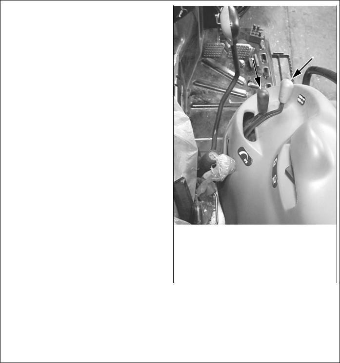
Install Hose Guide
1.Attach hose guide (7) to the outer hole on the bracket in front to the brake peddle.
2.Secure into place using cap screw (8) as shown in Figure 15. Torque to 30 lbs.-ft. using a 16mm wrench.
7.54305 Hose guide
8.307203 M10 x 1.25P x 35 mm HHCS
DP2
Figure 15. Hose Guide Installed
MAN0041 (Rev. 4/4/2008) |
Hydraulic Installation 11 |
|
|
46945 Hose Kit
Attach Hoses to Control Valve
NOTICE
■ If hydraulic lines are not connected as shown in the mount installation manual or tractor manual, the loader control valve may be damaged. A blocked outlet (RETURN) or improper hose connection will cause pressurized oil to enter the return circuit and damage the valve or the tractor hydraulic system.
1.Attach 90° end of hoses (2) to the IN, OUT, and PBY ports on the control valve.
2.Route hoses over hose guide (as shown in Figure 15), under right side of platform, and over right rear axle.
2.46947 Hose, 120” x 3/4 JICF x 7/8 JICF
Figure 16. Control Valve Hose Connections
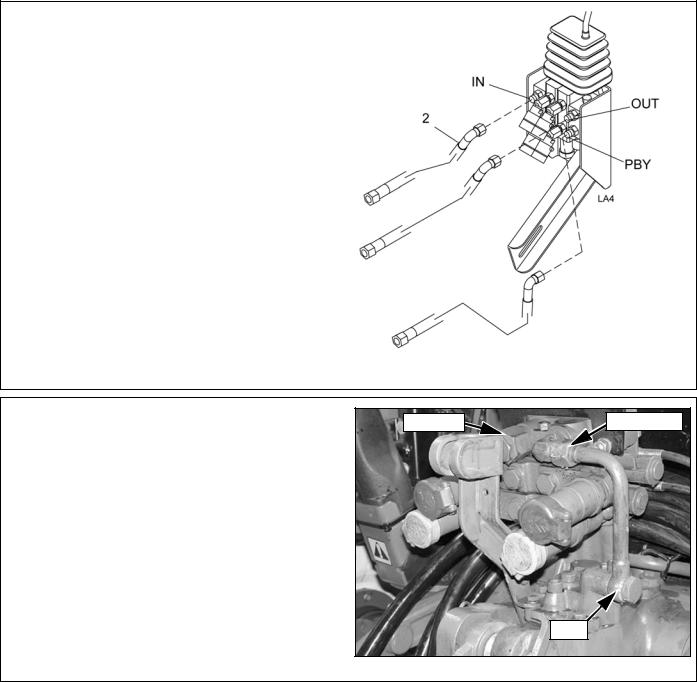
Install Hydraulic Fittings and Hoses
RETURN |
PRESSURE |
1. Locate the hydraulic ports on the rear of the tractor as shown in Figure 17.
2.Remove tube and fittings from the PBY, PRESSURE, and RETURN ports.
PBY DP3
Figure 17. Tractor Hydraulic Connections
12 Hydraulic Installation |
MAN0041 (Rev. 4/4/2008) |
|
|
 Loading...