


ROTARY CUTTERS
RCC42
For Serial Number 1162806 and after
Includes Service and Repair Parts
Information for Serial Number 1162805 and before
MAN0224 |
(Rev. 4/19/2011) |
|
Tested. Proven. Unbeatable. |

 OPERATOR'S MANUAL

TO THE DEALER:
Assembly and proper installation of this product is the responsibility of the Woods® dealer. Read manual instructions and safety rules. Make sure all items on the Dealer’s Pre-Delivery and Delivery Check Lists in the Operator’s Manual are completed before releasing equipment to the owner.
The dealer must complete the online Product Registration form at the Woods Dealer Website which certifies that all Dealer Check List items have been completed. Please contact your dealer to complete this form. Dealers can register all Woods product at dealer.WoodsEquipment.com under Product Registration.
Failure to register the product does not diminish customer’s warranty rights.
TO THE OWNER:
Read this manual before operating your Woods equipment. The information presented will prepare you to do a better and safer job. Keep this manual handy for ready reference. Require all operators to read this manual carefully and become acquainted with all adjustment and operating procedures before attempting to operate. Replacement manuals can be obtained from your dealer. To locate your nearest dealer, check the Dealer Locator at www.WoodsEquipment.com, or in the United States and Canada call 1-800-319-6637.
The equipment you have purchased has been carefully engineered and manufactured to provide dependable and satisfactory use. Like all mechanical products, it will require cleaning and upkeep. Lubricate the unit as specified. Observe all safety information in this manual and safety decals on the equipment.
For service, your authorized Woods dealer has trained mechanics, genuine Woods service parts, and the necessary tools and equipment to handle all your needs.
Use only genuine Woods service parts. Substitute parts will void the warranty and may not meet standards required for safe and satisfactory operation. Record the model number and serial number of your equipment in the spaces provided:
Model: _______________________________ |
Date of Purchase: _____________________ |
Serial Number: (see Safety Decal section for location) ____________________________________
Provide this information to your dealer to obtain correct repair parts.
Throughout this manual, the term NOTICE is used to indicate that failure to observe can cause damage to equipment. The terms CAUTION, WARNING, and DANGER are used in conjunction with the Safety-Alert Symbol (a triangle with an exclamation mark) to indicate the degree of hazard for items of personal safety.
|
|
|
|
2 Introduction |
Gen’l (Rev. 3/5/2010) |
||
|
|
|
|
TABLE OF CONTENTS
INTRODUCTION . . . . . . . . . . . . . . . . . . . . . . . . . . . . . . . . . . . . . . . . . . . . . . 2 SPECIFICATIONS . . . . . . . . . . . . . . . . . . . . . . . . . . . . . . . . . . . . . . . . . . . . . 4 GENERAL INFORMATION . . . . . . . . . . . . . . . . . . . . . . . . . . . . . . . . . . . . . . 4 SAFETY VIDEO ORDER FORM . . . . . . . . . . . . . . . . . . . . . . . . . . . . . . . . . 5-6 SAFETY RULES . . . . . . . . . . . . . . . . . . . . . . . . . . . . . . . . . . . . . . . . . . . . . 7-9 SAFETY DECALS . . . . . . . . . . . . . . . . . . . . . . . . . . . . . . . . . . . . . . . . . . 10-11 OPERATION . . . . . . . . . . . . . . . . . . . . . . . . . . . . . . . . . . . . . . . . . . . . . . . . 12 OWNER SERVICE . . . . . . . . . . . . . . . . . . . . . . . . . . . . . . . . . . . . . . . . . . . 16 TROUBLE SHOOTING . . . . . . . . . . . . . . . . . . . . . . . . . . . . . . . . . . . . . . . . 21 DEALER SERVICE . . . . . . . . . . . . . . . . . . . . . . . . . . . . . . . . . . . . . . . . . . . 22 ASSEMBLY INSTRUCTIONS . . . . . . . . . . . . . . . . . . . . . . . . . . . . . . . . . . . 32 DEALER CHECK LISTS . . . . . . . . . . . . . . . . . . . . . . . . . . . . . . . . . . . . . . . 36 INDEX TO PARTS LISTS . . . . . . . . . . . . . . . . . . . . . . . . . . . . . . . . . . . . . . 37 BOLT TORQUE CHART . . . . . . . . . . . . . . . . . . . . . . . . . . . . . . . . . . . . . . . 48 BOLT SIZE CHART & ABBREVIATIONS . . . . . . . . . . . . . . . . . . . . . . . . . . 49 INDEX . . . . . . . . . . . . . . . . . . . . . . . . . . . . . . . . . . . . . . . . . . . . . . . . . . . . . 50 REPLACEMENT PARTS WARRANTY . . . . . . . . . . . . . . . . . . . . . . . . . . . . 48 PRODUCT WARRANTY . . . . . . . . . . . . . . . . . . . . . . . INSIDE BACK COVER
!LEA EL INSTRUCTIVO!
Si no lee Ingles, pida ayuda a alguien que si lo lea para que le traduzca las medidas de seguridad.
(Rev. 12/22/2006) MAN0224 (Rev. 7/29/2005)
Introduction 3

SPECIFICATIONS
3-Point Hitch. . . . . . . . . . . . . . . . . . . . . . . . . . . . . . . . . . . . . . . . . . Category 1
Cutting Height . . . . . . . . . . . . . . . . . . . . . . . . . . . . . . . . . . . . . . . . . . . . 1" - 9"
Blade Spindle . . . . . . . . . . . . . . . . . . . . . . . . . . . . . . . . . . . . . . . . . . . . . . . . . 1
Number of Blades . . . . . . . . . . . . . . . . . . . . . . . . . . . . . . . . . . . . . . . . . . . . . 2
Blades . . . . . . . . . . . . . . . . . . . . . . . . . . . . . . . . . . . . Heat Treated Alloy Steel
Blade Rotation . . . . . . . . . . . . . . . . . . . . . . . . . . . . . . . . . . . . . . . . . . . . . CCW
Tractor PTO RPM. . . . . . . . . . . . . . . . . . . . . . . . . . . . . . . . . . . . . . . . . . . . 540
Universal Drive. . . . . . . . . . . . . . . . . . . . . . . . . . . . . . . . . . . . . . . . Category 3
Side Frame Thickness . . . . . . . . . . . . . . . . . . . . . . . . . . . . . . . . . . . . . . 11 Ga
Tailwheel . . . . . . . . . . . . . . . . . . . . . . . . . . . . . . . . . . . . . . . . . . . . . . . 4" x 16"
|
RCC42 |
Cutting Width |
42" |
Overall Width |
45" |
Weight (Approximate lbs.) |
350 lbs. |
Blade Speed (Feet per minute) |
11,400 |
Gearbox |
1:1.92 |
Recommended Tractor HP |
15 - 30 |
GENERAL INFORMATION
The purpose of this manual is to assist you in operating and maintaining your cutter. Read it carefully. It furnishes information and instructions that will help you achieve years of dependable performance. These instructions have been compiled from extensive field experience and engineering data. Some information may be general in nature due to unknown and varying operating conditions. However, through experience and these instructions, you should be able to develop procedures suitable to your particular situation.
The illustrations and data used in this manual were current at the time of printing but, due to possible inline production changes, your machine may vary slightly in detail. We reserve the right to redesign and change the machines as may be necessary without notification.

■ Some illustrations in this manual show the cutter with safety shields removed to provide a better view. The cutter should never be operated with any safety shielding removed.
Throughout this manual, references are made to right and left direction These are determined by standing behind the equipment facing the direction of forward travel. Blade rotation is counterclockwise as viewed from the top of the cutter.
4 Introduction |
MAN0224 (Rev. 7/29/2005) |
|
|

Safety Video Order Form
BE SAFE!
BE ALERT!
BE ALIVE!
BE TRAINED
Before Operating Mowers!
Safety Training
Does Make a Difference.
ASSOCIATION OF
EQUIPMENT
MANUFACTURERS
Free Mower Safety Video
Fill out and return the order form and we will send you a FREE VHS or DVD video outlining Industrial and Agricultural Mower Safety Practices. The 22 minute video, developed in cooperation with AEM (Association of Equipment Manufacturers), reinforces the proper procedures to follow while operating your mowing equipment. The video does not replace the information contained in the Operator’s Manual, so please review this manual thoroughly before operating your new mowing equipment.
Safety Video Order Form (8/2/2005)
Safety 5

Also, available from the Association of Equipment Manufacturers:
A large variety of training materials (ideal for groups) are available for a nominal charge from AEM. Following is a partial list:
●Training Package for Rotary Mowers/Cutters-English
Contains: DVD & VHS (English)
Guidebook for Rotary Mowers/Cutters (English)
AEM Industrial/Agricultural Mower Safety Manual (English) AEM Agricultural Tractor Safety Manual (English)
●Training Package for Rotary Mowers/Cutters-English/Spanish
Contains: DVD & VHS (English/Spanish)
Guidebook for Rotary Mowers/Cutters (English/Spanish)
AEM Industrial/Agricultural Mower Safety Manual (English/Spanish) AEM Agricultural Tractor Safety Manual (English/Spanish)
AEM training packages are available through:
AEM at: www.aem.org or
Universal Lithographers, Inc. Email: aem@ulilitho.com 800-369-2310 tel 866-541-1668 fax
Free Mower/Cutter Safety Video Order Form
3 (Select one)
VHS Format - VHS01052 Safety Video
Please send me
DVD Format - DVD01052 Safety Video
Name: ________________________________________ Phone: __________________
Address: _____________________________________
_____________________________________
_____________________________________
Mower/Cutter Model: ______________________ Serial #: ________________________
Send to: ATTENTION: DEALER SERVICES
WOODS EQUIPMENT COMPANY
PO BOX 1000
OREGON IL 61061-1000
USA
6 Safety
Safety Video Order Form (Rev. 2/6/2006)

SAFETY RULES
ATTENTION! BECOME ALERT! YOUR SAFETY IS INVOLVED!
Safety is a primary concern in the design and manufacture of our products. Unfortunately, our efforts to provide safe equipment can be wiped out by an operator’s single careless act.
In addition to the design and configuration of equipment, hazard control and accident prevention are dependent upon the awareness, concern, judgement, and proper training of personnel involved in the operation, transport, maintenance and storage of equipment.
It has been said “The best safety device is an informed, careful operator.” We ask you to be that kind of operator.
TRAINING
Safety instructions are important! Read all attachment and power unit manuals; follow all safety rules and safety decal information. (Replacement manuals and safety decals are available from your dealer. To locate your nearest dealer, check the Dealer Locator at www.WoodsEquipment.com, or in the United States and Canada call 1-800-319- 6637.) Failure to follow instructions or safety rules can result in serious injury or death.
If you do not understand any part of this manual and need assistance, see your dealer.
Know your controls and how to stop engine and attachment quickly in an emergency.
Operators must be instructed in and be capable of the safe operation of the equipment, its attachments, and all controls. Do not allow anyone to operate this equipment without proper instructions.
Never allow children or untrained persons to operate equipment.
PREPARATION
Check that all hardware is properly installed. Always tighten to torque chart specifications unless instructed otherwise in this manual.
Always wear relatively tight and belted clothing to avoid entanglement in moving parts. Wear sturdy, rough-soled work shoes and protective equipment for eyes, hair, hands, hearing, and head; and respirator or filter mask where appropriate.
Make sure attachment is properly secured, adjusted, and in good operating condition.
Make sure spring-activated locking pin or collar slides freely and is seated firmly in tractor PTO spline groove.
If equipped with driveline guard tether chains, make sure they are attached to the tractor and equipment as shown in the pamphlet that accompanies the driveline. Replace if damaged or broken. Check that driveline guards rotate freely on driveline before putting equipment into service.
Power unit must be equipped with ROPS or ROPS cab and seat belt. Keep seat belt securely fastened. Falling off power unit can result in death from being run over or crushed. Keep foldable ROPS systems in “locked up” position at all times.
Before putting equipment into service, check and adjust driveline length as instructed in Operator's Manual. Driveline must not bottom out or pull apart throughout the full range of the tractor hitch. Do not operate until driveline length is correct.
Inspect chain, rubber, or steel band shielding before each use. Replace if damaged.
Remove accumulated debris from this equipment, power unit, and engine to avoid fire hazard.
Make sure all safety decals are installed. Replace if damaged. (See Safety Decals section for location.)
Make sure shields and guards are properly installed and in good condition. Replace if damaged.
A minimum 20% of tractor and equipment weight must be on the tractor front wheels when attachments are in transport position. Without this weight, tractor could tip over, causing personal injury or death. The weight may be attained with a loader, front wheel weights, ballast in tires or front tractor weights. Weigh the tractor and equipment. Do not estimate.
Inspect and clear area of stones, branches, or other hard objects that might be thrown, causing injury or damage.
OPERATION
Do not allow bystanders in the area when operating, attaching, removing, assembling, or servicing equipment.
(Safety Rules continued on next page)
RCC42 (Rev. 7/29/2005) |
Safety 7 |
|
|

SAFETY RULES
ATTENTION! BECOME ALERT! YOUR SAFETY IS INVOLVED!
(Safety Rules continued from previous page)
Full chain, rubber, or steel band shielding must be installed when operating in populated areas or other areas where thrown objects could injure people or damage property.
•If this machine is not equipped with full chain, rubber, or steel band shielding, operation must be stopped when anyone comes within 300 feet (92 m).
•This shielding is designed to reduce the risk of thrown objects. The mower deck and protective devices cannot prevent all objects from escaping the blade enclosure in every mowing condition. It is possible for objects to ricochet and escape, traveling as much as 300 feet (92 m).
Never direct discharge toward people, animals, or property.
Do not operate or transport equipment while under the influence of alcohol or drugs.
Operate only in daylight or good artificial light.
Keep hands, feet, hair, and clothing away from equipment while engine is running. Stay clear of all moving parts.
Always comply with all state and local lighting and marking requirements.
Never allow riders on power unit or attachment.
Power unit must be equipped with ROPS or ROPS cab and seat belt. Keep seat belt securely fastened. Falling off power unit can result in death from being run over or crushed. Keep foldable ROPS systems in “locked up” position at all times.
Always sit in power unit seat when operating controls or starting engine. Securely fasten seat belt, place transmission in neutral, engage brake, and ensure all other controls are disengaged before starting power unit engine.
Operate tractor PTO at 540 RPM. Do not exceed.
Connect PTO driveline directly to power unit PTO shaft. Never use adapter sleeves or adapter shafts. Adapters can cause driveline failures due to incorrect spline or incorrect operating length and can result in personal injury or death.
Look down and to the rear and make sure area is clear before operating in reverse.
Do not operate or transport on steep slopes.
Do not stop, start, or change directions suddenly on slopes.
Use extreme care and reduce ground speed on slopes and rough terrain.
Watch for hidden hazards on the terrain during operation.
Stop power unit and equipment immediately upon striking an obstruction. Turn off engine, remove key, inspect, and repair any damage before resuming operation.
Leak down or failure of mechanical or hydraulic system can cause equipment to drop.
TRANSPORTATION
Always comply with all state and local lighting and marking requirements.
Never allow riders on power unit or attachment.
Do not operate PTO during transport.
Watch for hidden hazards on the terrain.
A minimum 20% of tractor and equipment weight must be on the tractor front wheels when attachments are in transport position. Without this weight, front tractor wheels could raise up resulting in loss of steering. The weight may be attained with front wheel weights, ballast in tires or front tractor weights. Weigh the tractor and equipment. Do not estimate.
Power unit must be equipped with ROPS or ROPS cab and seat belt. Keep seat belt securely fastened. Falling off power unit can result in death from being run over or crushed. Keep foldable ROPS system in “locked up” position at all times.
Do not operate or transport on steep slopes.
Do not operate or transport equipment while under the influence of alcohol or drugs.
MAINTENANCE
Before performing any service or maintenance, disconnect driveline from tractor PTO.
Before working underneath, disconnect driveline, raise cutter, and block cutter securely. Hydraulic system leak down and failure of mechanical or hydraulic system can cause equipment to drop.
Do not modify or alter or permit anyone else to modify or alter the equipment or any of its components in any way.
Always wear relatively tight and belted clothing to avoid entanglement in moving parts. Wear sturdy, rough-soled work shoes and protective
8 Safety |
RCC42 (Rev. 7/29/2005) |
|
|

SAFETY RULES
ATTENTION! BECOME ALERT! YOUR SAFETY IS INVOLVED!
equipment for eyes, hair, hands, hearing, and head; and respirator or filter mask where appropriate.
Make sure attachment is properly secured, adjusted, and in good operating condition.
Keep all persons away from operator control area while performing adjustments, service, or maintenance.
Make certain all movement of equipment components has stopped before approaching for service.
Frequently check blades. They should be sharp, free of nicks and cracks, and securely fastened.
Do not handle blades with bare hands. Careless or improper handling may result in serious injury.
Your dealer can supply genuine replacement blades. Substitute blades may not meet original equipment specifications and may be dangerous.
Tighten all bolts, nuts and screws to torque chart specifications. Check that all cotter pins are installed securely to ensure equipment is in a safe condition before putting unit into service.
Make sure all safety decals are installed. Replace if damaged. (See Safety Decals section for location.)
Make sure shields and guards are properly installed and in good condition. Replace if damaged.
Leak down or failure of mechanical or hydraulic system can cause equipment to drop.
STORAGE
Block equipment securely for storage.
Keep children and bystanders away from storage area.
Follow manual instructions for storage.
RCC42 (Rev. 7/29/2005) |
Safety 9 |
|
|
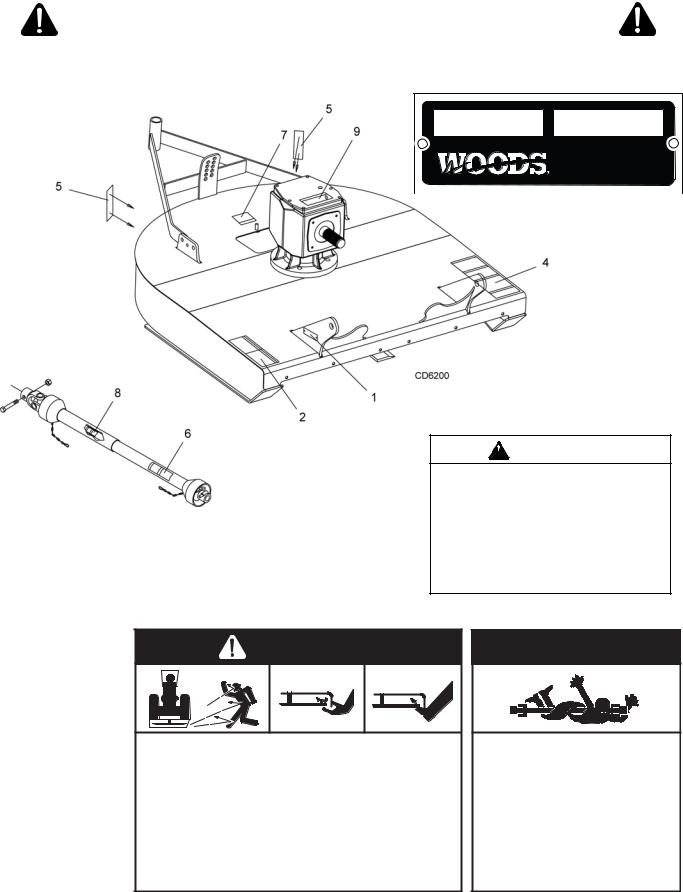
SAFETY & INSTRUCTIONAL DECALS
ATTENTION! BECOME ALERT! YOUR SAFETY IS INVOLVED!
Replace Immediately If Damaged!
1 - SERIAL NUMBER PLATE
MODEL NO. |
SERIAL NO. |
|
Woods Equipment Company |
|
Oregon, Illinois, U.S.A. |
5 - PN 20106
RED REFLECTOR 9"
WARNING
ROTATING COMPONENTS
Do not operate without cover in place.
Look and listen for rotation. Do not open cover until all components have stopped.
|
CONTACT WITH ROTATING PARTS |
7- PN 15502 |
CAN CAUSE SERIOUS INJURY. |
15502--B |
2 - PN 1006682 |
DANGER |
|
ROTATING BLADES AND
THROWN OBJECTS
Do not put hands or feet under or into mower when engine is running.
Before mowing, clear area of objects that may be thrown by blade.
Keep bystanders away.
Keep guards in place and in good condition.
BLADE CONTACT OR THROWN OBJECTS CAN CAUSE
SERIOUS INJURY OR DEATH.
 DANGER
ROTATING DRIVELINE
CONTACT CAN CAUSE DEATH
KEEP AWAY!
DO NOT OPERATE WITHOUT -
All driveline guards, tractor and equipment shields in place
Drivelines securely attached at both ends
Driveline guards that turn freely on driveline
1006682-A
10 Safety |
MAN0224 (Rev. 5/2/2008) |
|
|

SAFETY & INSTRUCTIONAL DECALS
ATTENTION! BECOME ALERT! YOUR SAFETY IS INVOLVED!
Replace Immediately If Damaged!
4 - PN 1006681 |
8 - PN 33347 |
9 - PN 1004114 |


33347E


 DANGER
If shaft connection is visible, shield is missing. Replace shield before
operating equipment. |
1004114 |
6 - PN 18864
 DANGER
ROTATING DRIVELINE
CONTACT CAN CAUSE DEATH
KEEP AWAY!
DO NOT OPERATE WITHOUT -
All driveline guards, tractor and equipment shields in place
Drivelines securely attached at both ends
Driveline guards that turn freely on
driveline |
18864-C |
|
BE CAREFUL!
Use a clean, damp cloth to clean safety decals.
Avoid spraying too close to decals when using a pressure washer; high-pressure water can enter through very small scratches or under edges of decals causing them to peel or come off.
Replacement safety decals can be ordered free from your Woods dealer. To locate your nearest dealer, check the Dealer Locator at www.WoodsEquipment.com, or in the United States and Canada call 1-800-319-6637.
MAN0224 (Rev. 5/2/2008) |
Safety 11 |
|
|
OPERATION
The operator is responsible for the safe operation of the cutter. The operator must be properly trained. Operators should be familiar with the cutter, the tractor, and all safety practices before starting operation. Read the safety rules and safety decals on pages 3 to 7.
This standard-duty cutter is designed for grass and weed mowing and shredding.
Recommended mowing speed for most conditions is from 2 to 5 mph.

Full chain, rubber, or steel band shielding must be installed when operating in populated areas or other areas where thrown objects could injure people or damage property.
•If this machine is not equipped with full chain, rubber, or steel band shielding, operation must be stopped when anyone comes within 300 feet (92 m).
•This shielding is designed to reduce the risk of thrown objects. The mower deck and protective devices cannot prevent all objects from escaping the blade enclosure in every mowing condition. It is possible for objects to ricochet and escape, traveling as much as 300 feet (92 m).

Never allow riders on power unit or attachment.
Keep bystanders away from equipment.
Make sure spring-activated locking pin or collar slides freely and is seated firmly in tractor PTO spline groove.
Operate tractor PTO at the rpm speed stated in “Specifications” section.
 CAUTION
Stop power unit and equipment immediately upon striking an obstruction. Turn off engine, remove key, inspect, and repair any damage before resuming operation.
Always wear relatively tight and belted clothing to avoid getting caught in moving parts. Wear sturdy, rough-soled work shoes and protective equipment for eyes, hair, hands, hearing, and head; and respirator or filter mask where appropriate.
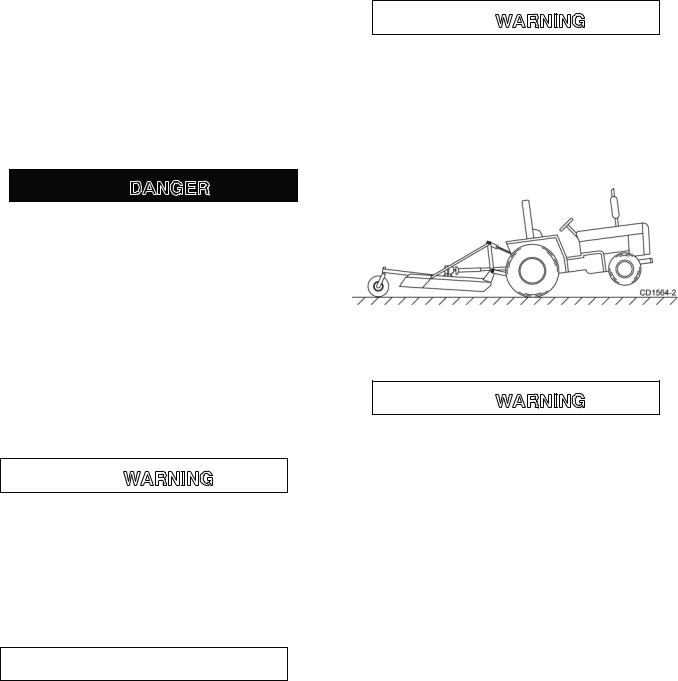
Tractor Stability

A minimum 20% of tractor and equipment weight must be on the tractor front wheels when attachments are in transport position. Without this weight, front tractor wheels could raise up resulting in loss of steering. The weight may be attained with front wheel weights, ballast in tires or front tractor weights. Weigh the tractor and equipment. Do not estimate.
Figure 1. Tractor Stability
ATTACHING CUTTER TO TRACTOR

Make sure spring-activated locking pin or collar slides freely and is seated firmly in tractor PTO spline groove.
■ With cutter adjusted to transport position, set upper stop on tractor lift quadrant to prevent cutter from contacting the driveline when being raised.
1.Attach the cutter hitch pins to the lower tractor lift arms and secure.
2.Attach tractor top link to cutter clevis using forward hole.
3.Check driveline length. See page 34 for instructions on shortening driveline.
4.Connect driveline to tractor PTO shaft.
NOTE: You will need to adjust the top link; refer to Top Link Adjustment, page 13.
NOTE: The standard 1-3/8" 6B spline driveline with a QD yoke is used to connect the cutter to the tractor.
5.Adjust the tractor lower 3-point arm anti-sway devices to prevent cutter from swinging side to side during transport.
6.Adjust tractor drawbar so that it will not interfere with cutter or driveline.
12 Operation |
MAN0224 (Rev. 9/30/2005) |
|
|
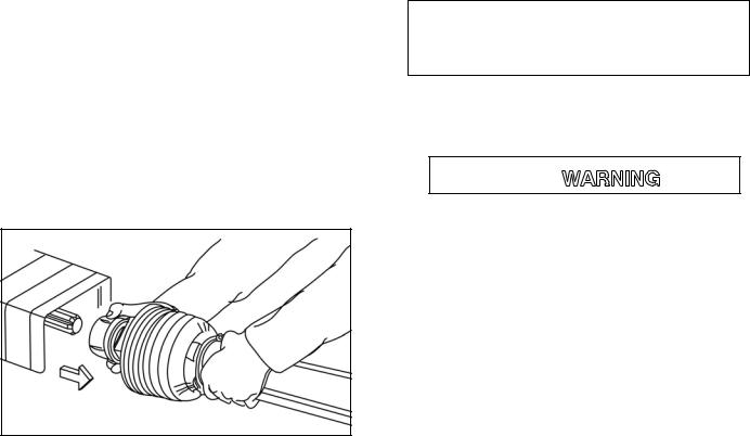
INSTALLATION AND
REMOVAL OF DRIVELINE (TRACTOR PTO)
To Install:
Pull locking collar back and at the same time push driveline onto tractor PTO shaft until locking device engages.
To Remove:
Hold driveline in position, pull locking collar back, and slide driveline off tractor PTO shaft.
Figure 2. Lock Collar
3" - desired cutting height
+ 5.5 - distance blade cutting edge is below deck
=8.5
c. Adjust the front-to-rear attitude from 1/2" to 3/4" higher than the front or from 9" to 9-1/4" at the rear.

Before working underneath, disconnect driveline, raise cutter, and block cutter securely. Hydraulic system leak down and failure of mechanical or hydraulic system can cause equipment to drop.
Keep all persons away from operator control area while performing adjustments, service, or maintenance.
■ Avoid low cutting heights. Striking the ground with blades produces one of the most damaging shock loads a cutter can encounter. Allowing blades to contact ground repeatedly will cause damage to cutter and drive.
SHREDDING
For shredding, set the cutter lower at rear. Determine how much lower to set the rear by experimenting in different situations.
CUTTING HEIGHT ADJUSTMENT
1.Level cutter from side to side. Check by measuring from cutter frame to the ground at each deck rail.
2.Adjust, using tractor 3-point arm leveling device.
NOTE: Keep the front of cutter slightly lower than rear for best mowing.
3.Control cutting height with tractor 3-point arms, rear tailwheel adjustment.
4.To raise rear of cutter, move tailwheel arm down.
5.To raise front of cutter, raise tractor 3-point arms.
The cutting height is the distance between the blade and the ground. The blades are approximately 5.5" below the deck. To check cutting height, do the following:
a.Place a straight edge along top edge of deck.
b.Select a cutting height; as an example, for an approximate cutting height of 3", set the center of the deck 8.5" above the ground.
TOP LINK ADJUSTMENT (FIGURE 3)
1.To mount tractor top link, use lowest hole provided in the tractor’s top link attachment bracket.
2.Select a top link mounting pin that will swing through the cutter A-frame bars and attach rear portion of tractor top link in the first hole of cutter floating link.
3.Raise cutter to transport position and adjust tractor top link until cutter is level in the raised position.
NOTE: Some tractors are equipped with a short top link. If you cannot adjust the cutter level using the middle hole in the cutter floating link, use the front hole and adjust the cutter level in the transport position.
NOTICE
■With cutter adjusted to transport position, set upper stop on tractor lift quadrant to prevent cutter from contacting the driveline when being raised.
■Select a top link pin (maximum length 3-5/8") that will allow floating link to swing freely through the cutter A-frame bars.
MAN0224 (Rev. 9/30/2005) |
Operation 13 |
|
|
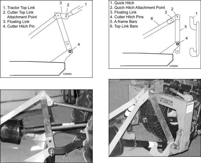
Figure 3. Top Link Adjustment
DP6
Figure 4. 3-Point Arms & Top Link Attached to Cutter
QUICK HITCH ATTACHMENT (FIGURE 5)
1.Remove nut and washer from hitch pin and lower A-frame bars to the second mounting hole.
2.Attach open end of floating link (3) to the A-frame bars (5). Attach closed end of floating link to top link bars (6).
NOTE: Quick hitch top hook will pick up on pin (2). Lower quick hitch hook will attach to cutter hitch pins (4).
3.Raise cutter to transport position and adjust tractor top link until cutter is level in the raised position.
NOTICE
■ With cutter adjusted to transport position, set upper stop on tractor lift quadrant to prevent cutter from contacting the driveline when being raised.
Figure 5. Quick Hitch Adjustment
DP7
Figure 6. Quick Hitch Attached to Cutter
OPERATING TECHNIQUE
1.Power for operating the cutter is supplied by the tractor PTO. Operate PTO at 540 RPM. Know how to stop the tractor and cutter quickly in an emergency.
2.Engage PTO at a low engine RPM to minimize stress on the drive system and gearbox. With PTO engaged, raise PTO speed to 540 RPM and maintain throughout cutting operation.
Gearbox protection is provided by a slip clutch with replacement fiber disc or a shear bolt. The slip clutch is designed to slip and the shear bolt will shear when excessive torsional loads occur.
3.Move slowly into material. Adjust tractor ground speed to provide a clean cut without lugging the tractor engine. Use a slow ground speed for better shredding.
Proper ground speed will depend on the terrain and the material’s height, type, and density.
14 Operation |
MAN0224 (Rev. 9/30/2005) |
|
|

Normally, ground speed will range from 2 to 5 mph. Tall, dense material should be cut at a low speed; thin, medium-height material can be cut at a faster ground speed.
4.Always operate tractor PTO at 540 RPM to maintain proper blade speed and to produce a clean cut.
5.Under certain conditions tractor tires may roll down some grass and prevent cutting at the same height as the surrounding area. When this occurs, reduce your ground speed but maintain PTO at 540 RPM. The lower ground speed will permit grass to rebound partially.
STORAGE

Disconnect cutter driveshaft and secure up off ground. Raise cutter with 3-point hitch. Place blocks under cutter side skids. Lower cutter onto blocks. Disconnect cutter from tractor 3-point hitch and carefully drive tractor away from cutter.
Keep children and bystanders away from storage area.
PRE-OPERATION CHECK LIST
(OWNER'S RESPONSIBILITY)
___ Review and follow all safety rules and safety decal instructions on pages 3 through 7.
___ Check that equipment is properly and securely attached to tractor.
___ Make sure driveline spring-activated locking pin or collar slides freely and is seated firmly in tractor PTO spline groove.
___ Set tractor PTO at 540 RPM.
___ Lubricate all grease fitting locations. Make sure PTO shaft slip joint is lubricated.
___ Check to be sure gear lube runs out the small check plug on side of gearbox.
___ Check that all hardware is properly installed and secured.
___ Check that blades are sharp and secure and cutting edge is positioned to lead in a counterclockwise rotation.
___ Check that shields and guards are properly installed and in good condition. Replace if damaged.
___ Check cutting height, front-to-rear attitude, and top link adjustment.
___ Place tractor PTO and transmission in neutral before starting engine.
___ Inspect area to be cut and remove stones, branches, or other hard objects that might be thrown and cause injury or damage.
MAN0224 (Rev. 9/30/2005) |
Operation 15 |
|
|

OWNER SERVICE
The information in this section is written for operators who possess basic mechanical skills. If you need help, your dealer has trained service technicians available. For your protection, read and follow the safety information in this manual.

Keep all persons away from operator control area while performing adjustments, service, or maintenance.
Before performing any service or maintenance, disconnect driveline from tractor PTO.
Never go underneath equipment (lowered to the ground or raised) unless it is properly blocked and secured. Never place any part of the body underneath equipment or between moveable parts even when the engine has been turned off. Hydraulic system leak down, hydraulic system failures, mechanical failures, or movement of control levers can cause equipment to drop or rotate unexpectedly and cause severe injury or death. Follow Operator's Manual instructions for working underneath and blocking requirements or have work done by a qualified dealer.
 CAUTION
If you do not understand any part of this manual and need assistance, see your dealer.
BLOCKING METHOD
To minimize the potential hazards or working underneath the cutter, follow these procedures.
1.Jackstands with a load rating of 1000 lbs. or more are the only approved blocking device for this cutter. Install a minimum of four jackstands, two in front and two in rear (refer to Xs in Figure 7) under the cutter before working underneath unit.
2.Do not position jackstands under wheels, axles, or wheel supports. Components can rotate and cause cutter to fall.
3.Consider the overall stability of the blocked unit. Just placing jackstands underneath will not ensure your safety.
4.The working surface must be level and solid to support the weight on the jackstands. Make sure
jackstands are stable, both top and bottom. Make sure cutter is approximately level.
5.With full cutter weight lowered onto jackstands, test blocking stability before working underneath.
6.If cutter is attached to tractor when blocking, set the brakes, remove key, and block cutter before working underneath.
7.Securely block rear tractor wheels, in front and behind. Tighten tractor lower 3-point arm anti-sway mechanism to prevent side-to-side movement.
LUBRICATION INFORMATION
1.Do not let excess grease collect on or around parts, particularly when operating in sandy areas.
2.See Figure 7 for lubrication points and frequency of lubrication based on normal operating conditions. Severe or unusual conditions may require more frequent lubrication.
3.Use a lithium grease of #2 consistency with a MOLY (molybdenum disulfide) additive for all locations unless otherwise noted. Be sure to clean fittings thoroughly before attaching grease gun. One good pump of most guns is sufficient when the lubrication schedule is followed.
Driveline Lubrication
1.Lubricate the driveline slip joint every eight operating hours. Failure to maintain proper lubrication could result in damage to U-joints, gearbox, and driveline.
2.Lower cutter to ground, disconnect driveline from tractor PTO shaft, and slide halves apart but do not disconnect from each other.
3.Apply a bead of grease completely around male half where it meets female half. Slide drive halves over each other several times to distribute grease.
Gearbox Lubrication
For gearbox, use a high quality gear oil with a viscosity index of 80W or 90W and an API service rating of GL– 4 or –5 in gearboxes.
Fill gearbox until oil runs out the side plug on gearbox. Check gearbox daily for evidence of leakage, and contact your dealer if leakage occurs.
16 Owner Service |
MAN0224 (Rev. 7/29/2005) |
|
|
 Loading...