

Page 1

PRO ISLAND HOOD
INSTALLATION GUIDE
SPECIFICATIONS, INSTALLATION, AND MORE
Page 2

PRO ISLAND HOOD
Contents
3 Pro Island Hood
4 Specications
6 Installation
10 Blower Specications
11 Troubleshooting
Features and specications are subject to change at any
time without notice. Visit wolfappliance.com/specs for the
most up-to-date information.
Important Note
To ensure this product is installed and operated as safely
and efciently as possible, take note of the following types
of highlighted information throughout this guide:
IMPORTANT NOTE highlights information that is especially
important.
CAUTION indicates a situation where minor injury or product
damage may occur if instructions are not followed.
WARNING states a hazard that may cause serious injury or
death if precautions are not followed.
IMPORTANT NOTE: Throughout this guide, dimensions in
parentheses are millimeters unless otherwise specied.
IMPORTANT NOTE: Save these instructions for the local
electrical inspector.
2 | Wolf Customer Care 800.222.7820
Page 3
PRO ISLAND HOOD
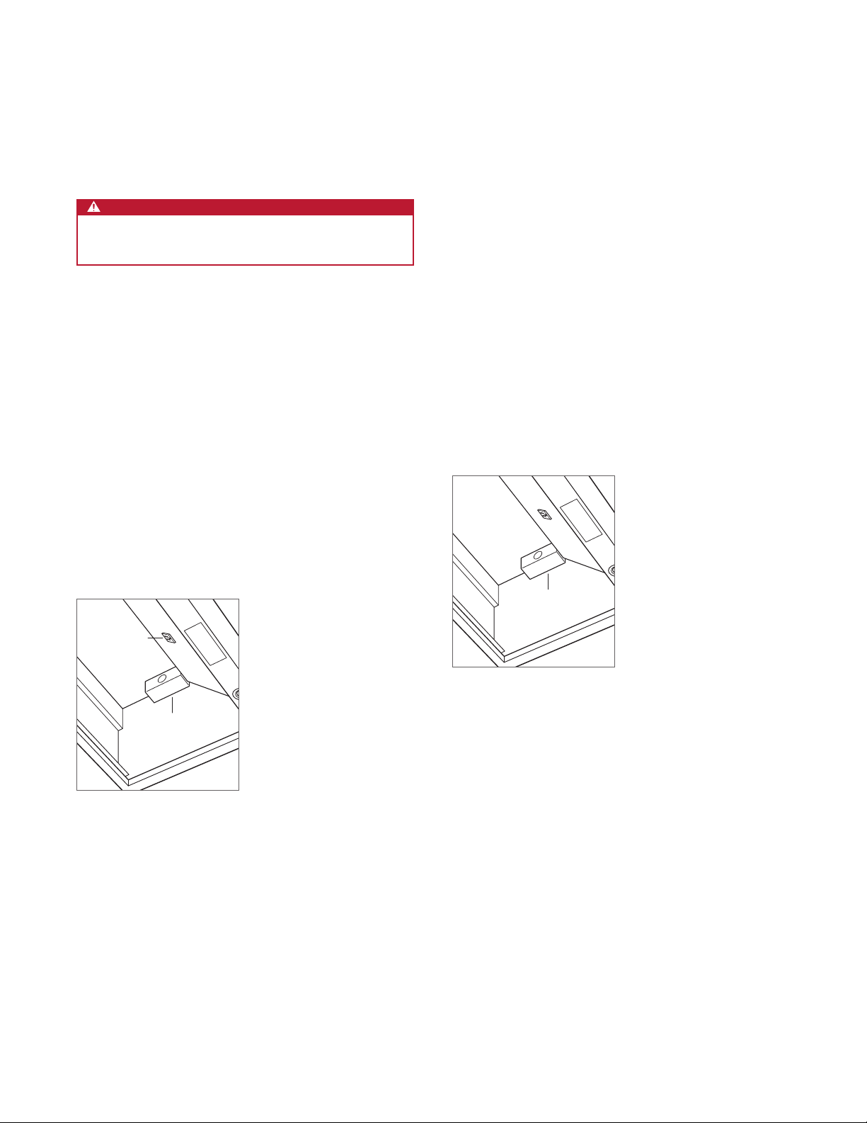
Product Information
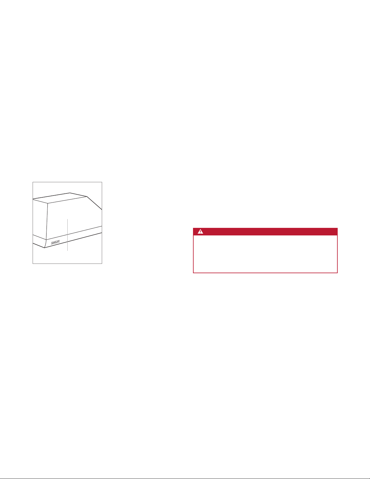
Important product information, including the model and
serial number, are listed on the product rating plate. The
rating plate is located on an inside wall of the hood shell
(lters need to be removed). Refer to the illustration below.
If service is necessary, contact Wolf Factory Certied
Service with the model and serial number. For the name of
the nearest Wolf Factory Certied Service or for questions
regarding the installation, visit the contact and support
section of our website, wolfappliance.com, or call Wolf
Customer Care at 800-222-7820.
RATING PLATE
Rating plate location
IMPORTANT INSTRUCTIONS
TO REDUCE THE RISK OF FIRE, ELECTRIC SHOCK,
OR INJURY, OBSERVE THE FOLLOWING:
• Installation work and electrical wiring must be
done by qualied person(s) in accordance with all
applicable codes and standards, including rerated construction.
• Two installers are recommended due to the size
and weight of the pro hood.
• Install the pro hood only with a blower manufac-
tured by Wolf.
• When cutting or drilling into the wall or ceiling,
do not damage electrical wiring and other hidden
utilities.
• Ducted fans must always be vented to the
outdoors.
CAUTION
To reduce the risk of re and properly exhaust air,
be certain to duct air outside. Do not vent exhaust
air into spaces within walls or ceilings or into
attics, crawl spaces, or garages.
wolfappliance.com | 3
Page 4

SPECIFICATIONS
Installation Requirements
Install the hood 30" (762) to 36" (914) from the bottom of the
hood to the countertop.
BLOWER ASSEMBLIES
Pro Island Hoods require an internal, in-line, or remote
blower assembly, avail able through an authorized Wolf
dealer. For local dealer information, visit the nd a showroom section of our website, wolfappliance.com. Refer to
specic installation instructions provided with each blower
assembly.
DUCT COVER
Optional stainless steel duct covers, in multiple heights, are
available through your authorized Wolf dealer. For local
dealer information, visit the find a showroom section of our
website, wolfappliance.com.
Ducting
WARNING
To reduce the risk of re, use only metal ducting.
IMPORTANT NOTE: Consult a qualied HVAC professional
for specic installation and ducting applications.
Pro Island Hoods accommodate a 10"
only rigid metal ducting.
A straight, short duct run allows the hood to perform most
efciently. If the duct run exceeds 50'
blower may be required to maintain proper air ow.
Internal and in-line blowers require a roof or wall cap.
Connect ducting to the cap or to the remote blower and
work back towards the hood. Use sheet metal screws and
high-temperature duct tape to seal joints between ducting
sections.
Pro Island Hoods include a backdraft damper. Local codes
may require the use of an additional backdraft and/or makeup air damper. Contact your local HVAC professional for
specic requirements.
(254) round duct. Use
(15 m), a higher CFM
A make-up air damper is available through an authorized
Wolf dealer. For local dealer information, visit the nd a
showroom section of our website, wolfappliance.com.
4 | Wolf Customer Care 800.222.7820
Page 5
SPECIFICATIONS
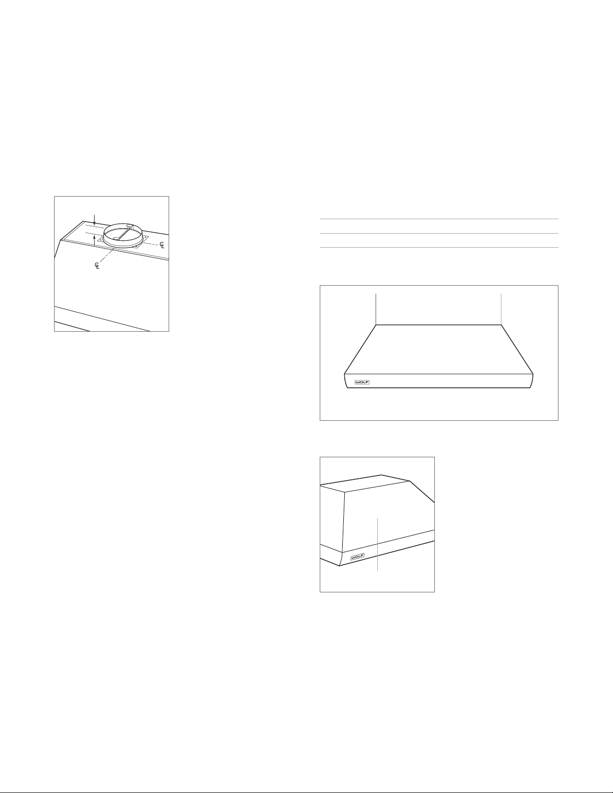
Discharge
Pro Island Hoods have a vertical discharge. Refer to the
illustration below.
2" (51)
Vertical discharge
Electrical Requirements
Installation must comply with all applicable electrical codes.
Locate the electrical supply as shown in the illustration
below. A separate circuit servicing only this appliance is
required.
ELECTRICAL REQUIREMENTS
Electrical Supply grounded, 120 VAC, 60 Hz
Service 15 amp dedicated circuit
ELECTRICAL LOCATION
THROUGH TOP OF HOOD
30" (762) TO 36" (914) BOTTOM EDGE TO COUNTERTOP
Electrical location
RATING PLATE
Rating plate location
wolfappliance.com | 5
Page 6
INSTALLATION
Hood Preparation
Remove the lters prior to installation. To remove, press
the lter upward and rotate the bottom. Remove the grease
cups from the bottom edge of the hood. Refer to the illustration below.
GREASE
CUP
SPRING
FILTER
SIDE VIEW
Filters
Installation
WARNING
Ceiling framing must be able to support the weight of
the hood and internal blower, if applicable.
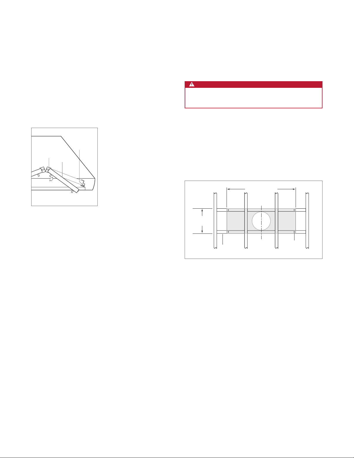
1 Refer to the illustration below for typical ceiling framing.
Additional framing or blocking is required in the
mounting location of the hood.
13"
(330)
5
/32" (4) diameter holes in the ceiling framing to
TOP PLATE WIDTH
2 Drill four
match the mounting holes in the corners of the hood’s
top plate.
BLOCKING
Ceiling framing (typical)
C
L
MOUNTING
HOLE
6 | Wolf Customer Care 800.222.7820
Page 7
INSTALLATION
Installation
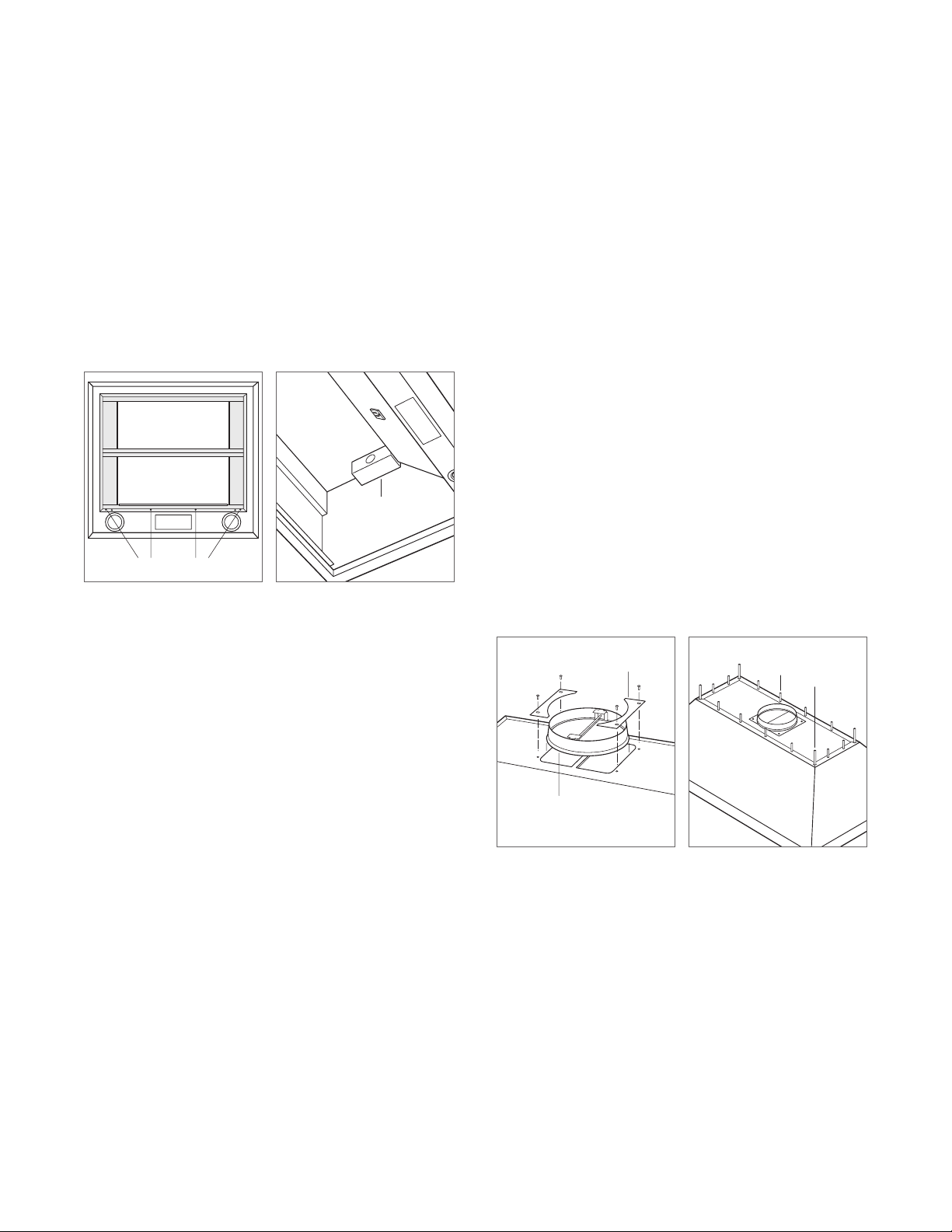
3 Remove the hood’s internal frame indicated by the
shaded area. Remove only the four screws indicated in
the illustration below.
4 Remove the electrical box from the inside the hood.
Refer to the illustration below.
ELECTRICAL
BOX
REMOVE SCREWS
Internal frame Electrical box
5 Remove the transition, hold-down brackets, and screws
from the packaging and use the hold-down brackets and
screws to secure the transition to the top of the hood.
Refer to the illustration below.
6 Lift the hood into position aligning the hood mounting
holes with the pre-drilled holes in the ceiling framing.
Install the four provided lag screws with washers through
each corner of the top plate and into the ceiling framing.
Refer to the illustration below.
7 Install the provided hex head screws through the
remaining holes in the hood’s top plate and into the
ceiling framing.
8 Insert Romex
®
wire(s) into the electrical knockout and
secure with the provided connector.
9 Connect the ducting to the transition and secure with
duct sealing tape.
10 Reinstall the internal frame.
HOLD-DOWN
BRACKET
HEX HEAD
SCREW LAG
SCREW
TRANSITION
Transition mounting Hood installation
wolfappliance.com | 7
Page 8
INSTALLATION
Electrical Connections
WARNING
Before making electrical connections, verify the power
is turned off at the service panel.
IMPORTANT NOTE: Refer to installation instructions pro-
vided with the blower assembly.
INTERNAL BLOWER
1 Connect black to black and white to white with the
provided connectors, and connect the green/bare wire
to the ground screw.
2 Verify all wires are secure and not pinched, and reinstall
the box.
3 Plug the blower power cord into the receptacle inside
the hood. Refer to the illustration below.
4 Turn on the power to the hood and verify light and
blower operation.
IN-LINE/REMOTE BLOWER
1 Remove the connector from the end of the orange wire.
2 Connect the home supply. Connect black to black and
connect the green/bare wire to the ground screw.
3 Connect the blower supply. Connect black to orange,
all three white wires, and connect the green/bare wire to
the ground screw.
4 Verify all wires are secure and not pinched, and reinstall
the box.
5 Turn on the power to the hood and verify light and
blower operation.
ELECTRICAL
BOX
RECEPTACLE
ELECTRICAL
BOX
Electrical connections
Electrical connections
8 | Wolf Customer Care 800.222.7820
Page 9
INSTALLATION
Complete the Installation
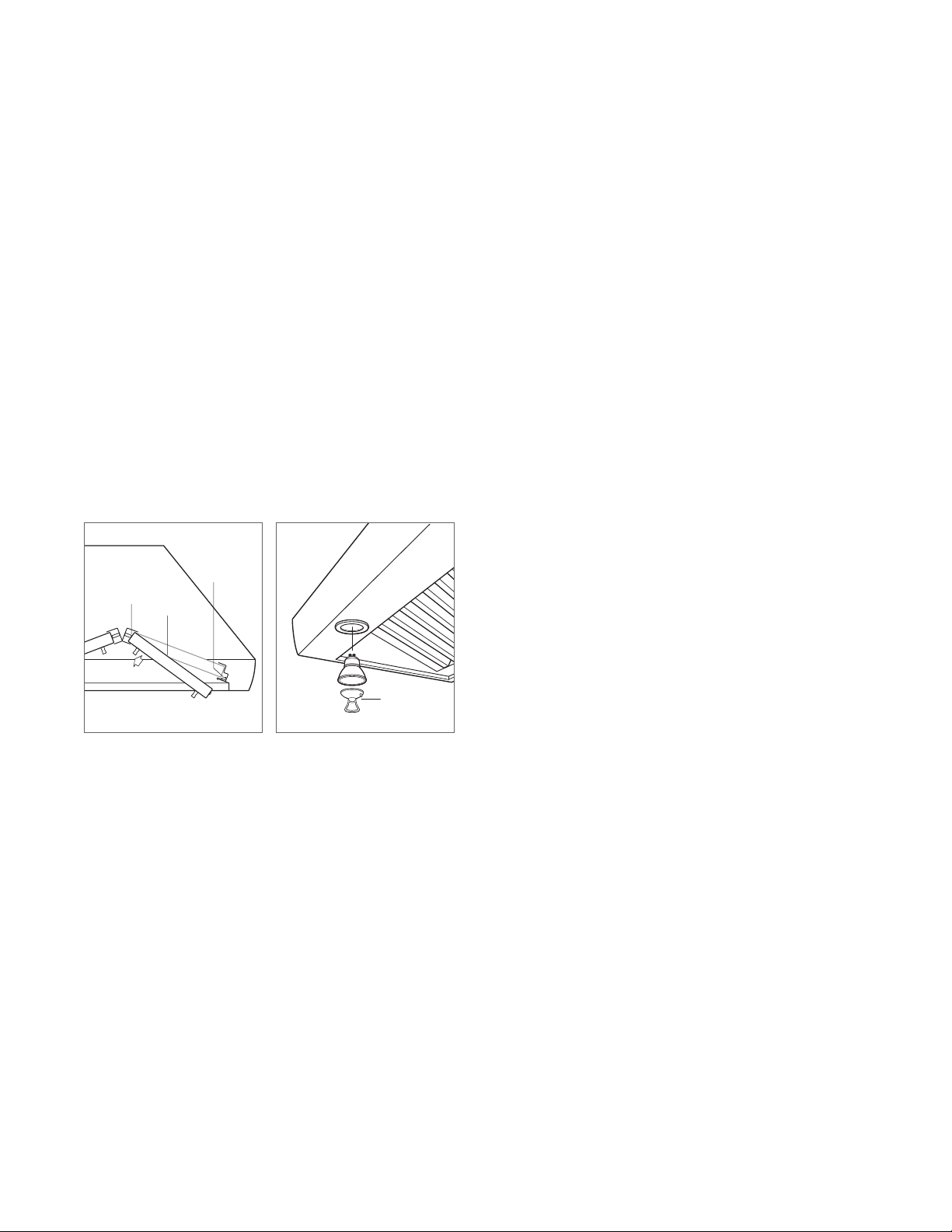
FILTERS
Install the grease cups at the bottom edges of the hood.
Orient the lters with the lines running vertically. To install,
place the top edge of the lter against the spring, press
upward and rotate the bottom. Refer to the illustration
below.
LIGHT BULBS
A suction-cup-style light bulb changer is provided with
the hood. To install, use the changer to push the bulb into
the receptacle and rotate counterclockwise one-quarter
turn. Refer to the illustration below.
GREASE
CUP
SPRING
FILTER
WOLF LOGO
To attach the Wolf logo, clean the mounting area with
rubbing alcohol. Remove the paper backing, position the
logo parallel with the bottom of the hood, and press into
place.
LIGHT BULB
SIDE VIEW
Filters Light bulb installation
CHANGER
wolfappliance.com | 9
Page 10
BLOWER SPECIFICATIONS
28
29
29
11
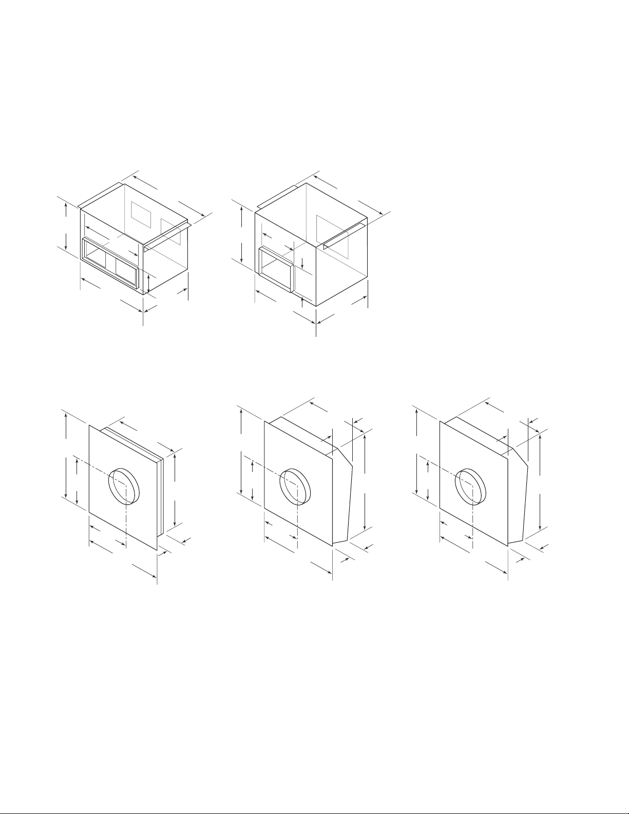
Blower Dimensions
IN-LINE BLOWERS
243/8"
(619)
3
/4"
(298)
181/2"
(470)
41/2"
(114)
211/2"
(546)
121/4"
(311)
18"
(457)
12"
(305)
22"
(559)
8"
(203)
24
(632)
18"
(457)
7
/8
"
600 CFM in-line blower
1100 CFM in-line blower
REMOTE BLOWERS
18" (457)
10"
(254)
29
(749)
7
(184)
1
/2
"
(749)
1
/2
"
1
/4
"
14
(375)
10" (254)
DIAMETER
3
/4
"
3
/8
10
"
(264)
25"
(635)
1
(718)
/4
15
(394)
3
/4
20
"
24
(629)
(527)
1
/2
24
"
(622)
3
/4
4
3
/4
"
(121)
"
"
10" (254)
DIAMETER
1
/2
"
14"
(356)
1
(749)
/2
14
(375)
"
10" (254)
DIAMETER
3
/4
"
1
/8
10
"
(257)
22"
(559)
600/900 CFM remote blower 1200 CFM remote blower 1500 CFM remote blower
21" (533)
10"
(254)
29
(749)
7
(184)
1
/2
"
1
/4
"
10 | Wolf Customer Care 800.222.7820
Page 11

TROUBLESHOOTING
Troubleshooting
IMPORTANT NOTE: If the hood does not operate properly,
follow these troubleshooting steps:
• Verify electrical power is supplied to the hood.
• Verify proper wiring connections.
• If the hood does not operate properly, contact Wolf
Factory Certied Service. Do not attempt to repair the
hood. Wolf is not responsible for service required to
correct a faulty installation.
Sub-Zero, Sub-Zero & Design, Sub-Zero & Snowake Design, Dual Refrigeration, The Living Kitchen, Great American Kitchens The Fine Art of Kitchen Design, Wolf, Wolf &
Design, Wolf Gourmet, W & Design, red colored knobs, Cove, and Cove & Design are registered trademarks and service marks of Sub-Zero Group, Inc. and its subsidiaries.
All other trademarks are property of their respective owners in the United States and other countries.
wolfappliance.com | 11
Page 12

CAMPANA PARA ISLAS PROFESIONAL
Contenido
3 Campana para islas profesional
4 Especicaciones
6 Instalación
10 Especicaciones del extractor
11 Solución de problemas
Las características y especicaciones están sujetas a
cambios sin previo aviso. Visite wolfappliance.com/specs
para obtener la información más actualizada.
Aviso importante
Para garantizar que este producto se instale y opere de
la forma más segura y eciente posible, tome nota de los
siguientes tipos de información resaltada en este manual:
AVISO IMPORTANTE señala la información que es
especialmente importante.
PRECAUCIÓN indica una situación en la que se pueden
sufrir heridas leves o provocar daños al producto si no se
siguen las instrucciones.
ADVERTENCIA indica peligro de que se produzcan heridas
graves o incluso la muerte si no se siguen las precauciones.
AVISO IMPORTANTE: En toda esta guía, las dimensiones
entre paréntesis son milímetros, a menos que se especique
lo contrario.
AVISO IMPORTANTE: guarde estas instrucciones para el
inspector eléctrico local.
2 | Atención al cliente de Wolf 800.222.7820
Page 13

CAMPANA PARA ISLAS PROFESIONAL
Información del producto
La información importante del producto, incluidos el modelo
y el número de serie de la unidad, se encuentra en la placa
de datos del producto. La placa de datos se encuentra en
una pared interior de la carcasa de la campana (se deben
quitar los ltros). Consulte la siguiente ilustración.
Si es necesario realizar algún servicio, póngase en contacto
con el servicio certicado de fábrica de Wolf y tenga a mano
el modelo y el número de serie. Para obtener los datos del
Centro de Servicio Certicado de la fábrica de Wolf más
cercano o si tiene preguntas acerca de la instalación, visite
la sección de contacto y soporte técnico en nuestra página
de Internet wolfappliance.com; o bien, llame a la línea de
atención al cliente de Wolf al 800-222-7820.
PLACA DE DATOS
Ubicación de la placa de datos
INSTRUCCIONES
IMPORTANTES
PARA REDUCIR EL RIESGO DE INCENDIO,
DESCARGA ELÉCTRICA O LESIONES,
TOME LAS SIGUIENTES PRECAUCIONES:
• Una persona calicada debe realizar el trabajo de
instalación y cableado eléctrico de conformidad
con todos los códigos y normas aplicables,
incluyendo los de construcción a prueba de fuego.
• Se recomiendan dos instaladores debido al
tamaño y peso de la campana profesional.
• Solo instale la campana profesional con un
extractor fabricado por Wolf.
• Al cortar o perforar la pared o el techo, no dañe el
cableado eléctrico ni otros servicios ocultos.
• Los ventiladores con conductos siempre deben
descargarse hacia el exterior.
PRECAUCIÓN
Para reducir el riesgo de incendio y extraer el aire
de manera apropiada, asegúrese de dirigir el aire
hacia el exterior. No ventile el aire del escape en
espacios cerrados por paredes o techos, áticos,
espacios angostos o garajes.
wolfappliance.com | 3
Page 14

ESPECIFICACIONES
Requisitos de instalación
Instale la cubierta 30" (762) a 36" (914) desde la parte inferior
de la campana a la encimera.
CONJUNTOS DE EXTRACTOR
Las campanas para islas profesionales requieren que
se instale un extractor interno, en línea o remoto, que
se puede obtener a través de un distribuidor autorizado
de Wolf. Para obtener más información acerca de los
distribuidores locales, visite la sección para encontrar una
sala de exposición de nuestro sitio web, wolfappliance.
com. Consulte las instrucciones de instalación especícas
provistas con cada conjunto de extractor.
TAPA DE CONDUCTO
Hay disponibles tapas de conducto de acero inoxidables
opcionales de diversas alturas a través de un distribuidor
autorizado de Wolf. Para obtener más información acerca
de los distribuidores locales, visite la sección para
encontrar una sala de exposición de nuestro sitio web,
wolfappliance.com.
Conductos
ADVERTENCIA
Para reducir el riesgo de incendio, utilice solamente
conductos metálicos.
AVISO IMPORTANTE: Consulte a un profesional de
climatización calicado para la instalación especíca y las
aplicaciones de conductos.
Las campanas para islas profesionales admiten un
conducto redondo de 10"
metálicos rígidos.
Un tramo de conductos recto y corto permite que la
campana tenga un mejor funcionamiento. Si el tramo de
conducto supera las 50'
extractor CFM más alto para mantener un ujo de aire
adecuado.
Los extractores internos y en línea necesitan una rejilla de
techo o de pared. Conecte los conductos a la rejilla o al
extractor remoto y trabaje hacia la campana. Utilice tornillos
de metal y cinta para conductos de alta temperatura para
sellar las uniones entre las secciones de los conductos.
(254). Utilice solamente conductos
(15 m), se puede necesitar un
Las campanas para islas profesionales incluyen una
compuerta de contraujo de aire. Es posible que los
códigos locales exijan que se utilice una compuerta
adicional de contraujo o aire renovable. Comuníquese
con un profesional local de climatización para conocer los
requisitos especícos.
Una compuerta de aire renovable está disponible a través
de un distribuidor autorizado de Wolf. Para obtener más
información acerca de los distribuidores locales, visite la
sección para encontrar una sala de exposición de nuestro
sitio web, wolfappliance.com.
4 | Atención al cliente de Wolf 800.222.7820
Page 15

ESPECIFICACIONES
Descarga
Las campanas para islas profesionales tienen una descarga
vertical. Consulte la siguiente ilustración.
2" (51)
Descarga vertical
Requisitos eléctricos
La instalación debe cumplir con todos los códigos
eléctricos vigentes.
Coloque el suministro eléctrico como se muestra en la
siguiente ilustración. Se necesita un circuito independiente
que le suministre electricidad únicamente a este
electrodoméstico.
REQUISITOS ELÉCTRICOS
Suministro eléctrico Con conexión a tierra, 120 V CA, 60 Hz
Servicio Circuito dedicado de 15 amperes
UBICACIÓN ELÉCTRICA A TRAVÉS DE
LA PARTE SUPERIOR DE LA CAMPANA
30" (762) A 36" (914) DESDE EL BORDE INFERIOR A LA ENCIMERA
Ubicación eléctrica
PLACA DE DATOS
Ubicación de la placa de datos
wolfappliance.com | 5
Page 16

INSTALACIÓN
Preparación de la campana
Quite los ltros antes de la instalación. Para quitarlos,
presione el ltro hacia arriba y gire la parte inferior. Retire los
engrasadores del borde inferior de la campana. Consulte la
siguiente ilustración.
ENGRASADOR
RESORTE
FILTRO
VISTA LATERAL
Filtros
Instalación
ADVERTENCIA
La estructura del techo debe ser capaz de soportar
el peso de la campana y del extractor interno,
si corresponde.
1 Consulte la ilustración a continuación para ver el
marco de techo típico. Se requiere encuadre o bloqueo
adicional en el lugar de montaje de la capucha.
2 Taladre cuatro oricios de
marco del techo para coinciden con los oricios de
montaje en las esquinas de la campana la placa superior.
13"
(330)
5/32" (4)
ANCHO DE LA PLACA SUPERIOR
de diámetro en el
ENTRAMADO
Estructura de techo (típica).
C
L
ORIFICIO DE
MONTAJE
6 | Atención al cliente de Wolf 800.222.7820
Page 17

INSTALACIÓN
Instalación
3 Retire el marco interno del capó indicado por el area
sombreada. Quite solo los cuatro tornillos indicados en la
siguiente ilustración.
4 Retire la caja eléctrica del interior de la campana.
Consulte la siguiente ilustración.
CAJA
ELÉCTRICA
QUITAR TORNILLOS
Marco interno Caja electrica
5 Retire la transición, los soportes de sujeción y los
tornillos. del embalaje y utilizar los soportes de sujeción
y tornillos para asegurar la transición a la parte superior
de la campana. Consulte la siguiente ilustración.
6 Levante la cubierta hasta su posición, alineando el
montaje de la cubierta. Oricios con los oricios preperforados en la estructura del techo. Instale los cuatro
tornillos provistos con arandelas a través cada esquina
de la placa superior y en el marco del techo. Consulte la
siguiente ilustración.
7 Instale los tornillos de cabeza hexagonal provistos a
través del agujeros restantes en la placa superior de la
campana y en el estructura de techo.
8 Inserte el (los) cable(s) Romex
®
en el oricio eléctrico y
asegure con el conector provisto.
9 Conecte los conductos a la transición y asegúrelos con
cinta de sellado de conductos.
10 Vuelva a instalar el marco interno.
SOPORTE
SUJECIÓN
TORNILLO
DE CABEZA
HEXAGONAL
TORNILLO DE
COMPRESIÓN
TRANSICIÓN
Montaje de la transición Instalación de la campana
wolfappliance.com | 7
Page 18

INSTALACIÓN
Conexiones eléctricas
ADVERTENCIA
Antes de realizar las conexiones eléctricas, verique
que la corriente eléctrica esté apagada en el panel
de servicio.
AVISO IMPORTANTE: Consulte las instrucciones de
instalación provistas con el conjunto de extractor.
EXTRACTOR INTERNO
1 Conecte de negro a blanco y de blanco a blanco con el
conectores provistos, y conecte el cable verde/desnudo
al tornillo de tierra.
2 Verique que todos los cables estén seguros y no estén
pellizcados, y reinstálelos la caja.
3 Enchufe el cable de alimentación del soplador en el
receptáculo interior la capucha. Consulte la siguiente
ilustración.
4 Encienda la campana y verique la luz y funcionamiento
del soplador.
EXTRACTOR EN LÍNEA / REMOTO
1 Retire el conector del extremo del cable naranja.
2 Conecte la fuente de la casa. Conecte negro con negro y
conecte el cable verde/pelado al tornillo de tierra.
3 Conecte el suministro de soplador. Conecte negro con
naranja, los tres cables blancos, y conecte el cable
verde/desnudo a el tornillo de tierra.
4 Verique que todos los cables estén seguros y no
pellizcados, y vuelva a instalarlos la caja.
5 Encienda la campana y verique la luz y funcionamiento
del soplador.
CAJA
ELÉCTRICA
RECEPTÁCULO
CAJA
ELÉCTRICA
Conexiones eléctricas
8 | Atención al cliente de Wolf 800.222.7820
Conexiones eléctricas
Page 19

INSTALACIÓN
Complete la instalación
FILTROS
Instale los engrasadores en los bordes inferiores de la
campana. Oriente los ltros con las tuberías instaladas de
forma vertical. Para instalar, coloque el borde superior del
ltro contra el resorte, presione hacia arriba y gire la parte
inferior. Consulte la siguiente ilustración.
FOCOS
Se suministra un cambiador de foco tipo ventosa. Para
instalar, use el cambiador para empujar el foco en el
receptáculo y gire en sentido contrario a las agujas del reloj
un cuarto de vuelta. Consulte la siguiente ilustración.
ENGRASADOR
RESORTE
FILTRO
LOGOTIPO DE WOLF
Para jar el logotipo de Wolf, limpie el lugar de montaje
con alcohol. Retire el papel protector, coloque el logotipo
de forma paralela a la parte inferior de la campana, luego
presione para jarlo.
Filtros
VISTA LATERAL
Instalación de focos
CAMBIADOR
DE FOCO
wolfappliance.com | 9
Page 20

ESPECIFICACIONES DEL EXTRACTOR
28
29
29
11
Dimensiones del extractor
EXTRACTORES EN LÍNEA
243/8"
(619)
3
/4"
(298)
181/2"
(470)
41/2"
(114)
211/2"
(546)
121/4"
(311)
18"
(457)
12"
(305)
22"
(559)
8"
(203)
24
(632)
18"
(457)
7
/8
"
Extractor en línea 600 CFM
Extractor en línea 1100 CFM
EXTRACTORES REMOTOS
(718)
1
/4
15
(394)
"
1
/2
"
10" (254)
DE DIÁMETRO
14"
(356)
3
/4
24
"
(629)
20
(527)
18" (457)
3
/4
"
1
/2
24
"
(622)
3
/4
4
"
(121)
(749)
1
/2
14
(375)
"
3
/4
DE DIÁMETRO
"
10
(257)
10" (254)
1
/8
"
22"
(559)
10"
(254)
29
(749)
7
(184)
1
/2
"
(749)
1
/2
"
1
/4
"
14
(375)
3
/4
"
10" (254)
DE DIÁMETRO
3
/8
10
"
(264)
25"
(635)
21" (533)
Extractor remoto 600/ 900 CFM Extractor remoto 1200 CFM Extractor remoto 1500 CFM
10"
(254)
29
(749)
7
(184)
1
/2
"
1
/4
"
10 | Atención al cliente de Wolf 800.222.7820
Page 21

SOLUCIÓN DE PROBLEMAS
Solución de problemas
AVISO IMPORTANTE: Si la campana no funciona
correctamente, siga estos pasos para resolver problemas:
• Compruebe que la campana tiene corriente eléctrica.
• Compruebe que las conexiones de cableado estén
correctas.
• Si la campana no funciona correctamente, póngase
en contacto con el centro de Servicio certicado de
fábrica de Wolf. No intente reparar la campana. Wolf no
es responsable del servicio necesario para corregir una
instalación defectuosa.
Sub-Zero, Sub-Zero & Design, Sub-Zero & Snowake Design, Dual Refrigeration, The Living Kitchen, Great American Kitchens The Fine Art of Kitchen Design, Wolf, Wolf
& Design, Wolf Gourmet, W & Design, red colored knobs, Cove, and Cove & Design son marcas registradas y marcas de servicio de Sub-Zero Group, Inc. y sus liales.
Todas las demás marcas registradas son propiedad de sus dueños respectivos en Estados Unidos y otros países.
wolfappliance.com | 11
Page 22

HOTTE POUR ÎLOT DE STYLE PROFESSIONNEL
Table des matières
3 Hotte pour îlot de style professionnel
4 Spécications
6 Installation
10 Spécications du ventilateur
11 Dépannage
Les caractéristiques et les spécications peuvent être
modiées en tout temps sans préavis. Visitez wolfappliance.
com/specs pour obtenir les renseignements les plus récents.
Remarque importante
Pour s'assurer que ce produit est installé et utilisé en toute
sécurité et aussi efcacement que possible, prenez note des
types de renseignement mis en évidence tout au long de ce
guide :
REMARQUE IMPORTANTE met en évidence des
renseignements qui sont particulièrement importants.
MISE EN GARDE indique une situation où une blessure
mineure ou des dommages au produit peuvent se produire
si les directives ne sont pas respectées.
AVERTISSEMENT décrit un danger qui peut causer une
blessure grave ou la mort si les précautions ne sont pas
respectées.
REMARQUE IMPORTANTE : Tout au long de ce guide, les
dimensions entre parenthèses sont en millimètres à moins
d'indication contraire.
REMARQUE IMPORTANTE : Conservez ces directives pour
l'inspecteur en électricité local.
2 | Service à la clientèle de Wolf 800.222.7820
Page 23

HOTTE POUR ÎLOT DE STYLE PROFESSIONNEL
Renseignements sur le produit
Des renseignements importants sur le produit, y compris
les numéros de modèle et de série, se trouvent sur la
plaque signalétique du produit. La plaque signalétique est
située sur une paroi intérieure de la coquille de la hotte (les
ltres doivent être retirés). Reportez-vous à l'illustration
ci-dessous.
Si vous avez besoin de service, communiquez avec le
service Wolf certié par l'usine avec les numéros de modèle
et de série. Pour obtenir le nom du centre de service
Wolf certié par l'usine le plus près de chez vous ou si
vous avez des questions concernant l'installation,
consultez la section Contact et assistance de notre site
Web, www.wolfappliance.com ou appelez le service à la
clientèle de Wolf au 800-222-7820.
DIRECTIVES IMPORTANTES
EN VUE DE RÉDUIRE LE RISQUE D'INCENDIE,
DE CHOC ÉLECTRIQUE OU DE BLESSURES,
RESPECTEZ LES DIRECTIVES SUIVANTES :
• Le travail d'installation et le câblage électrique
doivent être effectués par une (des) personne(s)
qualiée(s) conformément à tous les codes et
normes applicables, y compris ceux concernant la
construction résistante au feu.
• Il est recommandé d’avoir deux installateurs en
raison de la taille et du poids de la hotte de style
professionnel.
• Installez la hotte de style professionnelle
uniquement avec un ventilateur fabriqué par Wolf.
• Lorsque vous coupez ou percez dans un mur ou
un plafond, n'endommagez pas les ls électriques
ou les autres services publics cachés.
• Les ventilateurs à enveloppe doivent toujours être
ventilés vers l'extérieur.
PLAQUE
SIGNALÉTIQUE
Emplacement de la plaque
signalétique
MISE EN GARDE
En vue de réduire le risque d'incendie et
correctement évacuer l'air, assurez-vous
d'acheminer l'air vers l'extérieur. Ne ventilez
pas l’évacuation dans des espaces entre des
murs ou des plafonds, ou dans des greniers,
des galeries, ou des garages.
wolfappliance.com | 3
Page 24

SPÉCIFICATIONS
Exigences d'installation
Installez la hotte à une distance de 30po (762) à 36po (914)
du bas de la hotte au comptoir.
ASSEMBLAGES DE VENTILATEUR
Les hottes d'îlot de style professionnel nécessitent un
assemblage de ventilateur interne en ligne ou à distance,
offert par les dépositaires Wolf autorisés. Pour obtenir des
renseignements sur le dépositaire local, visitez la section
salle d'exposition de notre site Web, wolfappliance.com.
Reportez-vous aux directives d'installation précises fournies
avec chaque assemblage de ventilateur.
COUVERCLE DE CONDUIT
Des couvercles de conduit en acier inoxydable de plusieurs
hauteurs sont offerts en option par votre dépositaire
Wolf autorisé. Pour obtenir des renseignements sur le
dépositaire local, visitez la section salle d'exposition de
notre site Web, wolfappliance.com.
Conduits
AVERTISSEMENT
En vue de réduire le risque d'incendie, utilisez seulement des gaines en acier.
REMARQUE IMPORTANTE : Consultez un professionnel en
CVC qualié pour des installations et des applications de
conduits précises.
Les hottes pour îlot de style professionnel acceptent un
conduit rond de 10po
des conduits métalliques rigides.
Un tracé de conduit court et rectiligne permet à la hotte de
fonctionner le plus efcacement possible. Si le tracé des
conduits dépasse 50pi
élevé pourra être requis pour obtenir le débit d'air approprié.
Les ventilateurs internes et en ligne nécessitent un
capuchon de toit ou de mur. Reliez les conduits au
capuchon ou au ventilateur à distance, et remontez vers la
hotte. Utilisez des vis autotaraudeuses et du ruban adhésif
en toile pour haute température pour sceller les joints entre
les sections de conduit.
(254) de diamètre. Utilisez uniquement
(15m), un ventilateur à débit plus
La hotte pour îlot de style professionnel comprend une
persienne antiretour. Les codes locaux peuvent exiger
l'utilisation d'une persienne antiretour/ou d'air d'appoint
supplémentaire. Communiquez avec votre professionnel en
CVC local pour connaître les exigences précises.
Une persienne d'air d'appoint est offerte par les dépositaires
Wolf autorisés. Pour obtenir des renseignements sur le
dépositaire local, visitez la section salle d'exposition de
notre site Web, wolfappliance.com.
4 | Service à la clientèle de Wolf 800.222.7820
Page 25

SPÉCIFICATIONS
Évacuation
Les hottes pour îlot de style professionnel comprennent
une évacuation verticale. Reportez-vous à l'illustration
ci-dessous.
2 PO (51)
Évacuation verticale
Exigences électriques
L'installation doit se conformer à tous les codes électriques
applicables.
Repérez l'alimentation électrique, comme il est montré
dans l'illustration ci-dessous. Un circuit séparé servant
uniquement cet appareil est requis.
EXIGENCES ÉLECTRIQUES
Alimentation électrique mise à la terre, 120 volts CA, 60 Hz
Service circuit dédié de 15 ampères
EMPLACEMENT DE L'ÉLECTRICITÉ DANS
LA PARTIE SUPÉRIEURE DE LA HOTTE
30 PO (762) À 36 PO (914) DU REBORD INFÉRIEUR JUSQU'AU COMPTOIR
Emplacement de l'électricité
PLAQUE
SIGNALÉTIQUE
Emplacement de la plaque
signalétique
wolfappliance.com | 5
Page 26

INSTALLATION
Préparation de la hotte
Retirez les ltres avant de procéder à l’installation. Pour
retirer, poussez le ltre vers le haut et tournez la partie
inférieure. Retirez les godets de graisse du rebord inférieur
de la hotte. Reportez-vous à l'illustration ci-dessous.
GODET DE
GRAISSE
RESSORT
FILTRE
VUE DE PROFIL
Filtres
Installation
AVERTISSEMENT
Le cadrage au plafond doit pouvoir soutenir le poids de
la hotte et du ventilateur interne, le cas échéant.
1 Reportez-vous à l'illustration ci-dessous pour la
structure de plafond typique. Un encadrement ou un
blocage supplémentaire est requis dans le emplacement
de montage de la hotte.
2 Percez quatre trous de
charpente du plafond pour correspondre aux trous de
xation dans les coins de la hotte la plaque supérieure.
13 PO
(330)
5
/32 po (4) de diamètre dans la
LARGEUR DE LA
PLAQUE SUPÉRIEURE
BLOCAGE
Cadrage au plafond (typique)
C
L
TROU DE
MONTAGE
6 | Service à la clientèle de Wolf 800.222.7820
Page 27

INSTALLATION
Installation
3 Retirez le cadre interne de la hotte indiqué par le zone
ombragée. Ne retirez que les quatre vis indiquées dans
l'illustration ci-dessous.
4 Retirez le boîtier électrique de l'intérieur de la hotte.
Reportez-vous à l'illustration ci-dessous.
COFFRET
ÉLECTRIQUE
RETIREZ LES VIS
Cadre interne
Boîte électrique
5 Retirez la transition, les supports de xation et les vis de
l'emballage et utilisez les supports de xation et vis pour
sécuriser la transition vers le haut de la hotte. Reportezvous à l'illustration ci-dessous.
6 Soulevez le capot en alignant le support de capot
trous avec les trous pré-percés dans la charpente du
plafond. Installez les quatre tirefonds fournis avec les
rondelles chaque coin de la plaque supérieure et dans
la charpente du plafond. Reportez-vous à l'illustration
ci-dessous.
7 Installez les vis à tête hexagonale fournies à travers le
trous restants dans la plaque supérieure de la hotte et
dans le plafond encadrant.
8 Insérez le ou les ls Romex
®
dans l’embouchure
électrique sécuriser avec le connecteur fourni.
9 Connectez le conduit à la transition et xez-le avec
ruban d'étanchéité de conduit.
10 Réinstallez le cadre interne.
SUPPORT DE
RETENUE
VIS À TÊTE
HEXAGONALE
TIRE-FOND
VIS
TRANSITION
Montage de la transition
Installation de la hotte
wolfappliance.com | 7
Page 28

INSTALLATION
Raccordements électriques
AVERTISSEMENT
Avant d’effectuer des raccordements électriques,
assurez-vous que l’alimentation est coupée au niveau
du panneau de service.
REMARQUE IMPORTANTE : Reportez-vous aux directives
d'installation fournies avec l’assemblage de ventilateur.
VENTILATEUR INTERNE
1 Connectez le noir au noir et le blanc au blanc avec le
connecteurs fournis et connectez le l vert/nu à la vis de
terre.
2 Vériez que tous les ls sont bien xés et non pincés,
puis réinstallez la boîte.
3 Branchez le cordon d'alimentation du ventilateur dans la
prise à l'intérieur la hotte. Reportez-vous à l'illustration
ci-dessous.
4 Mettez la hotte sous tension et vériez le voyant et
fonctionnement du ventilateur.
VENTILATEUR EN LI GN E / À DISTANCE
1 Retirez le connecteur de l'extrémité du l orange.
2 Connectez l'alimentation à domicile. Connectez le noir
au noir et connectez le l vert/nu à la vis de terre.
3 Connectez l'alimentation du ventilateur. Connectez le
noir à l'orange, les trois ls blancs et connectez le l
vert/nu à la vis de terre.
4 Vériez que tous les ls sont bien xés et non pincés,
puis réinstallez la boîte.
5 Allumez la hotte et vériez le voyant et fonctionnement
du ventilateur.
COFFRET
ÉLECTRIQUE
PRISE
COFFRET
ÉLECTRIQUE
Connections electriques
8 | Service à la clientèle de Wolf 800.222.7820
Connections electriques
Page 29

INSTALLATION
Terminer l'installation
FILTRES
Installez les godets de graisse sur les rebords inférieurs de
la hotte. Orientez les ltres en gardant les lignes orientées
verticalement. Pour installer, placez le rebord supérieur du
ltre contre le ressort, poussez vers le haut et pivotez la
partie inférieure. Reportez-vous à l'illustration ci-dessous.
AMPOULES
Un changeur d’ampoule de style à ventouse est fourni avec
la hotte. Pour installer, utilisez le changeur pour pousser
l’ampoule dans le socle et tournez dans le sens horaire d’un
quart de tour. Reportez-vous à l'illustration ci-dessous.
GODET DE
GRAISSE
RESSORT
FILTRE
LOGO DE WOLF
Pour xer le logo de Wolf, nettoyez la zone de montage
avec de l’alcool à friction. Retirez l’endos en papier, placez
le logo parallèle à la partie inférieure de la hotte, puis
appuyez en place.
Filtres
VUE DE PROFIL
CHANGEUR
D’AMPOULE
Installation de l’ampoule
wolfappliance.com | 9
Page 30

SPÉCIFICATIONS DES VENTILATEURS
28
29
29
18 PO
11
Dimensions des ventilateurs
VENTILATEURS EN LIGNE
243/8 PO
(619)
3
/4 PO
(298)
181/2 PO
(470)
41/2 PO
(114)
211/2 PO
(546)
121/4 PO
(311)
(457)
12 PO
(305)
22 PO
(559)
8 PO
(203)
7
24
(632)
18 PO
(457)
/8
PO
Ventilateur en ligne de 600 pi³/min
Ventilateur en ligne de 1100 pi³/min
VENTILATEURS À DISTANCE
1
/4
(718)
15
PO
1
(394)
/2
PO
10 PO (254)
DE DIAMÈTRE
14 PO
(356)
3
/4
24
PO
(629)
20
3
/4
(527)
PO
24
1
/2
(622)
3
4
(121)
PO
/4
PO
1
/2
(749)
14
PO
3
(375)
/4
PO
10 PO (254)
DE DIAMÈTRE
1
/8
10
PO
(257)
22 PO
(559)
18 PO (457)
10 PO
(254)
29
7
1
(749)
1
/4
(184)
/2
PO
PO
1
/2
(749)
14
PO
3
(375)
/4
PO
10 PO (254)
DE DIAMÈTRE
3
/8
10
(264)
PO
25 PO
(635)
21 PO (533)
10 PO
(254)
29
7
1
(749)
1
/4
(184)
/2
PO
Ventilateur à distance de 600/ 900 pi³/min Ventilateur à distance de 1200 pi³/min Ventilateur à distance de 1500 pi³/min
PO
10 | Service à la clientèle de Wolf 800.222.7820
Page 31

DÉPANNAGE
Dépannage
REMARQUE IMPORTANTE : Si la hotte ne fonctionne pas
correctement, suivez les étapes de dépannage suivantes:
• Vériez l'alimentation électrique de la hotte.
• Vériez les raccordements.
• Si la hotte ne fonctionne toujours pas correctement,
communiquez avec un centre de service Wolf certié
par l’usine. Ne tentez pas de réparer la hotte. Wolf n'est
pas responsable du service requis pour corriger une
installation défectueuse.
Sub-Zero, Sub-Zero & Design, Sub-Zero & Snowake Design, Dual Refrigeration, The Living Kitchen, Great American Kitchens The Fine Art of Kitchen Design, Wolf, Wolf &
Design, Wolf Gourmet, W & Design, les boutons de couleur rouge, Cove et Cove & Design sont des marques déposées et de service de Sub-Zero Group, Inc. et ses liales.
Toutes les autres marques de commerce appartiennent à leurs propriétaires respectifs aux États-Unis et dans d'autres pays.
wolfappliance.com | 11
Page 32

WOLF APPLIANCE, INC. P.O. BOX 44848 MADISON, WI 53744 WOLFAPPLIANCE.COM 800.222.7820
0
2/2019
 Loading...