

Page 1

I NSTALLATION I NSTRUCTIONS
P RO W ALL V ENTILATION H OODS
Page 2

As you follow these instructions, you will
notice WARNING and CAUTION symbols.
This blocked information is important for the
safe and efficient installation of Wolf equipment. There are two types of potential
hazards that may occur during installation.
Another footnote we would like to identify is
IMPORTANT NOTE: This highlights information that is especially relevant to a problemfree installation.
signals a situation where minor injury or
product damage may occur if you do not
follow instructions.
states a hazard that may cause serious
injury or death if precautions are not
followed.
WOLF®is a registered trademark of Wolf Appliance, Inc.
CONTACT
INFORMATION
Wolf Customer
Service:
800-332-9513
Website:
wolfappliance.com
Page 3

3
WOLF PRO WALL VENTILATION HOODS
Dimensions in parentheses are in
millimeters unless otherwise specified.
INSTALLATION REQUIREMENTS
IMPORTANT NOTE:
This installation must be
completed by a qualified installer or Wolf
authorized service center technician.
Installer:
Please read the entire Installation
Instructions prior to installation. Save these
instructions for the local inspector’s reference, then leave them with the homeowner.
Homeowner:
Please read and keep these
instructions for future reference and be sure
to read the entire Use & Care Information
prior to use.
Any questions or problems about the installation should be directed to your Wolf dealer or
Wolf Appliance, Inc. at 800-332-9513. You can
also visit our website at wolfappliance.com.
IMPORTANT NOTE:
This appliance must be
installed in accordance with National Electrical
Codes, as well as all state, municipal and local
codes. The correct voltage, frequency and
amperage must be supplied to the appliance
from a dedicated, grounded circuit which is
protected by a properly sized circuit breaker or
time delay fuse. The proper voltage, frequency,
and amperage ratings are listed on the product
rating plate.
Record the model and serial numbers before
installing the wall hood. Both numbers are
listed on the rating plate, located inside the left
wall of the hood shell. Refer to the illustration
below.
A)
Installation work and electrical
wiring must be done by qualified
person(s) in accordance with all
applicable codes and standards,
including fire-rated construction.
B)
When cutting or drilling into wall
or ceiling, do not damage electrical
wiring and other hidden utilities.
C)
Ducted fans must always be
vented to the outdoors.
WARNING – TO REDUCE THE
RISK OF FIRE, ELECTRIC SHOCK,
OR INJURY TO PERSONS,
OBSERVE THE FOLLOWING:
RATING PLATE
INFORMATION
Model Number
Serial Number
Rating plate location
Rating plate located
inside hood shell
To reduce the risk of fire and to
properly exhaust air, be sure to
duct air outside. Do not vent
exhaust air into spaces within
walls or ceilings or into attics,
crawl spaces or garages.
Page 4

4
WOLF PRO WALL VENTILATION HOODS
LIST OF MATERIALS
The following is a list of materials shipped
with the Wolf Pro wall ventilation hood.
Stainless steel wall hood
Transition with backdraft damper—
24" (610) and 27" (686) deep hoods:
attached inside hood (needs to be removed
prior to installation)
Decorative stainless steel rail and installation components—(R) model hoods only
Control knobs—two for low-profile and
24" (610) deep hoods, three for 27" (686)
deep hoods
Filters (installed in hood)
Grease cups—24" (610) and 27" (686) deep
hoods only (shipped loose in carton)
Halogen lamps for lighting—heat lamps for
27" (686) deep hoods are not included
Wood mounting support—24" (610) and
27" (686) deep hoods only
Installation package (part #810555)
mounting hardware included:
(10) #8 x 3" (76) Phillips drywall screws,
(12) #10 x 1
1
/2" (38) pan head wood screws,
(12) #12 flat washers
(4) #8 x 3" (76) Phillips sheet metal screws
Installation Instructions
Use & Care Information and product
registration card
Wolf logo nameplate
Bottle of Signature stainless steel cleaner
INSTALLATION CONSIDERATIONS
Wolf Pro wall ventilation hoods are
recommended for use with all Wolf cooking
appliances.
IMPORTANT NOTE:
For optimal performance,
a Pro 27" (686) deep wall hood is recommended for use with ranges and rangetops
that contain a charbroiler or griddle.
Proper installation is the responsibility
of the installer. Product failure due to
improper installation is not covered
under the Wolf Warranty. Refer to the
Wolf Pro Ventilation Hoods Use & Care
Information for warranty details, or visit our
website, wolfappliance.com.
Make sure you have the tools and materials
necessary for proper installation.
Warranty service must be performed by a
Wolf authorized service center. Wolf is not
responsible for service required to correct a
faulty installation.
IMPORTANT NOTE:
Wolf Pro ventilation
hoods are shipped without the blower
assembly. Wolf internal, in-line and remote
blower assemblies are available, refer to page
24. Use only a Wolf blower with the Pro wall
ventilation hood.
Low-Profile Wall Hood
Low-Profile Wall Hood
(R) Rail Option
24" (610) Wall Hood
24" (610) Wall Hood
(R) Rail Option
27" (686) Wall Hood
27" (686) Wall Hood
(R) Rail Option
Page 5

5
Dimensions in parentheses are in
millimeters unless otherwise specified.
INSTALLATION INSTRUCTIONS
ACCESSORIES
Optional accessories are available
through your
Wolf dealer. To
obtain local dealer
information, visit
the Showroom
Locator section of
our website,
wolfappliance.com.
RECIRCULATING KIT
If you are installing the accessory recirculating
kit, refer to the instructions included with the
kit before installing the hood. Accessory kits
are available through your Wolf dealer.
HORIZONTAL DISCHARGE KIT
Pro low-profile wall hoods come standard
from the factory with horizontal or vertical
discharge. If a horizontal discharge is needed
for installation of a 24" (610) or 27" (686) deep
wall hood, an accessory horizontal discharge
kit is required. Refer to the instructions
included in the kit for complete mounting and
blower options. Accessory kits are available
through your Wolf dealer.
INSTALLATION CONSIDERATIONS
IMPORTANT NOTE:
Wolf recommends that
the Pro wall ventilation hood be installed
30" (762) to 36" (914) above the countertop.
Rail option (R) wall hoods come with a classic
stainless steel decorative rail and stand-offs.
Optional platinum or brass rails are available
to match Wolf dual fuel range bezels. Contact
your Wolf dealer for details.
ELECTRICAL REQUIREMENTS
Wolf Pro wall ventilation hoods require a
separate, grounded 110/120 V AC, 60 Hz power
supply. The service should have its own 15
amp circuit breaker. Locate the electrical
supply within the shaded area shown in the
Installation Specifications illustration on
page 7.
You must follow all National Electrical Code
regulations. In addition, be aware of local
codes and ordinances when installing your
service.
DUCT COVER
If you are installing a Wolf duct cover with the
Pro wall hood, refer to instructions on page 18
before installing the hood.
Page 6

Dimensions in parentheses are in
millimeters unless otherwise specified.6
WOLF PRO WALL VENTILATION HOODS
10" (254)
OVERALL
HEIGHT
OVERALL WIDTH
4" (102)
22" (559)
OVERALL DEPTH
12"
(305)
2"
(51)
3
/4" (19)
DIAMETER
OF RAIL
OVERALL WIDTH
4" (102)
24" (610)
OVERALL DEPTH
12"
(305)
18" (457)
OVERALL
HEIGHT
2"
(51)
3
/4" (19)
DIAMETER
OF RAIL
OVERALL WIDTH
27" (686)
OVERALL DEPTH
12"
(305)
18" (457)
OVERALL
HEIGHT
2"
(51)
4" (102)
3
/4" (19)
DIAMETER
OF RAIL
OVERALL DIMENSIONS
LOW-PROFILE WALL HOODS
Overall Widths 30" (762), 36" (914),
42" (1067) and 48" (1219)
Overall Height
10" (254)
Overall Depth (
excluding
rail) 22" (559)
Shipping Weight (shell only) 39–55 lbs
(18–25 kg)
Unit dimensions may vary to ±1/8" (3).
24" (610) DEEP WALL HOODS
Overall Widths 30" (762), 36" (914),
42" (1067), 48" (1219), 54" (1372),
60" (1524) and 66" (1676)
Overall Height
18" (457)
Overall Depth (
excluding
rail) 24" (610)
Shipping Weight (shell only) 67–126 lbs
(30–57 kg)
Unit dimensions may vary to ±1/8" (3).
27" (686) DEEP WALL HOODS
Overall Widths 30" (762), 36" (914),
42" (1067), 48" (1219), 54" (1372),
60" (1524) and 66" (1676)
Overall Height
18" (457)
Overall Depth (
excluding
rail) 27" (686)
Shipping Weight (shell only) 92–163 lbs
(42–74 kg)
Unit dimensions may vary to ±1/8" (3).
Low-Profile Wall Hood
shown with (R) rail option
24" (610) Deep Wall Hood
shown with (R) rail option
27" (686) Deep Wall Hood
shown with (R) rail option
Page 7

7
INSTALLATION INSTRUCTIONS
E
6"
(152)
5"
(127)
LOCATION OF ELECTRICAL
30" TO 36"
(762–914)
TO COUNTERTOP
10" (254)
HEIGHT
OF HOOD
22" (559)
DEPTH OF HOOD
WIDTH OF HOOD
30" TO 36"
(762–914)
TO COUNTERTOP
NOTE: Pro low-profile wall hoods have an adjustable discharge.
30" TO 36"
(762–914)
TO COUNTERTOP
30" TO 36"
(762–914)
TO COUNTERTOP
18" (457)
HEIGHT
OF HOOD
24" (610)
27" (686)
DEPTH OF HOOD
WIDTH OF HOOD
NOTE: 24" (610) and 27" (686) deep wall hoods have a vertical discharge. A horizontal discharge kit is available as a sales accessory.
E
6"
(152)
5"
(127)
LOCATION OF ELECTRICAL
INSTALLATION SPECIFICATIONS
Low-Profile
Wall Hoods
24" (610) and
27" (686) Deep
Wall Hoods
Page 8

8
WOLF PRO WALL VENTILATION HOODS
TRANSITION SPECIFICATIONS
The illustrations and chart provide dimensions
specific to Pro low-profile wall hood models
with different transition applications. These
dimensions are critical for proper installation.
Low-Profile Wall Hoods – 10" (254) Round Accessory Transition (for use
with in-line or remote blower)
Model (A) (B) (C) (D)
PW302210(R) 30" (762) 9" (229) 143/4" (375) 55/8" (143)
PW362210(R) 36" (914) 9" (229) 173/4" (451) 55/8" (143)
PW422210(R) 42" (1067) 9" (229) 203/4" (527) 55/8" (143)
PW482210(R) 48" (1219) 9" (229) 233/4" (603) 55/8" (143)
Low-Profile Wall Hoods – 500 CFM Internal Blower (vertical discharge)
Model (A) (B) (C) (D)
PW302210(R) 30" (762) 11/2" (38) 143/4" (375) 25/8" (60)
PW362210(R) 36" (914) 11/2" (38) 173/4" (451) 25/8" (60)
PW422210(R) 42" (1067) 11/2" (38) 203/4" (527) 25/8" (60)
PW482210(R) 48" (1219) 11/2" (38) 233/4" (603) 25/8" (60)
Low-Profile Wall Hoods – 500 CFM Internal Blower (horizontal discharge)
Model (A) (B) (C) (D)
PW302210(R) 30" (762) 11/2" (38) 143/4" (375) 2" (51)
PW362210(R) 36" (914) 11/2" (38) 173/4" (451) 2" (51)
PW422210(R) 42" (1067) 11/2" (38) 203/4" (527) 2" (51)
PW482210(R) 48" (1219) 11/2" (38) 233/4" (603) 2" (51)
Letters correspond to those in the illustrations.
Low-Profile Wall Hoods – 10" (254) Round
Accessory Transition
Low-Profile Wall Hoods – 500 CFM Internal
Blower (vertical discharge)
Low-Profile Wall Hoods – 500 CFM Internal
Blower (horizontal discharge)
IMPORTANT NOTE:
The transition included
with the 500 CFM internal blower accommodates 3
1
/4" (83) x 10" (254) ductwork. An
optional 3
1
/4" (83) x 10" (254) to 8" (203) round
transition is available as a sales accessory.
Contact your Wolf dealer for details.
Low-Profile Wall Hoods –
No Transition
B
HEIGHT OF
TRANSITION
TO CENTER
OF TRANSITION
D
D
TO CENTER
OF TRANSITION
C
TO CENTER
OF TRANSITION
WIDTH
OF HOOD
B
HEIGHT OF
TRANSITION
A
C
TO CENTER
OF TRANSITION
A
WIDTH
OF HOOD
RECTANGULAR
CUT-OUT
14"
(356)
1
3
"
/4
(83)
D
TO CENTER
OF
TRANSITION
A
WIDTH
B
HEIGHT OF
TRANSITION
C
TO CENTER
OF TRANSITION
OF HOOD
Page 9

9
Dimensions in parentheses are in
millimeters unless otherwise specified.
INSTALLATION INSTRUCTIONS
24" (610) and 27" (686) Deep Wall Hoods –
Transition Included
24" (610) Deep Wall Hoods
Model (A) (B) (C) (D)
PW302418(R) 30" (762) 9" (229) 143/4" (375) 55/8" (143)
PW362418(R) 36" (914) 9" (229) 173/4" (451) 55/8" (143)
PW422418(R) 42" (1067) 9" (229) 203/4" (527) 55/8" (143)
PW482418(R) 48" (1219) 9" (229) 233/4" (603) 55/8" (143)
PW542418(R) 54" (1372) 9" (229) 263/4" (679) 55/8" (143)
PW602418(R) 60" (1524) 9" (229) 293/4" (756) 55/8" (143)
PW662418(R) 66" (1676) 9" (229) 323/4" (832) 55/8" (143)
27" (686) Deep Wall Hoods
Model (A) (B) (C) (D)
PW302718(R) 30" (762) 9" (229) 143/4" (375) 55/8" (143)
PW362718(R) 36" (914) 9" (229) 173/4" (451) 55/8" (143)
PW422718(R) 42" (1067) 9" (229) 203/4" (527) 55/8" (143)
PW482718(R) 48" (1219) 9" (229) 233/4" (603) 55/8" (143)
PW542718(R) 54" (1372) 9" (229) 263/4" (679) 55/8" (143)
PW602718(R) 60" (1524) 9" (229) 293/4" (756) 55/8" (143)
PW662718(R) 66" (1676) 9" (229) 323/4" (832) 55/8" (143)
Letters correspond to those in the illustrations.
TRANSITION SPECIFICATIONS
The illustration and chart provide dimensions
specific to Pro 24" (610) and 27" (686) deep
wall hood models. These dimensions are
critical for proper installation.
B
HEIGHT OF
TRANSITION
TO CENTER
OF TRANSITION
D
C
TO CENTER
OF TRANSITION
A
WIDTH
OF HOOD
Page 10
10
WOLF PRO WALL VENTILATION HOODS
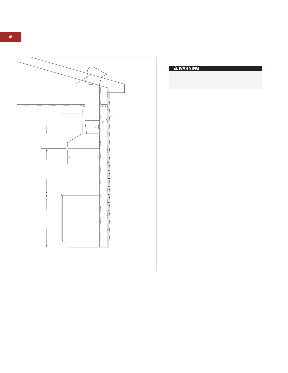
DUCTWORK INSTALLATION
THROUGH ROOF
22" (559)
DEPTH OF HOOD
10" (254) ROUND DUCT
SOFFIT OR CABINET
OR DUCT COVER
VERTICAL DISCHARGE
17
3
/4"W x 41/4"D TO 10" ROUND
9
3
/8"H (INCLUDING FLANGES)
ACCESSORY TRANSITION
FOR IN-LINE OR
REMOTE BLOWER
30" TO 36"
(762–914)
COUNTERTOP
TO BOTTOM OF
VENTILATION HOOD
36" (914)
STANDARD
FLOOR TO
COUNTERTOP
HEIGHT
10" (254)
HEIGHT OF HOOD
WALL HOOD
ROOF CAP OR REMOTE BLOWER
NOTE: 10" (254) ROUND ACCESSORY TRANSITION SHOWN IN VERTICAL DISCHARGE APPLICATION WITH
IN-LINE OR REMOTE BLOWER. REFER TO INSTALLATION INSTRUCTIONS FOR HORIZONTAL DISHCARGE.
Ducting for low-profile wall hoods with in-line or remote blower
LOW-PROFILE WALL HOODS
STEP 1: INSTALL DUCTWORK
IMPORTANT NOTE:
Wolf recommends that
the Pro low-profile wall hood be installed
30" (762) to 36" (914) above the countertop.
IMPORTANT NOTE:
Consult a qualified HVAC
Engineer for specific ducting applications.
IMPORTANT NOTE:
All Pro low-profile wall
hoods must exhaust to the outdoors except
when used with the accessory recirculating kit
(Models PW302210 and PW362210 only).
Always use metal ducting. Do not use flex
ducting.
Decide where the ductwork will run between
the wall hood and the outside. A straight, short
duct run will allow the hood to perform more
efficiently. Limit the number of elbows and
transitions to as few as possible. Long duct
runs, elbows and transitions will reduce the
performance of the hood. Wolf recommends
the maximum linear duct run be no greater
than 50' (15 m).
IMPORTANT NOTE:
There is a possibility of
noise issues, if there is a short duct run
coupled with a remote blower.
IMPORTANT NOTE:
Pro low-profile wall
hoods come standard from the factory with
horizontal or vertical discharge. When using an
in-line or external blower, use either the
optional accessory 10" (254) round transition
(part #811194) or a custom piece. The rectangular cut-out on the hood is 3
1
/4" (83) x 14"
(356).
IMPORTANT NOTE:
Internal blower
WBLOWER-50INT comes with a transition for
use with 3
1
/4" (83) x 10" (254) ducting, attached
to the blower. A 3
1
/4" (83) x 10" (254) to 8" (203)
round transition (part #804707) for use with
WBLOWER-50INT is available as a sales
accessory.
To reduce the risk of fire, use only metal
ductwork.
Page 11
11
Dimensions in parentheses are in
millimeters unless otherwise specified.
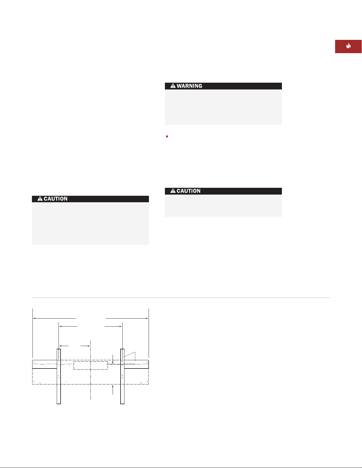
STEP 2: WALL PREPARATION
Construct the wall framing as shown in the
illustration below. Be sure to locate horizontal framing using the desired installation
height of the hood.
Refer to the illustrations below for the location
of mounting holes for low-profile wall hoods.
LOW-PROFILE WALL HOODS
STEP 1: INSTALL DUCTWORK
Always install a roof or wall cap if you are not
installing a remote blower. Connect 8" (203) or
10" (254) round metal ductwork to the cap and
work back towards the hood. Use duct sealing
tape on joints between ductwork sections.
Local codes may require the use of a backdraft
damper. Contact your local HVAC professional
for specific requirements. In cold weather
installations, a backdraft damper is necessary
to minimize the backflow of cold air into the
room.
Local building codes may require the use of
make-up air. Consult your local HVAC professional for specific requirements in your area.
Framing must be tied together and to
ceiling joists to provide enough structural
strength to support the weight of the hood
and internal blower, if applicable.
If wall framing is not available, wall
anchors must be used.
Wall framing
To reduce the risk of fire and electric
shock, install this ventilation hood only
with a blower manufactured by Wolf.
Blower model numbers are listed on
page 24.
INSTALLATION INSTRUCTIONS
STEP 3: HOOD PREPARATION
IMPORTANT NOTE:
If an optional duct cover
is to be used, follow the instructions on page
18 before installing the wall hood. If you are
installing a recirculating kit, refer to instructions included with the kit before installing the
wall hood.
WIDTH OF HOOD
1
26
" (667) TO
/4
FRAMING STUD CENTERS
1
13
"
/8
(333)
1
8
"
/4
(210) TO
CENTER
OF STUD
HOOD CENTERLINE
FRAMING
STUDS
Page 12
12
WOLF PRO WALL VENTILATION HOODS
LOW-PROFILE WALL HOODS
If you are using WBLOWER-50INT, refer to
installation instructions provided with the
blower and follow instructions for horizontal
and vertical discharge. Install the blower in
the hood before mounting the hood to the
wall.
Remove the filters by pushing each filter up
at the angle it is placed in, and rotate down.
Remove the center filter first. Gloves should
be worn to provide the proper grip when
removing filters.
If you are using an inline or remote blower,
attach the optional accessory 10" (254)
round transition or custom piece to the top
of the wall hood using holes provided.
If you are installing an in-line or remote
blower, drill a
7
/8" (22) hole through the
wood framing for the conduit. Refer to the
in-line and remote blower information on
pages 22–23 and follow installation instructions provided with the blower.
IMPORTANT NOTE:
Do not run wiring for the
remote blower through the ductwork.
STEP 4: HOOD INSTALLATION
IMPORTANT NOTE:
If a backsplash is to be
used, it should be installed before the wall
hood is mounted. Refer to the instructions
included with the kit for complete mounting
instructions.
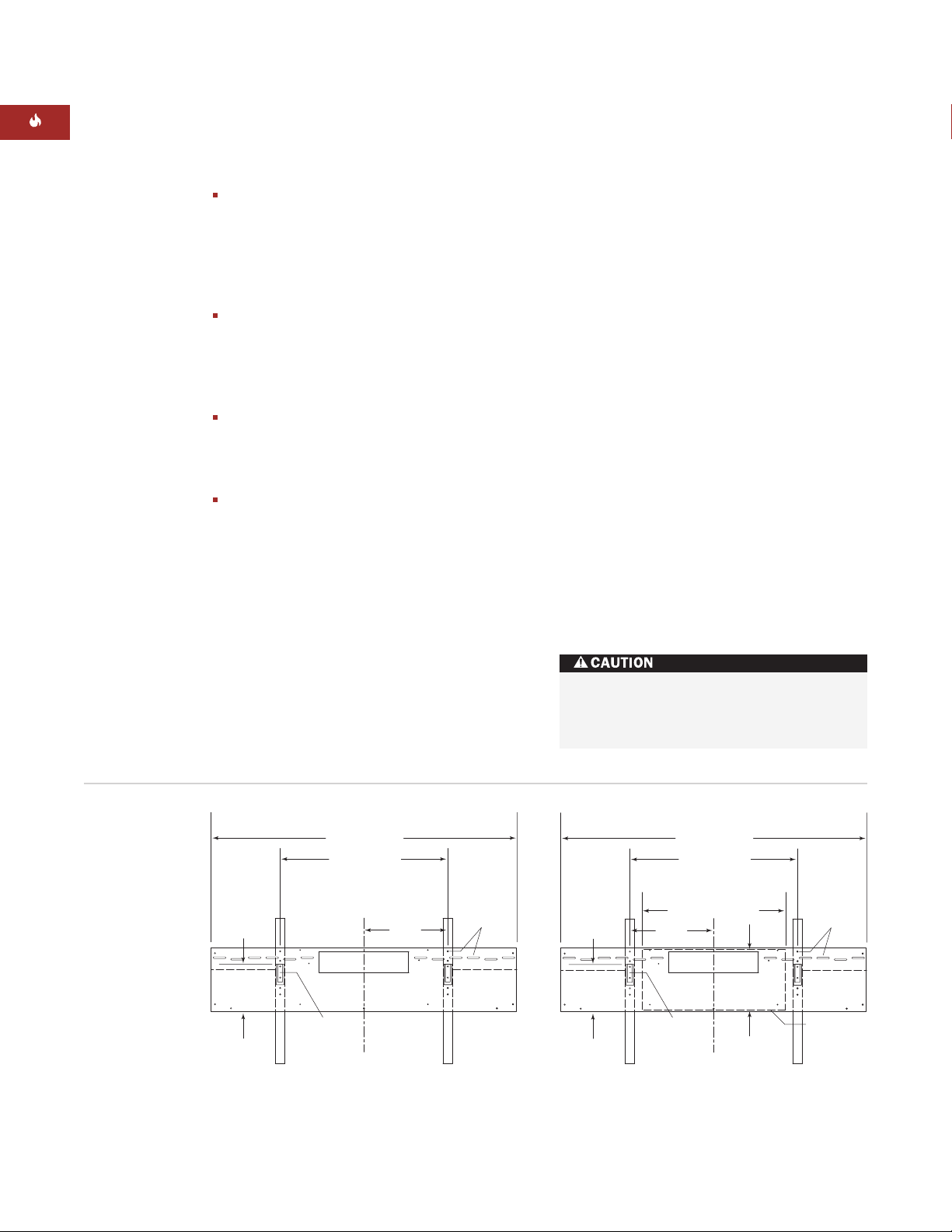
Install the wall mounting brackets as shown in
the illustration below. Hang the wall hood on
the installation brackets in preparation for
attaching the hood to framing.
Position the hood in the desired location on
the wall. Depending on the application, install
the #10 x 1
1
/2" (38) screws with washers or
3" (76) drywall screws through the mounting
holes on the back plate. Verify that the screws
engage the wall studs or framing. If not, wall
anchors must be used.
IMPORTANT NOTE:
If additional support is
required for the wall hood, drill supplementary
mounting holes in the back plate and use these
holes to attach the hood assembly to the wall
framing.
Due to the weight of the wall hood, be
sure to have adequate manpower for
installation.
WIDTH OF HOOD
26
1
/4
" (667) TO
MOUNTING BRACKET
HOLE CENTERS
13
1
/8
"
(333)
HOOD CENTERLINE
USE ROUND
AND SLOTTED
HOLES TO
SECURE HOOD
TO WALL
STUDS
MOUNT
BRACKETS TO
WALL FRAMING
7
7
/16
" (189)
TO TOP OF
BRACKET
Hood installation—vertical discharge
WIDTH OF HOOD
26
1
/4
" (667) TO
MOUNTING BRACKET
HOLE CENTERS
22
1
/2
" (572)
CENTERED ON HOOD
9
1
/2
" (229)
CENTERED
ON HOOD
13
1
/8
"
(333)
HOOD CENTERLINE
USE ROUND
AND SLOTTED
HOLES TO
SECURE HOOD
TO WALL
STUDS
MOUNT
BRACKETS TO
WALL FRAMING
7
7
/16
" (189)
TO TOP OF
BRACKET
WALL HOLE
CUT-OUT
Hood installation—horizontal discharge
Page 13
13
Dimensions in parentheses are in
millimeters unless otherwise specified.
INSTALLATION INSTRUCTIONS
24" (610) AND 27" (686) WALL HOODS
STEP 1: INSTALL DUCTWORK
IMPORTANT NOTE:
Wolf recommends that
the Pro wall ventilation hood be installed
30" (762) to 36" (914) above the countertop.
IMPORTANT NOTE:
Consult a qualified HVAC
Engineer for specific ducting applications.
IMPORTANT NOTE:
All Pro 24" (610) and 27"
(686) deep wall hoods must exhaust to the
outdoors except when used with the accessory
recirculating kit (Models PW302418 and
PW362418 only). Always use metal ducting. Do
not use flex ducting.
Decide where the ductwork will run between
the wall hood and the outside. A straight, short
duct run will allow the hood to perform more
efficiently. Limit the number of elbows and
transitions to as few as possible. Long duct
runs, elbows and transitions will reduce the
performance of the hood. Wolf recommends
the maximum linear duct run be no greater
than 50' (15 m).
IMPORTANT NOTE:
There is a possibility of
noise issues, if there is a short duct run
coupled with a remote blower.
IMPORTANT NOTE:
If a horizontal discharge
is needed for installation of a 24" (610) or 27"
(686) deep wall hood, an accessory horizontal
discharge kit is required. Refer to instructions
included with the kit for complete mounting
and blower options. Accessory kits are available through your Wolf dealer.
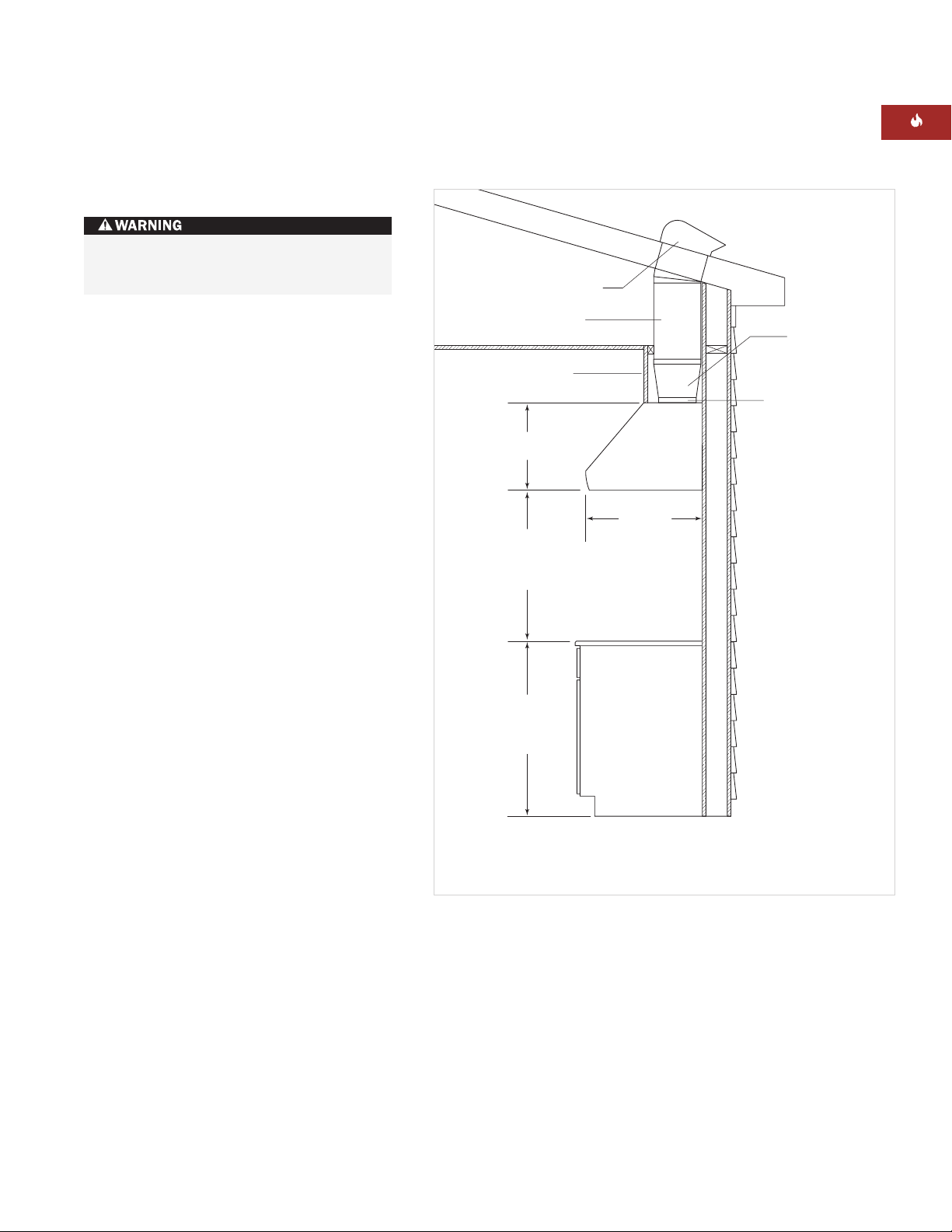
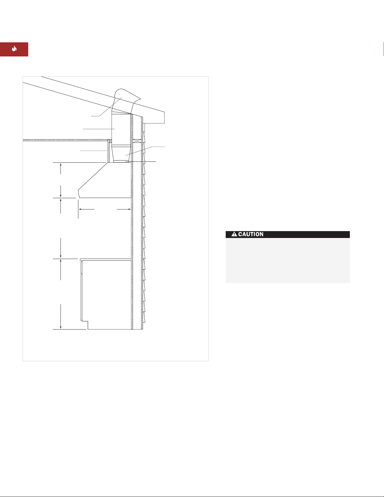
DUCTWORK INSTALLATION
THROUGH ROOF
24" (610)
DEPTH OF HOOD
ROOF CAP OR REMOTE BLOWER
10" (254) ROUND DUCT
SOFFIT OR CABINET
OR DUCT COVER
NOTE: HORIZONTAL DISCHARGE REQUIRES AN ACCESSORY KIT.
VERTICAL DISCHARGE
TRANSITION
22
1
/4"W x 9"D TO 10" ROUND
10"H (INCLUDING FLANGES)
30" TO 36"
(762–914)
COUNTERTOP
TO BOTTOM OF
VENTILATION HOOD
36" (914)
STANDARD
FLOOR TO
COUNTERTOP
HEIGHT
18" (457)
HEIGHT OF HOOD
WALL HOOD
Ducting for 24" (610) deep wall hoods
To reduce the risk of fire, use only metal
ductwork.
Page 14
14
WOLF PRO WALL VENTILATION HOODS
30" TO 36"
(762–914)
COUNTERTOP
TO BOTTOM OF
VENTILATION HOOD
18" (457)
HEIGHT OF HOOD
WALL HOOD
DUCTWORK INSTALLATION
THROUGH ROOF
36" (914)
STANDARD
FLOOR TO
COUNTERTOP
HEIGHT
27" (686)
DEPTH OF HOOD
10" (254) ROUND DUCT
SOFFIT OR CABINET
OR DUCT COVER
NOTE: HORIZONTAL DISCHARGE REQUIRES AN ACCESSORY KIT.
TRANSITION
22
1
/4"W x 9"D TO 10" ROUND
10"H (INCLUDING FLANGES)
ROOF CAP OR REMOTE BLOWER
VERTICAL DISCHARGE
Ducting for 27" (686) deep wall hoods
24" (610) AND 27" (686) WALL HOODS
STEP 1: INSTALL DUCTWORK
Always install a roof or wall cap if you are not
installing a remote blower. Connect 10" (254)
round metal ductwork to the cap and work
back towards the hood. Use duct sealing tape
on joints between ductwork sections.
Wolf Pro 24" (610) and 27" (686) deep wall
hoods come standard with a backdraft damper
included in the transition assembly. Local
codes may require the use of an additional
backdraft damper. Contact your local HVAC
professional for specific requirements. In cold
weather installations, a backdraft damper is
necessary to minimize the backflow of cold air
into the room.
Local building codes may require the use of
make-up air. Consult your local HVAC professional for specific requirements in your area.
To reduce the risk of fire and electric
shock, install this ventilation hood only
with a blower manufactured by Wolf.
Blower model numbers are listed on
page 24.
Page 15
IMPORTANT NOTE:
The screws should be
countersunk so that they are below flush.
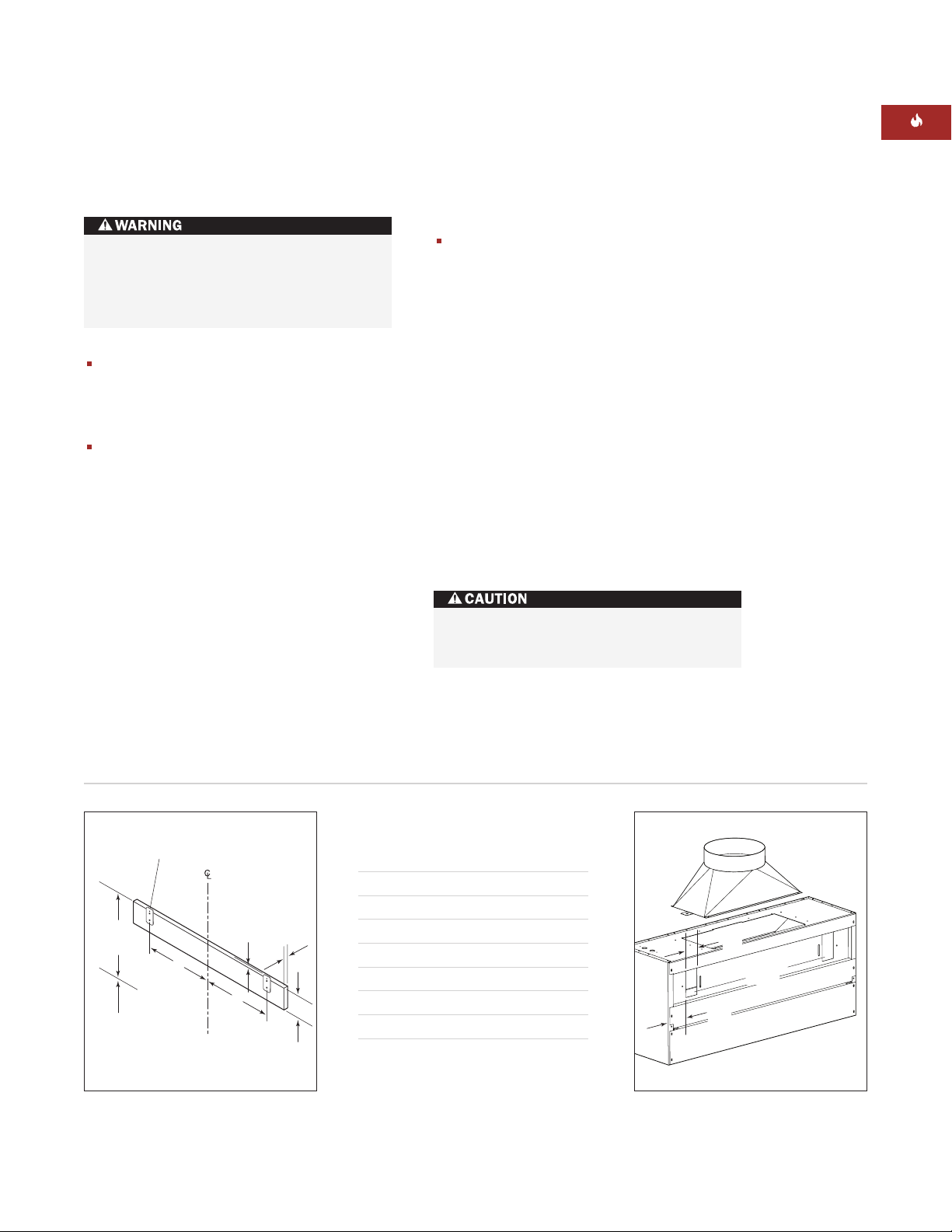
Install the flat metal hood retaining brackets
to the wood mounting support at the locations shown in the illustration and the chart
below. Use the provided #10 X 1
1
/2" (38)
screws and washers to secure these
brackets in place. The metal bracket should
be mounted
1
/2" (13) above the top of the
wood mounting support.
IMPORTANT NOTE:
The location of this wood
mounting support and retaining bracket allow
for
1
/2" (13) clearance at the top of the hood for
ease of installation. This gap will be taken up
during final mounting of the hood to the wood
mounting support.
Refer to the illustration below for the location
of mounting holes for the Pro 24" (610) and 27"
(686) deep wall hoods.
15
Dimensions in parentheses are in
millimeters unless otherwise specified.
INSTALLATION INSTRUCTIONS
ACCESSORIES
Optional accessories are available
through your
Wolf dealer. To
obtain local dealer
information, visit
the Showroom
Locator section of
our website,
wolfappliance.com.
If wall framing is not available, wall
anchors must be used.
4
7
/16
"
(113)
2
1
/2
"
(64)
MOUNTING
HOLES
Location of mounting holes
24" (610) AND 27" (686) WALL HOODS
STEP 2: WALL PREPARATION
Construct the wood wall framing flush with
the wall studs and centered in the location
that the hood will be mounted. Finish the
wall surface.
Attach the provided wood mounting
support. Refer to the illustration and the
chart below. The wood support should be
centered within the desired hood location.
Use the provided 3" (76) screws to attach
the support to the wall. The location of
these screws should correspond to the
wood supports within the walls or the
framing.
Framing must be tied together to provide
enough structural strength to support the
weight of the hood and internal blower, if
applicable.
Wood mounting support
Wood Mounting Support
Hood Width (A) (B)
30" (762) 113/4" (298) 151/8" (384)
36" (914) 121/4" (311) 151/8" (384)
42" (1067) 151/4" (387) 151/8" (384)
48" (1219) 181/4" (464) 151/8" (384)
54" (1372) 211/4" (540) 151/8" (384)
60" (1524) 241/4" (616) 151/8" (384)
66" (1676) 271/4" (692) 151/8" (384)
HOOD RETAINING
BRACKET
B
TO BOTTOM
OF HOOD
A
30" TO 36"
(762–914)
BOTTOM OF
HOOD TO
COUNTERTOP
CENTER LINE
OF HOOD
LOCATION
1
/2" (13)
A
3
" (19)
/4
3
(92)
5
"
/8
Page 16
16
WOLF PRO WALL VENTILATION HOODS
24" (610) AND 27" (686) WALL HOODS
STEP 3: HOOD PREPARATION
IMPORTANT NOTE:
If a duct cover is to be
used, follow instructions on page 18 before
installing the wall hood. If you are installing a
recirculating kit, refer to instructions included
with the kit before installing the wall hood.
IMPORTANT NOTE:
Wolf recommends
installing the internal blower to the back plate
prior to mounting the hood.
If you are installing WBLOWER-60INT,
WBLOWER-90INT or WBLOWER-120INT,
refer to the internal blower information on
page 21 and follow installation instructions
provided with the blower assembly.
The hood assembly is shipped with the
back plate/transition attached. The
transition is shipped upside down in the top
of the hood. It must be removed and reinstalled in the proper position.
Remove the filters by pushing each filter up
at the angle it is placed in, and rotate down.
Remove the center filter first. Then take out
the grease cups placed on the bottom edge
of the hood coinciding with the bottom
edge of the filters. Gloves should be worn
to provide the proper grip when removing
filters.
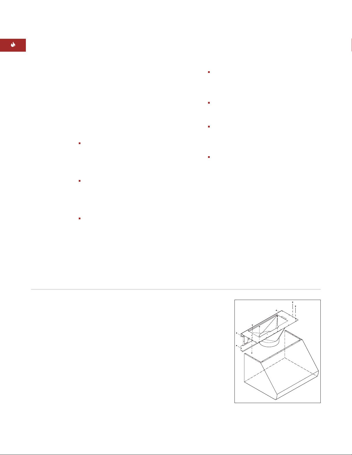
Detach the back plate/transition assembly
from the hood by removing the screws
from the top and back of the assembly.
Refer to the illustration below.
Separate the transition from the back plate
by removing the shipping nut from the
inside of the back plate.
Position the back plate in the desired
location and mark the mounting holes on
the wood support. Drill pilot holes for the
mounting hardware.
If you are installing an in-line or remote
blower, drill an additional
7
/8" (22) hole
through the wood framing for the conduit
in order to run power to the blower. Refer
to the illustration on page 19 for location of
the electrical box and to the in-line and
remote blower information on pages 22–23.
Also, follow installation instructions
provided with the blower assembly.
IMPORTANT NOTE:
Do not run wiring for the
remote blower through the ductwork.
Back plate/transition assembly
Page 17
17
Dimensions in parentheses are in
millimeters unless otherwise specified.
INSTALLATION INSTRUCTIONS
24" (610) AND 27" (686) WALL HOODS
STEP 4: REATTACH BACK PLATE
Follow these instructions to reattach the back
plate to the wall hood:
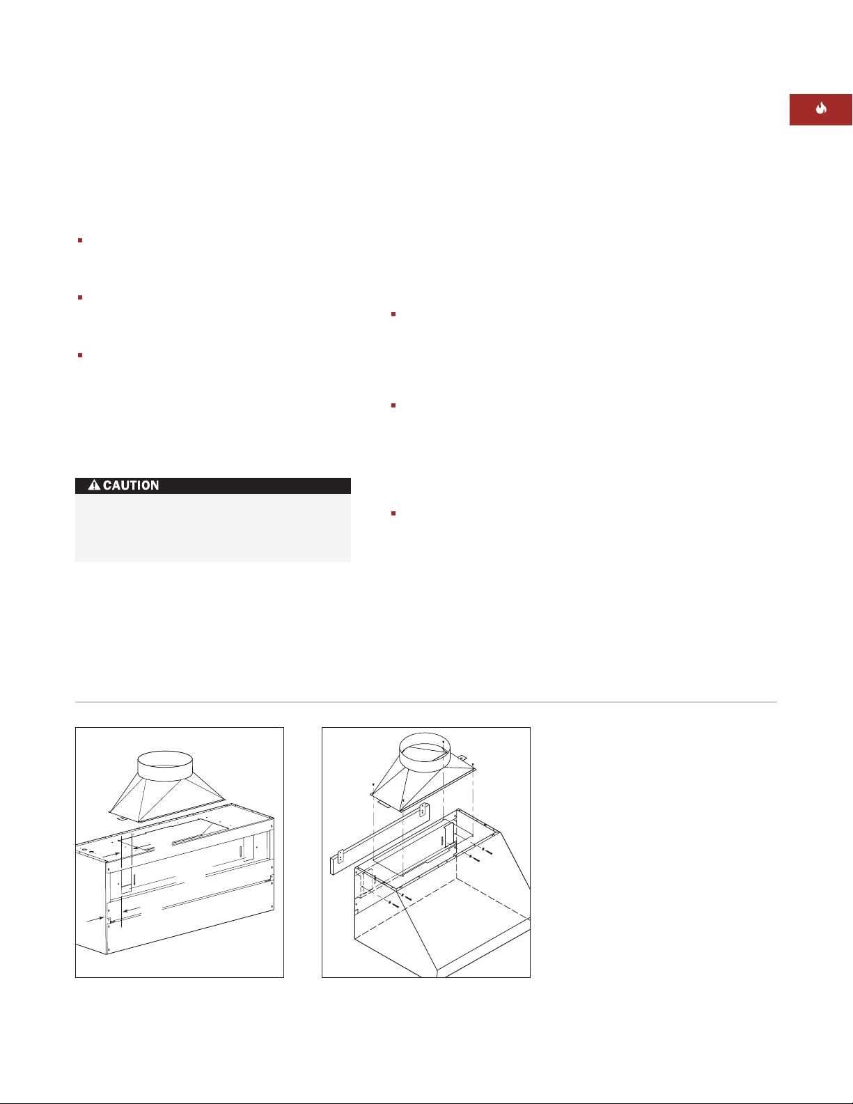
Attach the transition to the back plate using
the four shipping screws provided in the
hardware mounting kit.
Reinstall the shipping screws removed
previously from the top and back of the
back plate.
Use duct sealing tape to ensure a tight seal
from the transition to the back plate.
IMPORTANT NOTE:
If additional support is
required, drill supplementary mounting holes
in the back plate and use these holes to attach
the hood assembly to the wall framing.
Due to the weight of the hood, be
sure to have adequate manpower for
installation.
STEP 5: HOOD INSTALLATION
IMPORTANT NOTE:
If a backsplash is to be
used, it should be installed before the wall
hood is mounted. Refer to instructions
included with the backsplash.
Follow these instructions to install the wall
hood:
Align the mounting holes in the back plate
of the hood assembly with the metal
retaining brackets on the wood mounting
support. Refer to the illustration below for
location of the mounting holes.
Position the hood and install the #10 x 1
1
/2"
(38) screws and washers (included in the
hardware mounting kit) through the
mounting holes on the back plate. Refer to
the illustration below. Verify that the screws
engage the wood mounting support.
Attach the transition to existing ductwork
with sheet metal screws and duct sealing
tape.
Location of mounting holes Hood installation
1
2
"
/2
(64)
MOUNTING
HOLES
7
4
"
/16
(113)
Page 18
18
WOLF PRO WALL VENTILATION HOODS
ACCESSORIES
Optional accessories are available
through your
Wolf dealer. To
obtain local dealer
information, visit
the Showroom
Locator section of
our website,
wolfappliance.com.
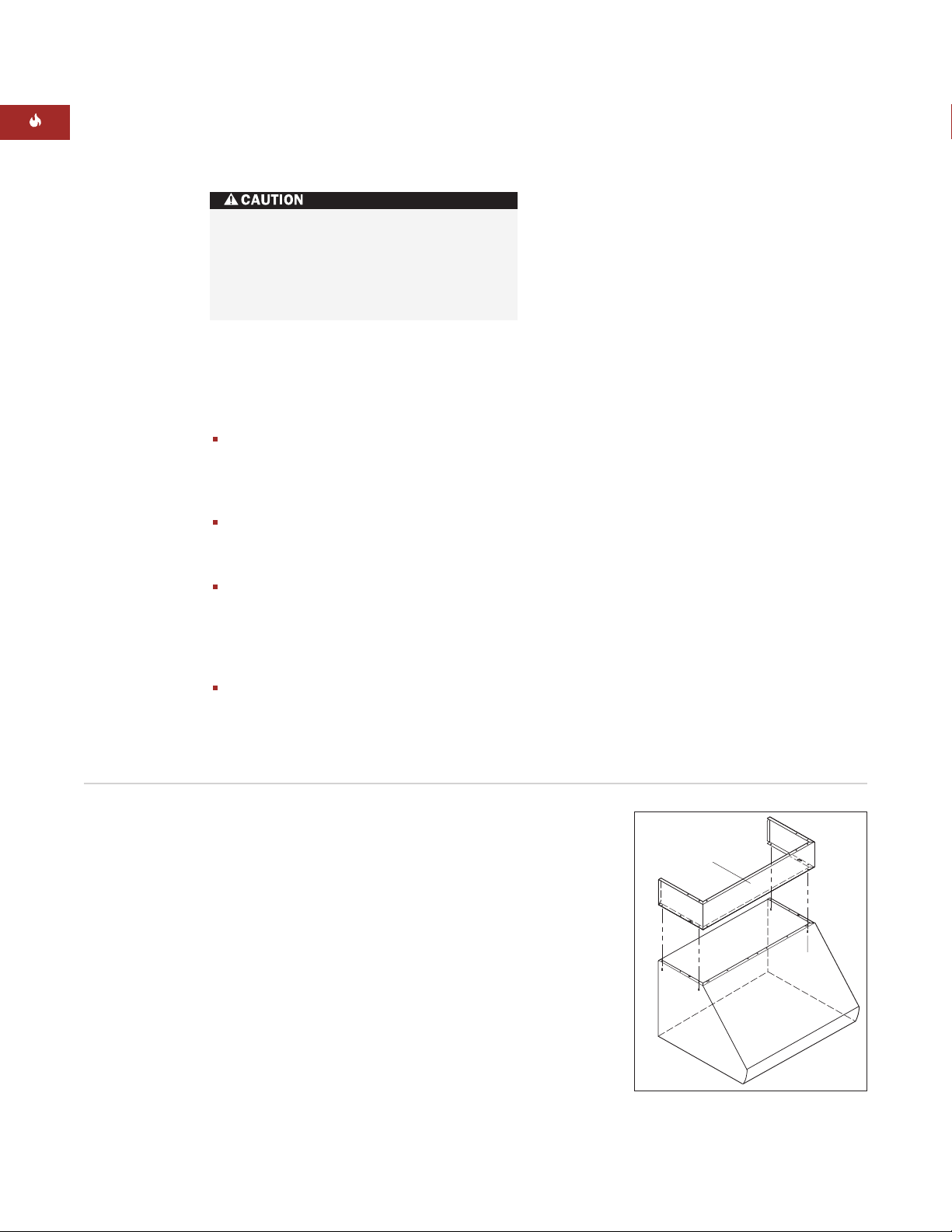
DUCT COVER INSTALLATION
Duct cover installation
Installing a duct cover assembly will
impact all aspects of the hood installation including hood location, ducting,
electrical placement and the mounting
surface.
Duct covers 6" (152), 12" (305), 18" (457) and
24" (610) high in widths to match all wall
hoods are available through your Wolf
dealer. To obtain local dealer information,
visit the Showroom Locator section of our
website, wolfappliance.com.
IMPORTANT NOTE:
If an optional duct cover
is to be used with any Wolf Pro wall hood,
follow these instructions before installing the
hood:
Remove all screws from the front edge of
the back panel on the top of the wall hood.
Leave the two screws on the sides as there
is a relief in the duct cover for them.
Attach the duct cover from the inside of the
hood through the filter opening using the
screws provided.
Leave screws partially loose until all screws
are installed. Check alignment of the duct
cover with the hood and tighten the four
corner screws to secure the duct cover.
Tighten all remaining screws.
Continue with the installation of the wall
hood.
Optional
Duct Cover
Mounting
Screws
Page 19
19
Dimensions in parentheses are in
millimeters unless otherwise specified.
INSTALLATION INSTRUCTIONS
Do not remove the control knob bezel to
access hood wiring; this will damage the
bezel assembly.
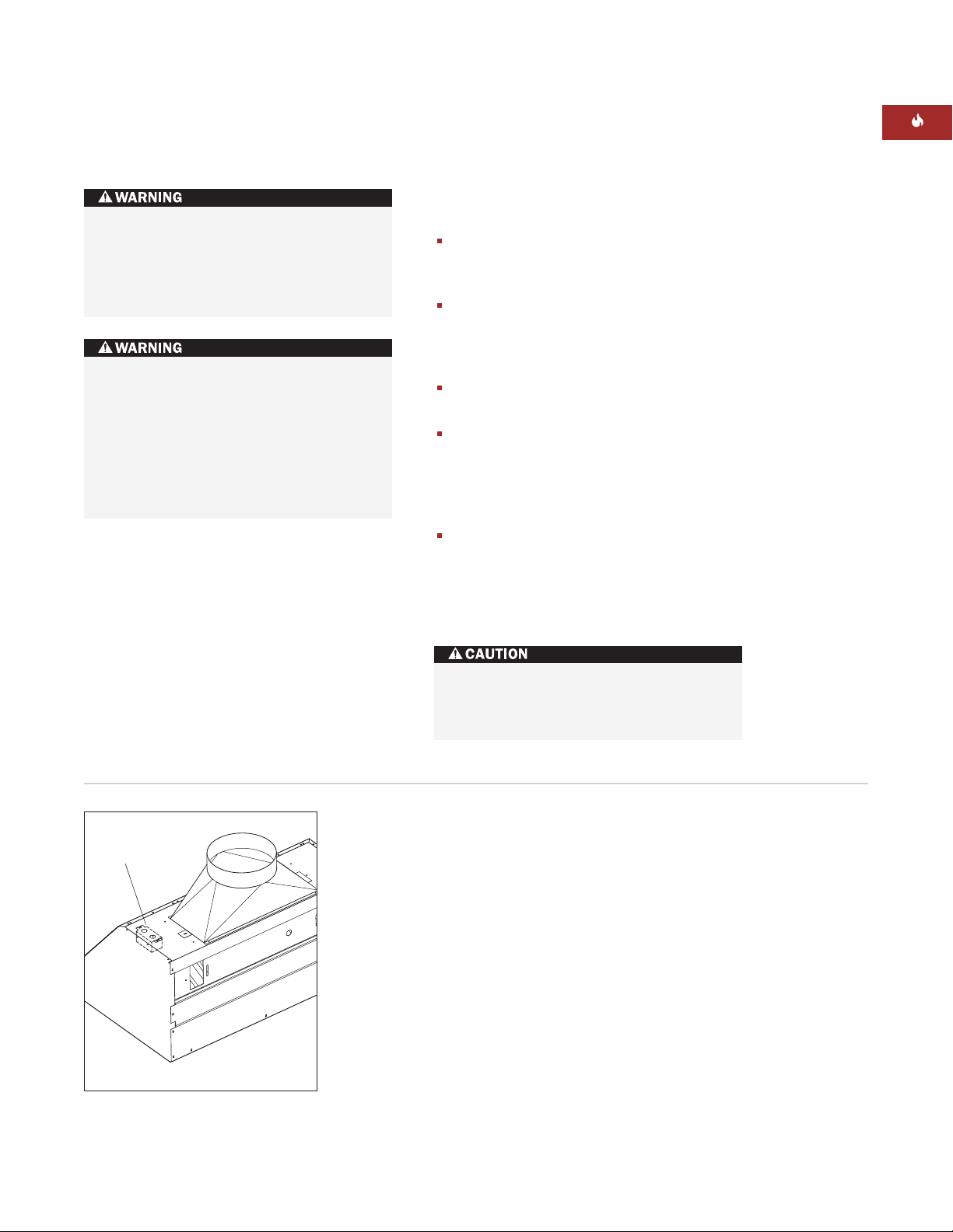
Location of electrical box
IMPORTANT
NOTE
You must follow
all National
Electrical Code
regulations. In
addition, be aware
of local codes and
ordinances when
installing your
service.
ELECTRICAL WIRING
This ventilation hood must be properly
grounded. This unit should be installed by
a qualified electrician in accordance with
all applicable national and local electrical
codes.
Before servicing or cleaning unit, switch
power off at service panel and lock the
service disconnecting means to prevent
power from being switched on accidentally. When the service disconnecting
means cannot be locked, securely fasten a
prominent warning device, such as a tag,
to the service panel.
Follow these instructions to install wiring for
all Wolf Pro wall hoods:
Run a 120 V AC, 15 amp circuit power cable
from the service panel to the electrical box
on the back plate.
Run the conduit connector through the
holes in the back plate. Refer to the illustration below for the location of the electrical
box.
Insert the conduit through the hole on top
of the back plate to the electrical box.
Remove the electrical box cover from the
back plate. Connect black wire to power
supply black wire, white wire to power
supply white wire and green wire to green
wire or bare wire.
Place all wiring connections inside the
electrical box and reinstall on the back plate
in the upper right-hand corner. Make sure
that the wires are secure and that no wires
are pinched between the cover and box.
Electrical
Box
Page 20
20
WOLF PRO WALL VENTILATION HOODS
ACCESSORIES
Optional accessories are available
through your
Wolf dealer. To
obtain local dealer
information, visit
the Showroom
Locator section of
our website,
wolfappliance.com.
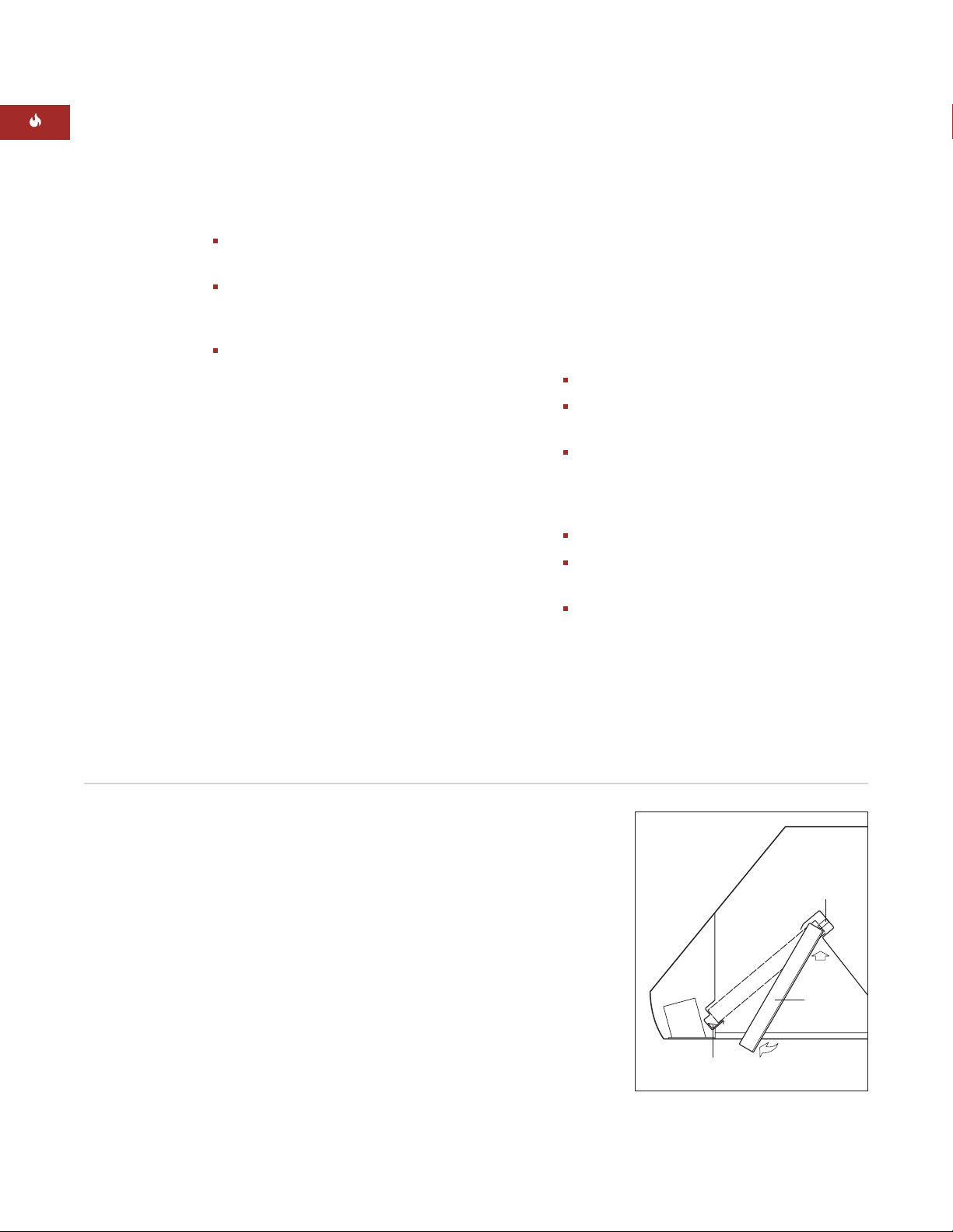
FILTER INSTALLATION
Follow these instructions to install filters and
grease cups for Wolf Pro wall hoods:
Remove all packaging material from the
filters and grease cups.
Slide the grease cups along the bottom
edge of the hood so that the lip of the
grease cup overhangs slightly.
Install the filters. Orient each filter with
lines running vertically. Position the top
edge of the filter as shown in the illustration below. While pressing up against the
spring, rotate the bottom edge of the filter
into position next to the grease cup. Gloves
should be worn to provide proper grip
when installing filters.
IMPORTANT NOTE:
The illustration shows a
27" (686) deep wall hood filter installation, with
the filter sloping up from front to back. For
low-profile and 24" (610) deep hoods, the filter
will slope down from front to back.
WOLF NAMEPLATE
The Wolf logo nameplate does not come
installed on the hood since there are various
locations that the nameplate can be attached.
Also, some customers prefer not to have a
nameplate on their hood.
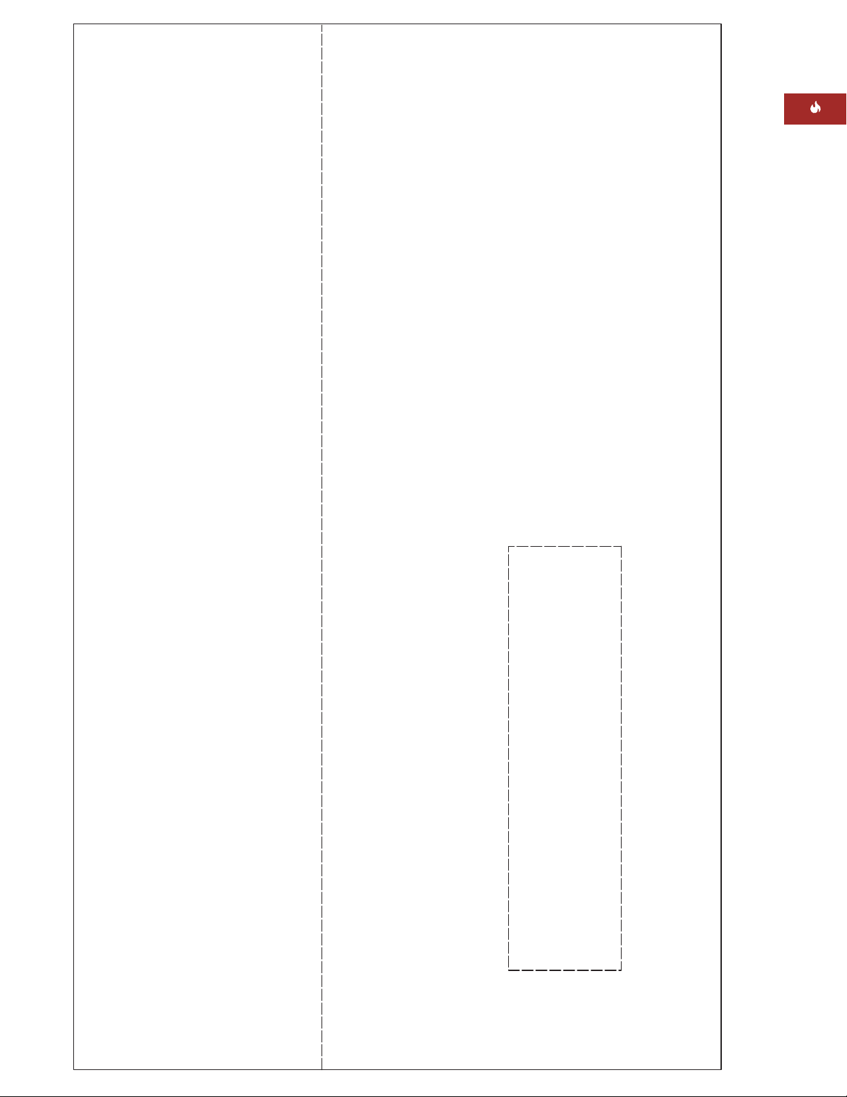
A template for positioning the Wolf logo
nameplate in a standard location is included
on the back page. Follow these steps to install
the nameplate:
Decide on the location for the nameplate.
Clean the mounting area with rubbing
alcohol.
If desired, cut out the template from the
back page. Fold the template, locate placement on hood and tape to the hood surface.
Check alignment and adjust if necessary.
Remove backing paper from the nameplate.
Position the nameplate in the template
cut-out and press into place.
Remove the template and any tape residue.
Filter installation—27" (686) deep
wall hood shown
Spring
Filter
Grease Cup SIDE VIEW
Page 21
21
Dimensions in parentheses are in
millimeters unless otherwise specified.
INSTALLATION INSTRUCTIONS
INTERNAL BLOWERS
BLOWER INSTALLATION
IMPORTANT NOTE:
Refer to the specific
installation instructions provided with each
internal blower for additional mounting and
wiring instructions.
IMPORTANT NOTE:
Use wire connectors or
wire nuts approved by UL or C/UL.
IMPORTANT NOTE:
Wolf recommends
installing the internal blower to the back plate
assembly prior to installing the hood to the
wall framing.
IMPORTANT NOTE:
For low-profile wall
hoods using the 500 CFM internal blower, refer
to the WBLOWER-50INT installation instructions for details.
24" (610) AND 27" (686) DEEP HOODS
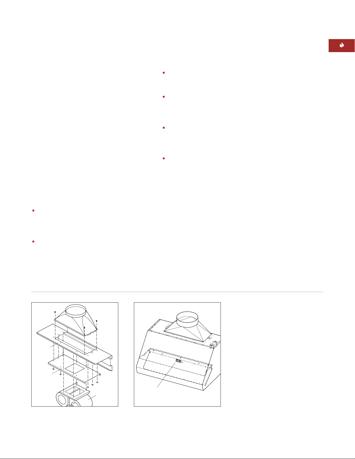
Assemble the blower housing to the blower
mounting plate. Follow installation instructions included with the blower assembly for
proper installation.
Attach the blower assembly to the hood
mounting plate. To attach, slide the blower
mounting plate over the weld studs and
secure with eight nuts (included with the
blower). Refer to the illustration below.
Verify that the blower discharge aligns with
the discharge cut-out in the back panel of
the hood.
Install the hood and blower assembly to the
wall. Secure the power cord(s) without
damaging or pinching while installing the
hood.
Follow hood installation instructions beginning on page 9 for low-profile wall hoods,
and page 12 for 24" (610) and 27" (686)
deep wall hoods.
Once the hood installation is complete, plug
the blower power cord(s) into receptacle(s)
located near the center of the hood shell.
Refer to the illustration below. Use the clips
on the interior of the hood to keep excess
power cord away from moving parts.
IMPORTANT NOTE:
Before turning the power
on to the ventilation hood, make sure the
blower is off.
Internal blower installation
Blower
Receptacle(s)
Blower receptacle location
Hood
Back
Plate
Blower
Mounting
Plate
Blower
Housing
Page 22
22
WOLF PRO WALL VENTILATION HOODS
ACCESSORIES
Optional accessories are available
through your
Wolf dealer. To
obtain local dealer
information, visit
the Showroom
Locator section of
our website,
wolfappliance.com.
IN-LINE AND REMOTE BLOWERS
BLOWER INSTALLATION
IMPORTANT NOTE:
Refer to the specific
installation instructions provided with each
blower for additional mounting instructions.
Locate the blower so that the length of the
duct run and number of elbows and transitions
are kept to a minimum. Wolf recommends the
maximum linear duct run be no greater than
50' (15 m).
If possible, remote blowers should be located
between wall studs or roof rafters. Avoid
pipes, wires or other ductwork that may be
running through the wall.
Be sure that there is enough space for any
transitions that may be needed between the
blower and the connecting ductwork. For best
performance, locate transitions nearest the
blower.
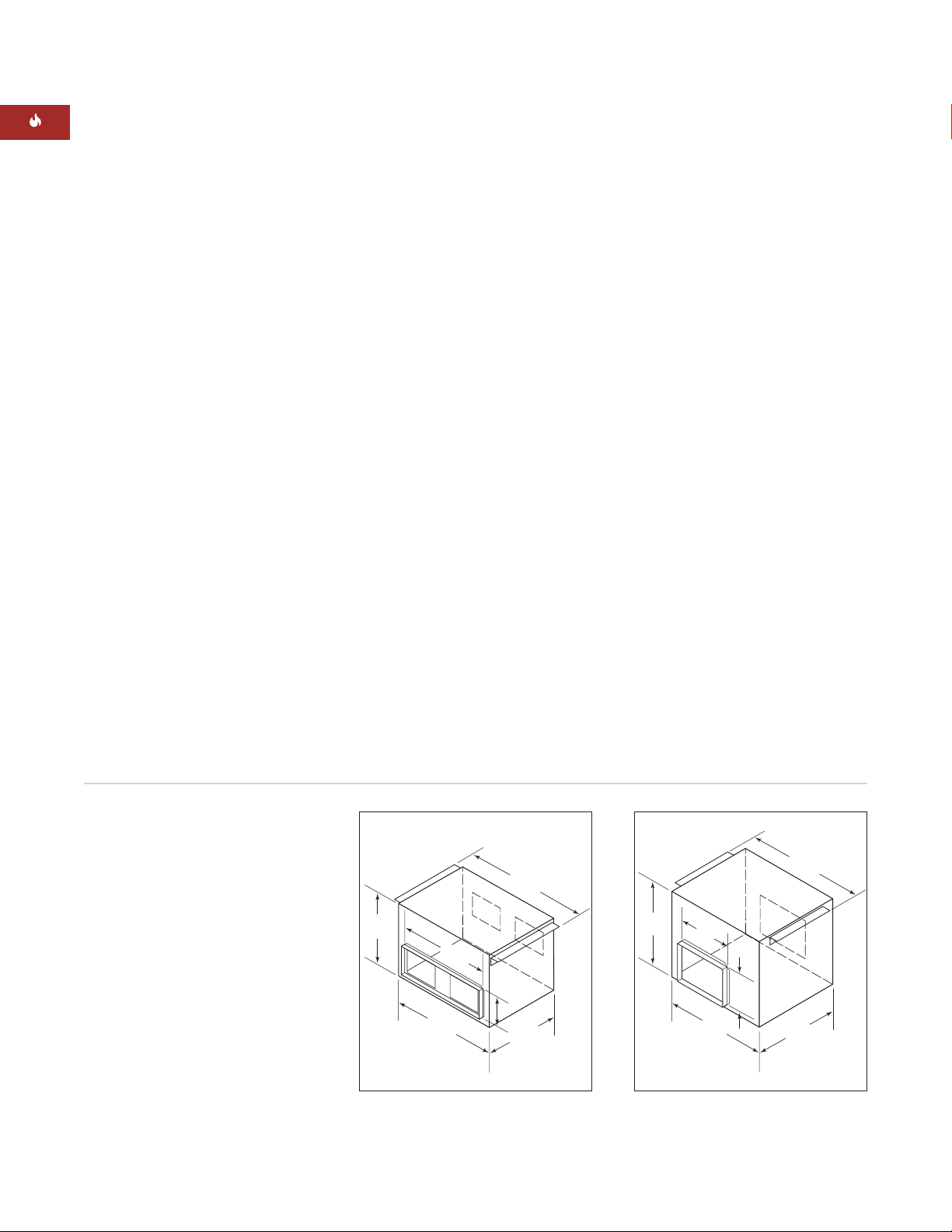
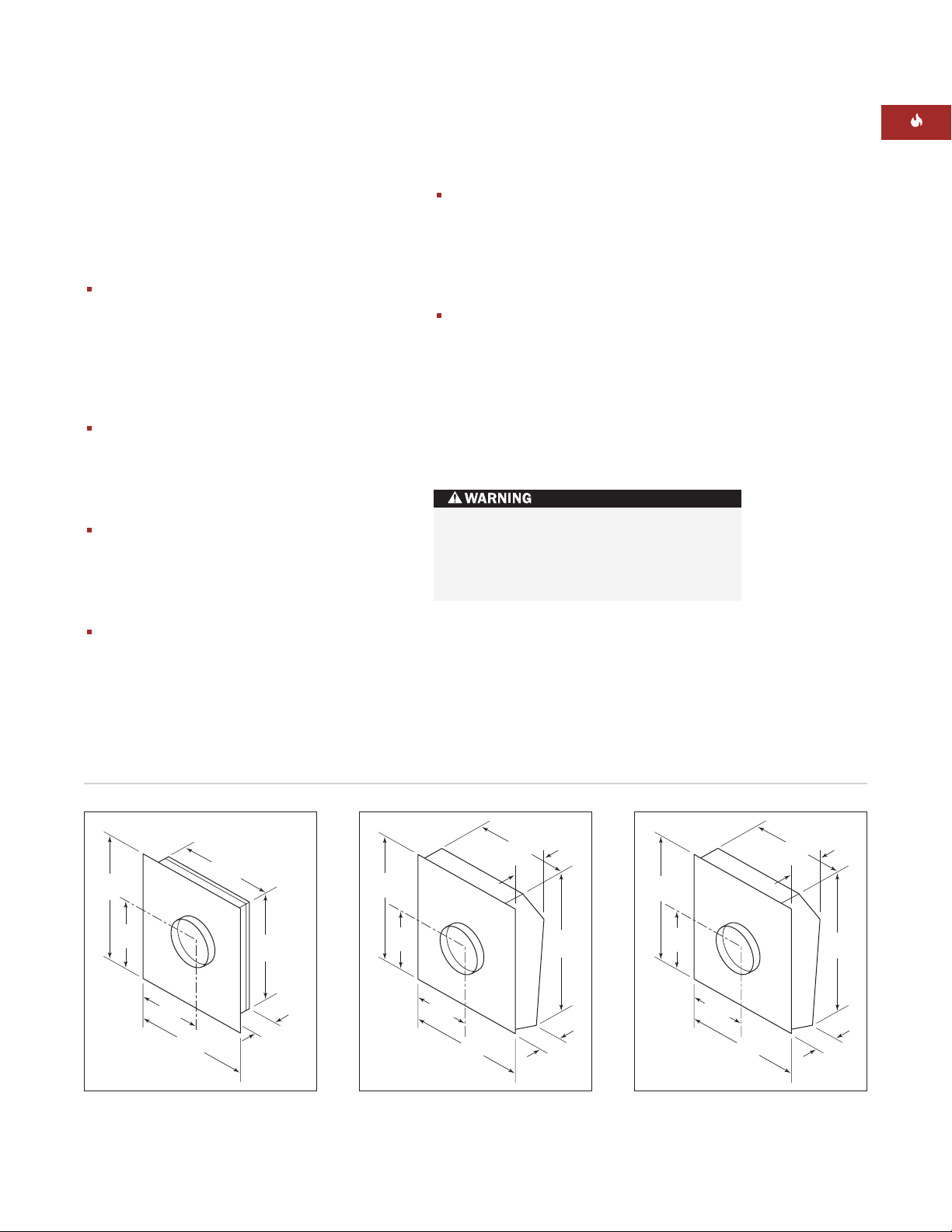
Refer to the illustrations below and on the
following page for overall dimensions of Wolf
in-line and remote blowers. Also refer to the
specific installation instructions provided with
each remote blower to verify cut-out dimensions.
Dimensions for BLOWER-60IL
Dimensions for BLOWER-110IL
243/8"
(619)
113/4"
(298)
181/2"
(470)
41/2"
(114)
211/2"
(546)
121/4"
(311)
7
24
/8
(632)
18"
(457)
12"
(305)
22"
(559)
8"
(203)
18"
(457)
"
Page 23
23
Dimensions in parentheses are in
millimeters unless otherwise specified.
INSTALLATION INSTRUCTIONS
IN-LINE AND REMOTE BLOWERS
BLOWER WIRING
IMPORTANT NOTE:
Refer to the specific
installation instructions provided with each
blower for additional wiring instructions.
Follow wiring instructions at the blower as
outlined in the specific installation instructions provided with each blower. Black (L1)
to black, white (neutral) to white, or white
to blue, or white to brown (depending on
model) and green to grounding screw. Run
blower cable (ROMEX) to the hood.
Insert 6" (152) of ROMEX cable through the
knockout opening and into the electrical
box on the back plate of the hood. Secure
the cable to the electrical box with an
appropriate connector.
Locate the cord assembly provided with the
blower. The cord assembly has two leads,
black (L1) and white (neutral). Connect
these leads to the leads from the blower,
black to black and white to white.
Connect
all
green and bare wires together
to the ground screw in the electrical box.
Plug the cord assembly into the receptacle
located near the center of the hood shell.
Refer to the illustration on page 21. Use the
clips on the interior of the hood to keep
excess power cord away from moving
parts.
Reinstall the electrical box cover and
screws in the upper right-hand corner of the
hood. Make sure that all wires are secure
and that no wires are pinched between the
cover and box.
IMPORTANT NOTE:
Before turning the power
on to the ventilation hood, make sure the
blower is off.
When making electrical connections,
make sure the electrical power is turned
off at the power source or circuit breaker
before proceeding.
Dimensions for BLOWER-60REM and
BLOWER-90REM
Dimensions for BLOWER-150REMDimensions for BLOWER-120REM
3
/4
20
"
28
(718)
1
/4
15
(394)
"
Diameter
1
"
/2
14"
(356)
10" (254)
3
/4
24
(629)
(527)
1
24
"
/2
(622)
3
4
"
/4
"
(121)
29
(749)
25"
(635)
21" (533)
10"
(254)
29
(749)
7
(184)
1
"
/2
1
"
/4
18" (457)
10"
1
"
/2
10" (254)
Diameter
3
14
"
/4
(375)
1
10
"
/8
(257)
22"
(559)
(254)
29
(749)
7
(184)
1
29
"
/2
(749)
1
/2
"
1
/4
"
14
(375)
10" (254)
Diameter
3
"
/4
3
10
"
/8
(264)
Page 24
24
WOLF PRO WALL VENTILATION HOODS
IN-LINE BLOWERS
BLOWER-60IL (808331) –
600 CFM
in-line blower for low-profile wall hoods
and 24" (610) and 27" (686) deep wall
hoods, Models PW302418 and PW302718.
BLOWER-110IL (808332) –
1100 CFM
in-line blower for all 24" (610) and 27" (686)
deep wall hoods.
REMOTE BLOWERS
BLOWER-60REM (801640) –
600 CFM
remote blower for low-profile wall hoods
and Models PW302418 and PW302718.
BLOWER-90REM (801641) –
900 CFM
remote blower for low-profile wall hoods
and 24" (610) and 27" (686) deep wall
hoods; 30" (762), 36" (914), 42" (1067), 48"
(1219) and 54" (1372) wide models.
BLOWER-120REM (801642) –
1200 CFM
remote blower for all 24" (610) and 27" (686)
deep wall hoods.
BLOWER-150REM (804701) –
1500 CFM
remote blower for all 24" (610) and 27" (686)
deep wall hoods.
BLOWER ASSEMBLIES
Wolf Pro wall ventilation hoods are shipped
without the blower assembly. Wolf internal,
in-line and remote blower assemblies are
available as sales accessories through your
Wolf dealer.
IMPORTANT NOTE:
Blower options vary with
the cooking surface. Use only a Wolf blower
with the Pro wall ventilation hood.
Refer to the Wolf Design Guide for Pro
ventilation recommendations. You can also
visit our website at wolfappliance.com.
INTERNAL BLOWERS
WBLOWER-50INT (810991) –
500 CFM
internal blower for all low-profile wall
hoods.
WBLOWER-60INT (810559) –
600 CFM
internal blower for 24" (610) and 27" (686)
deep wall hoods; 30" (762), 36" (914) and
42" (1067) wide models.
WBLOWER-90INT (811131) –
900 CFM
internal blower for 24" (610) and 27" (686)
deep wall hoods; 30" (762), 36" (914) and
42" (1067) wide models.
WBLOWER-120INT (810316) –
1200 CFM
internal blower for 24" (610) and 27" (686)
deep wall hoods; 48" (1219), 54" (1372), 60"
(1524) and 66" (1676) wide models.
ACCESSORIES
Optional accessories are available
through your
Wolf dealer. To
obtain local dealer
information, visit
the Showroom
Locator section of
our website,
wolfappliance.com.
Page 25

25
Dimensions in parentheses are in
millimeters unless otherwise specified.
INSTALLATION INSTRUCTIONS
ACCESSORY KITS
RECIRCULATING KITS
RECIRC30 (808223) –
Must be used with
WBLOWER-50INT (810991) for low-profile
wall hoods and WBLOWER-60INT (810559)
for 24" (610) deep wall hoods.
RECIRC36 (808224) –
Must be used with
WBLOWER-50INT (810991) for low-profile
wall hoods and WBLOWER-60INT (810559)
for 24" (610) deep wall hoods.
Page 26

26
WOLF PRO WALL VENTILATION HOODS
The information and images in this book are the
copyright property of Wolf Appliance, Inc., an
affiliate of Sub-Zero, Inc. Neither this book nor any
information or images contained herein may be
copied or used in whole or in part without the
express written permission of Wolf Appliance, Inc.,
an affiliate of Sub-Zero, Inc.
©Wolf Appliance, Inc. all rights reserved.
CONTACT
INFORMATION
Wolf Customer
Service:
800-332-9513
Website:
wolfappliance.com
IF YOU NEED SERVICE
Maintain the quality built into your Pro
wall ventilation hood by calling a Wolf
authorized service center.
For the name and number of the Wolf
authorized service center nearest you,
check the Constant Care section of our
website,
wolfappliance.com
, or call Wolf
Customer Service at
800-332-9513
.
When calling for service, you will need the
model and serial number of your ventilation
hood. This information is found on the
rating plate located on the left wall of the
hood shell. Refer to the illustration on
page 3.
TROUBLESHOOTING
IMPORTANT NOTE:
If the Pro wall ventilation
hood does not operate properly, follow these
troubleshooting steps:
Verify that power is being supplied to the
ventilation hood.
Check electrical connections to ensure that
the installation has been completed
correctly.
Refer to the Troubleshooting Guide in the
Wolf Pro Ventilation Hoods Use & Care
Information.
If the ventilation hood still does not work,
contact a Wolf authorized service center. Do
not attempt to repair the ventilation hood
yourself. Wolf is not responsible for service
required to correct a faulty installation.
Page 27
27
FOLD LINE FOR LOGO PLACEMENT
BOTTOM EDGE OF HOOD
CUT-OUT FOR LOGO PLACEMENT
LEFT OUTER EDGE OF HOOD
Page 28
811504 7/2007
WOLF APPLIANCE, INC. P. O. BOX
44848
MADISON, WI
53744 800-332-9513
WOLFAPPLIANCE.COM
 Loading...