

Page 1

WARMING DRAWER
INSTALLATION INSTRUCTIONS
CAJÓN CALENTADOR INSTRUCCIONES DE INSTALACIÓN
TIROIR CHAUFFANT INSTRUCTIONS D’INSTALLATION
CASSETTO SCALDAVIVANDE ISTRUZIONI PER L’INSTALLAZIONE
INSTALLATIONSANWEISUNGEN
Page 2

Page 3

3
ENGLISH 4
ESPÃNOL 22
FRANÇAIS 40
ITALIANO 58
DEUTSCH 76
Page 4
As you follow these instruc tions, you will
notice WARNING and CAUTION symbols.
This blocked information is impor tant for the
safe and efficient installation of Wolf equipment. There are two types of potential
hazards that may occur during installation.
Another footnote we would like to identify is
IMPORTANT NOTE: This highlights information that is especially relevant to a problemfree installation.
signals a situation where minor injury or
product damage may occur if you do not
follow instructions.
states a hazard that may cause serious
injury or death if precautions are not
followed.
WOLF®is a registered trademark of Wolf Appliance, Inc.
CONTACT
INFORMATION
Website:
wolfappliance.com
Page 5
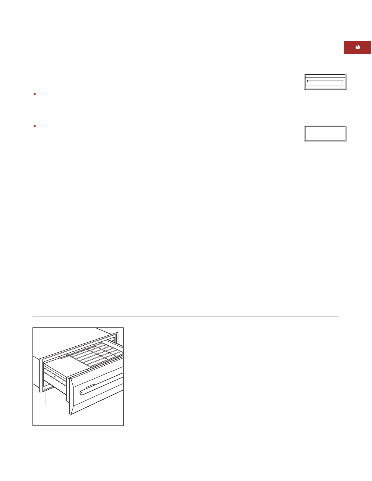
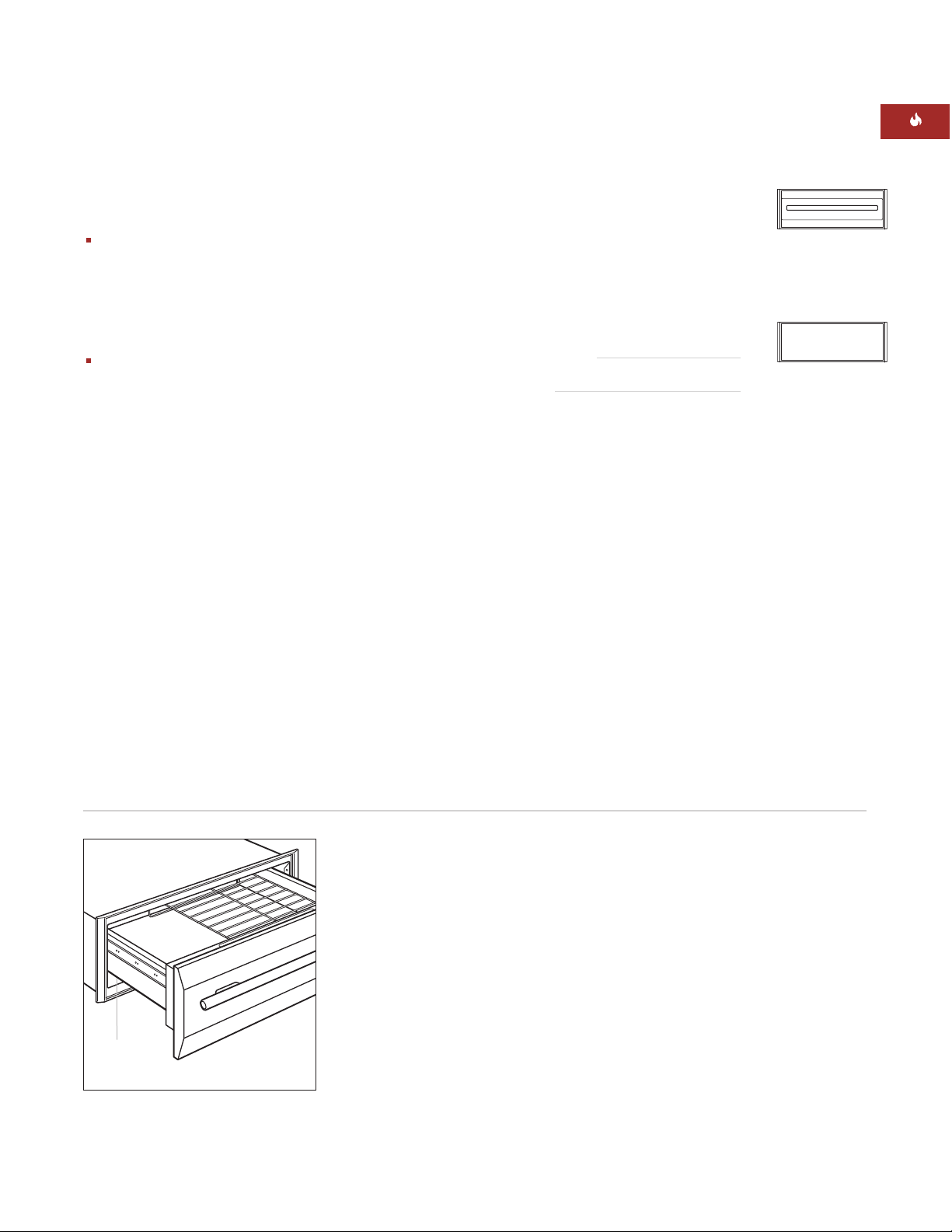
Record the model and serial numbers before
installing the warming drawer. Both numbers
are listed on the product rating plate, located
on the left front floor area of the inner cabinet.
To access the rating plate, the drawer must be
fully open. Refer to the illustration below.
Model Number ICBWWD30
Serial Number
5
INSTALLATION REQUIREMENTS
IMPORTANT NOTE:
This installation must be
completed by a qualified technician.
Installer:
Please read the entire Installation
Instructions prior to installation. Save these
instructions for the local inspector’s reference, then leave them with the homeowner.
Homeowner:
Please read and keep these
instructions for future reference and be sure
to read the entire Use & Care Information
prior to use.
Any questions or problems about the
installation should be directed to your Wolf
dealer. You can also visit our website
at wolfappliance.com.
IMPORTANT NOTE:
This appliance must be
installed in accordance with local codes. The
correct voltage, frequency and amperage must
be supplied to the appliance from a dedicated,
grounded circuit which is protected by a
properly sized circuit breaker or time delay
fuse. The proper voltage, frequency, and
amperage ratings are listed on the product
rating plate.
WOLF WARMING DRAWER
Rating plate location
Location of
rating plate
Model ICBWWD30
with Stainless Steel
Drawer Front
Model ICBWWD30
with Integrated
Drawer Front
Page 6

6
WOLF WARMING DRAWER
DRAWER FRONT OPTIONS
IMPORTANT NOTE:
Model ICBWWD30 must
be installed with a Wolf stainless steel or
integrated drawer front.
Classic Stainless Steel
WWDFRONT/S
Integrated Drawer Front
WWDFRONT/I
(accepts wood panel)
Drawer fronts are ordered and shipped as
sales accessories and include additional
installation instructions. Stainless steel drawer
fronts include a matching tubular handle.
The integrated drawer front accepts a custom
wood panel and handle to be provided by the
homeowner. Optional stainless steel tubular
handles in classic stainless steel are available
as sales accessories.
TOOLS AND MATERIALS REQUIRED
Wood screws or other hardware to install
the solid platform or runners that support
the warming drawer
51 mm x 51 mm or 51 mm x 102 mm
lumber for runners—runners must be able
to support 91 kg
51 mm x 51 mm or 51 mm x 102 mm
lumber for anti-tip block
Power saw
Level
Drill and 1,6 mm bit, 13 mm bit also for
integrated drawer front application
Phillips screwdriver
2 wood screws (provided)
Wood cleats for integrated drawer front
application
ACCESSORIES
Optional
accessories are
available through
your Wolf dealer.
BEFORE YOU START
Before you install the warming drawer,
make sure you have the Wolf accessory
drawer front called for in your installation.
IMPORTANT NOTE:
If you are installing
the warming drawer with integrated drawer
front in an inset panel application, make
sure that your cabinetry meets the
minimum 838 mm width and 635 mm depth
requirement for this installation.
Check with local utilities for electrical codes
that apply in your area. Local codes vary.
Installation, electrical connections and
grounding must comply with applicable
codes.
This appliance must be properly grounded.
Refer to Electrical Requirements on
page 14.
Make sure you have the tools and materials
necessary for proper installation.
Page 7
7
INSTALLATION INSTRUCTIONS
MODEL ICBWWD30
with Stainless Steel Drawer Front
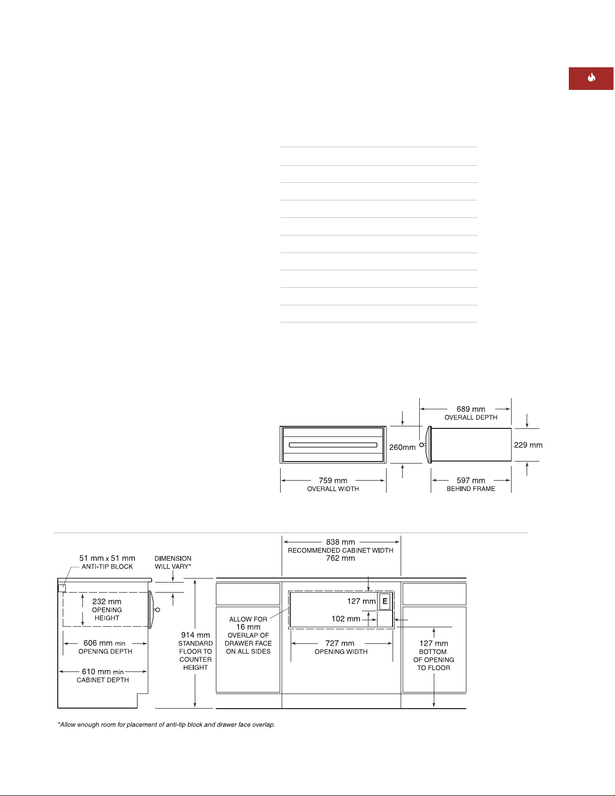
Overall Width 759 mm
Overall Height 260 mm
Overall Depth 689 mm
Depth Behind Frame* 597 mm
Minimum Cabinet Width 762 mm
Minimum Cabinet Depth 610 mm
Minimum Base Support 91 kg
Opening Width 727 mm
Opening Height 232 mm
Opening Depth 606 mm
*Allow 10 mm additional depth for cord thickness.
STAINLESS STEEL DRAWER FRONT
INSTALLATION SPECIFICATIONS
The following illustrations provide the overall
dimensions and installation specifications for
the Wolf warming drawer with a stainless steel
drawer front.
Wolf recommends using a 838 mm wide
cabinet for the warming drawer with stainless
steel drawer front. A minimum 762 mm wide
by 610 mm deep cabinet is required with a
minimum base support of 91 kg.
Refer to pages 16–17 for stainless steel drawer
front installation instructions. These instructions are also included with the stainless steel
drawer front kit.
UNDERCOUNTER INSTALLATION
For undercounter installations, 597 mm from
the bottom of the warming drawer opening to
the floor is recommended. It must be installed
a minimum of 127 mm above the floor or
25 mm above the toe kick.
The Wolf warming drawer with stainless steel
drawer front may be installed below an electric
or gas cooktop, provided the warming drawer
is fully enclosed, top and bottom. Allow
enough room for gas and electrical connections for the cooktop. Refer to installation
instructions for the cooktop for additional
specifications. Dimensions will vary according
to the specific installation.
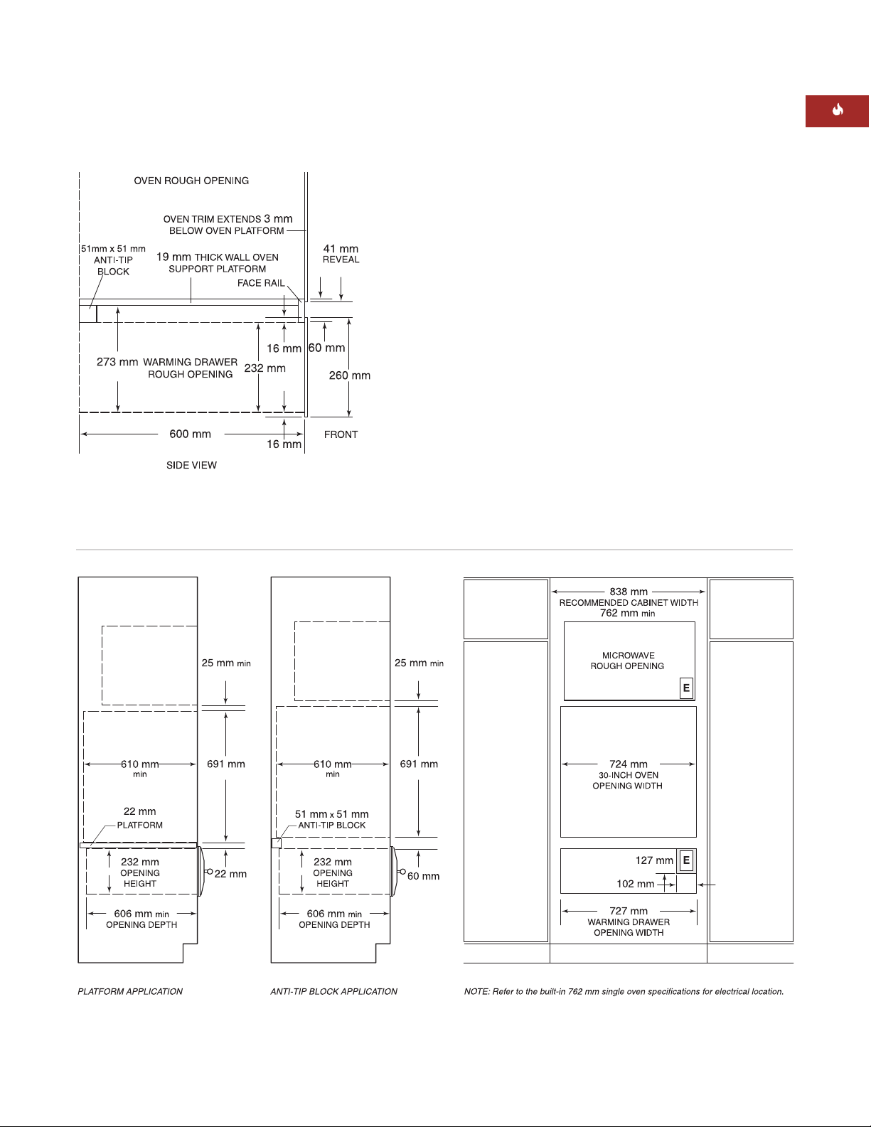
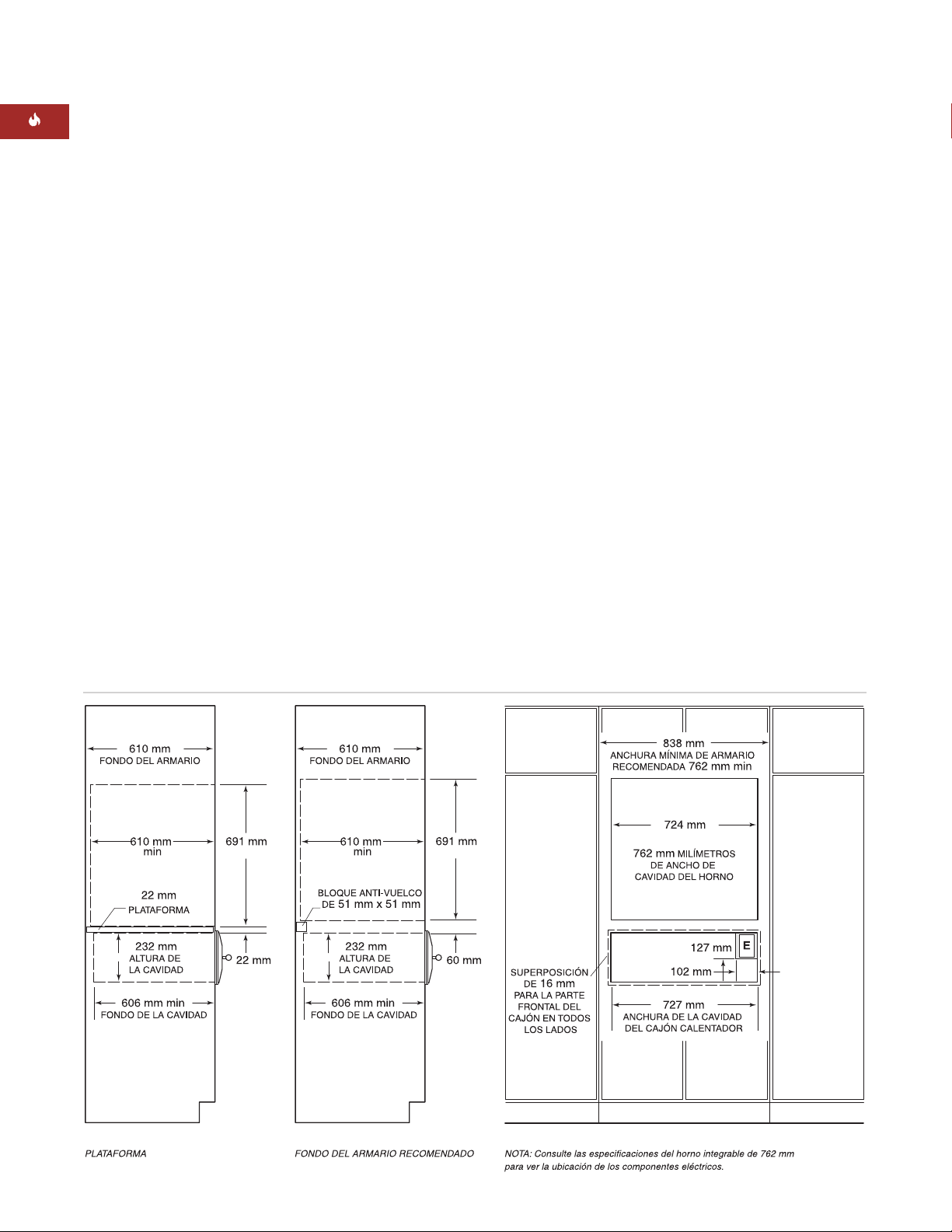
Overall Dimensions – Stainless Steel Drawer Front
Undercounter Installation – Stainless Steel Drawer Front
Page 8
8
WOLF WARMING DRAWER
STAINLESS STEEL DRAWER FRONT
INSTALLATION WITH BUILT-IN OVEN
The Wolf warming drawer with stainless steel
drawer front may be installed below or above
a Wolf 762 mm built-in single oven or below a
double oven, provided the warming drawer is
fully enclosed, top and bottom. Refer to the
illustration below. Also refer to installation
instructions provided with the built-in oven for
additional specifications. Dimensions will vary
according to the specific installation.
The Wolf warming drawer is designed and
agency approved for installation with Wolf
built-in ovens.
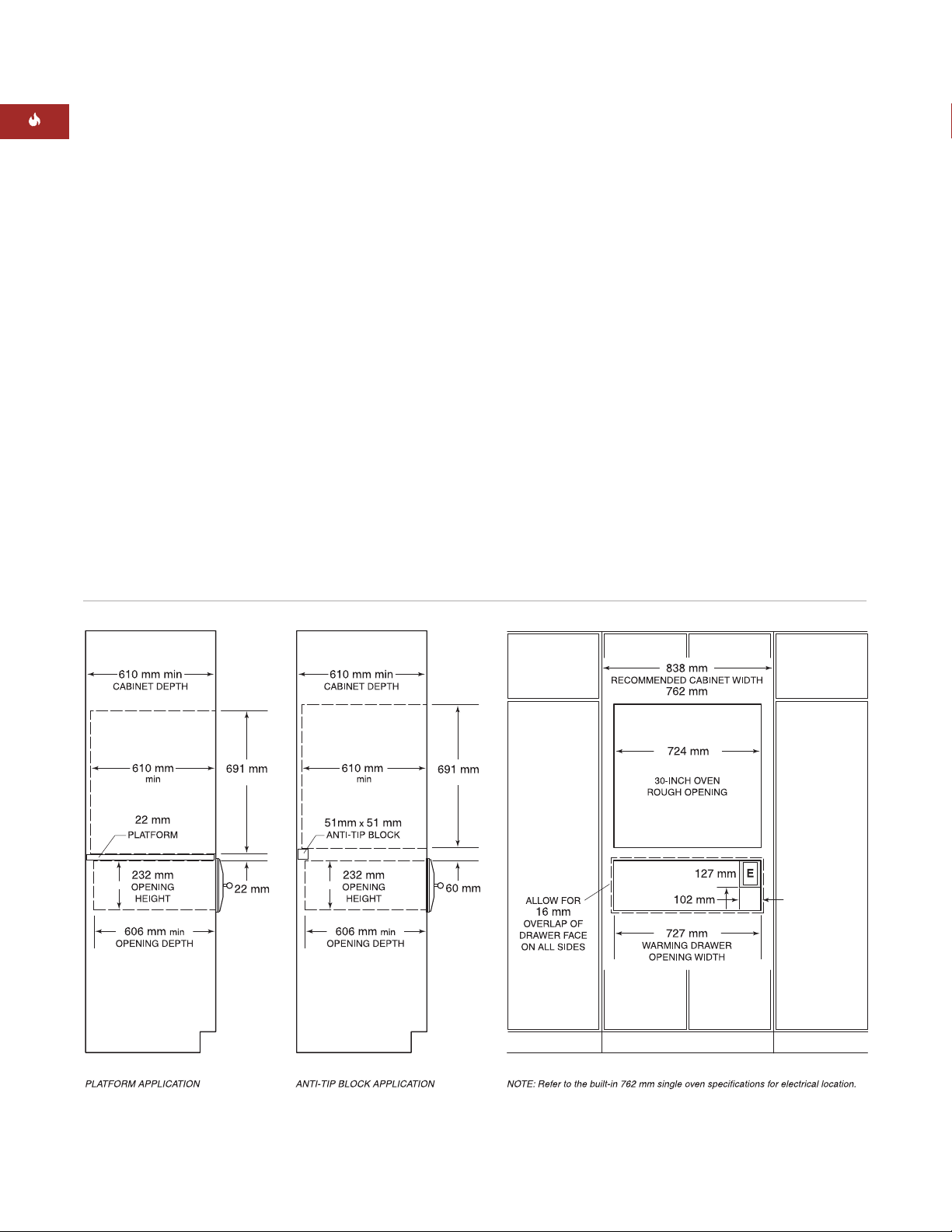
The warming drawer platform must be able to
support 91 kg. It must be a minimum of 25 mm
above the toe kick to allow for the overlap of
the warming drawer trim.
Installation with Built-In Oven – Stainless Steel Drawer Front
IMPORTANT NOTE:
Additional clearance
between warming drawer and oven openings
may be required. Check that oven supports do
not obstruct the interior dimensions required
for the warming drawer.
When the warming drawer is installed below
a built-in oven, a minimum of 60 mm between
warming drawer and oven openings is
required for placement of the anti-tip block. To
allow the warming drawer trim and the built-in
oven trim to meet, a 22 mm platform may be
used to separate the two openings. This will
act as the support platform for the oven and
the anti-tip device for the warming drawer.
Both applications are shown in the
illustration below.
IMPORTANT NOTE:
When the warming
drawer is installed above a built-in oven, a
22 mm platform is required to allow for
clearance of overlaps.
Page 9
9
INSTALLATION INSTRUCTIONS
Installation with Built-In Oven and Microwave – Stainless Steel Drawer Front
OPTIONAL INSTALLATIONS
The Wolf warming drawer with stainless steel
drawer front may be installed in combination
with a 762 mm single oven and microwave
oven with 762 mm trim, provided the warming
drawer is fully enclosed, top and bottom. Refer
to the illustration below. Also refer to installation instructions provided with the built-in
oven and microwave for additional specifications. Dimensions will vary according to the
specific installation.
The warming drawer platform must be able to
support 91 kg. It must be a minimum of 25 mm
above the toe kick to allow for the overlap of
the warming drawer trim.
The Wolf warming drawer with stainless steel
drawer front may be installed next to or above
another Wolf warming drawer, provided each
unit is fully enclosed, top and bottom.
Installation with Built-In Oven – Stainless Steel
Drawer Front
STAINLESS STEEL DRAWER FRONT
Page 10
10
WOLF WARMING DRAWER
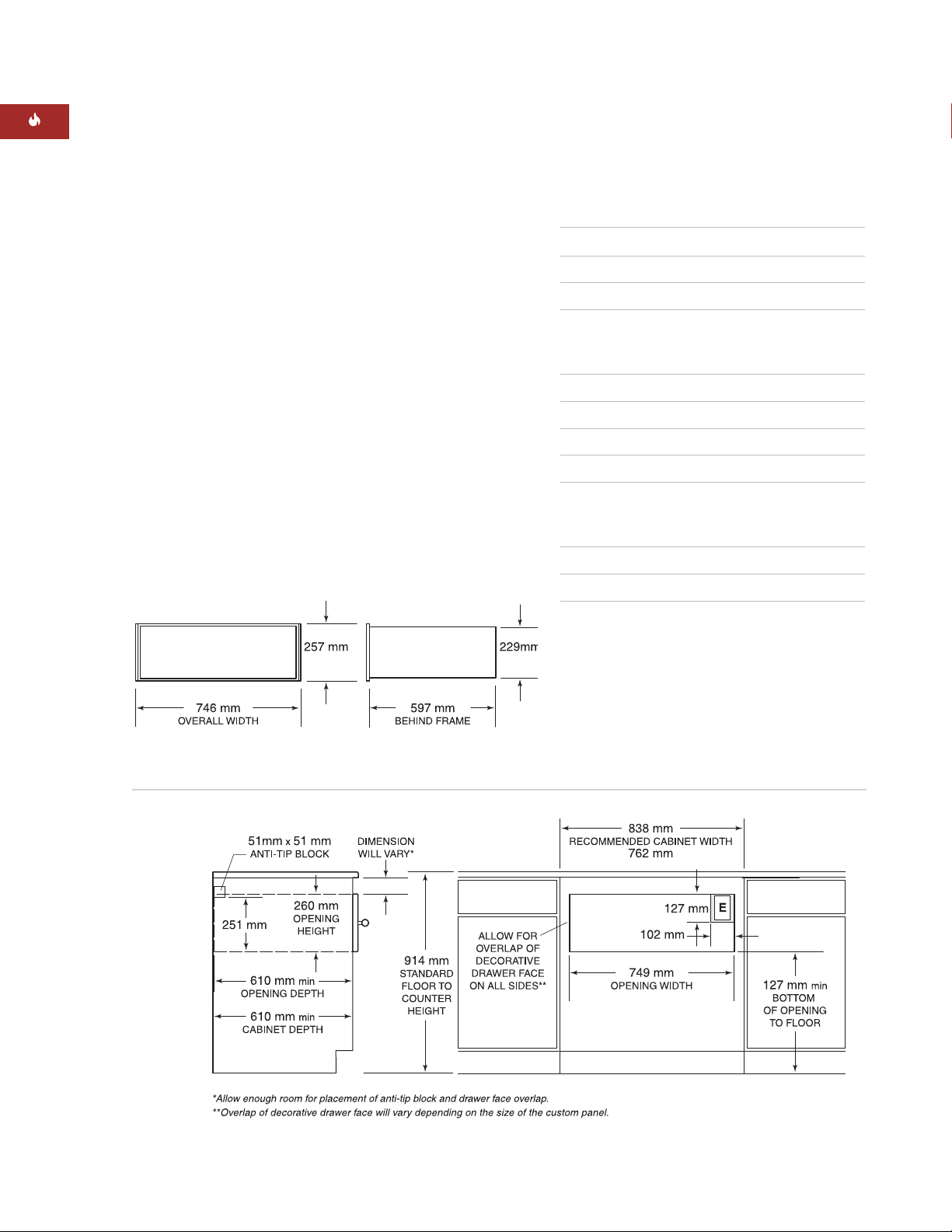
MODEL ICBWWD30
with Integrated Drawer Front
Overall Width 746 mm
Overall Height 257 mm
Overall Depth* (behind frame) 597 mm
Minimum Cabinet Requirements
Overlay 838 mm W x 610 mm D
Inset 838 mm W x 635 mm D
Minimum Base Support 91 kg mm
Opening Width 749 mm
Opening Height 260 mm
Opening Depth** 610 mm
Minimum Panel Size
Overlay 762 mm W x 264 mm H
Inset 746 mm W x 257 mm H
Minimum Panel Thickness 16 mm
Maximum Panel Weight 11 kg
*Allow 10 mm additional depth for cord thickness.
**For the inset application, add the thickness of
the drawer face to the opening depth.
Overall Dimensions – Integrated Drawer Front
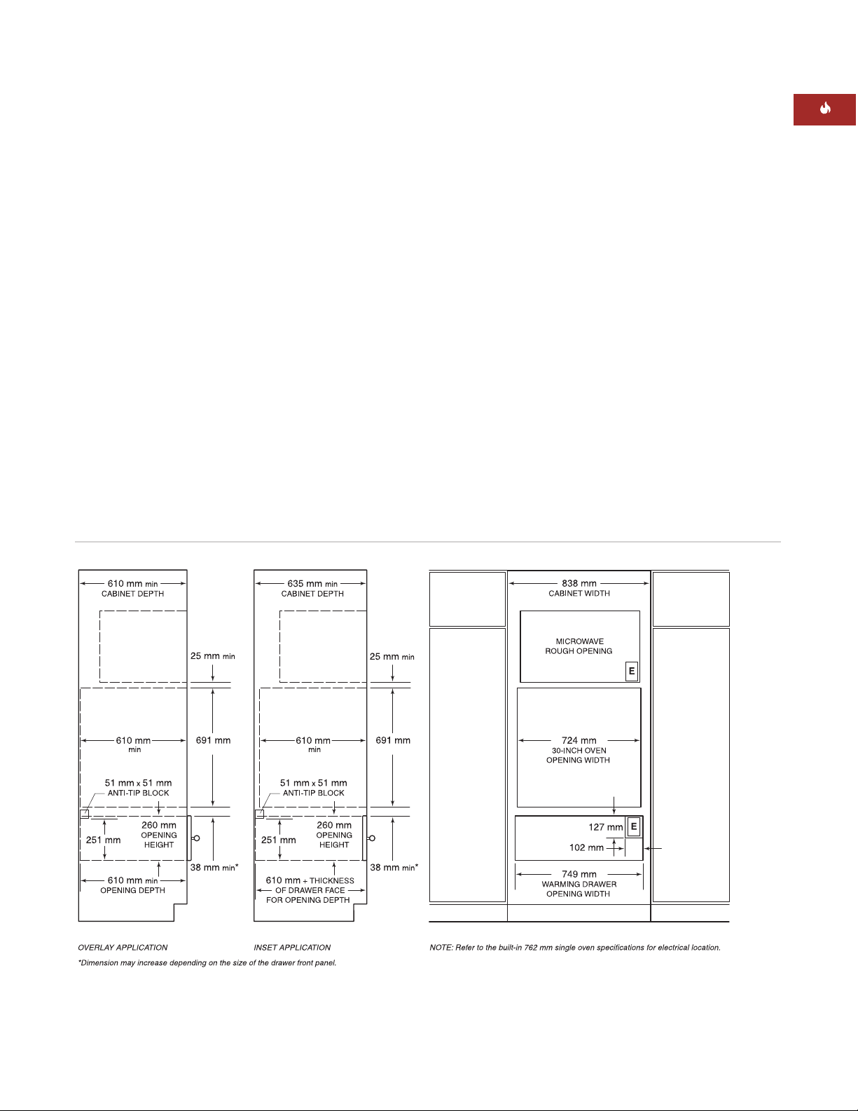
Integrated Drawer Front – Overlay Application
INTEGRATED DRAWER FRONT
INSTALLATION SPECIFICATIONS
The following illustrations provide the overall
dimensions and installation specifications for
the Wolf warming drawer with integrated
drawer front. The warming drawer with integrated drawer front can be used in an overlay
application or an inset panel application where
it will be completely recessed in to the cabinet.
Keep in mind that the size of the custom panel
for the warming drawer with integrated drawer
front will vary according to the specific installation. The following chart provides minimum
dimensions for the overlay and inset panel
applications.
Refer to pages 18–20 for integrated drawer
front installation instructions. These instructions are also included with the integrated
drawer front kit.
Page 11
11
INSTALLATION INSTRUCTIONS
Integrated Drawer Front – Inset Application
INTEGRATED DRAWER FRONT
OVERLAY APPLICATION
A minimum 838 mm wide by 610 mm deep
cabinet is required for the warming drawer
with integrated drawer front using the overlay
application. A minimum base support of 91 kg
is required. Refer to the illustration on page 10.
INSET APPLICATION
IMPORTANT NOTE:
The inset application
requires the warming drawer to be recessed
into the cabinet. A minimum 635 mm deep
cabinet is needed if you want the front panel
to be flush with surrounding cabinetry.
If you are installing the warming drawer with
integrated drawer front in an inset application,
a minimum 838 mm wide and 635 mm deep
cabinet is required for this installation. A
minimum base support of 91 kg is required.
Refer to the illustration below.
UNDERCOUNTER INSTALLATION
For undercounter installations, 597mm from
the bottom of the warming drawer opening to
the floor is recommended. It must be installed
a minimum of 127 mm above the floor or
25 mm above the toe kick.
The Wolf warming drawer with integrated
drawer front may be installed below a 762 mm
or 914 mm wide electric or gas cooktop,
provided the warming drawer is fully enclosed,
top and bottom. Refer to installation instructions for the cooktop for additional specifications. Dimensions will vary according to the
specific installation.
Page 12
12
WOLF WARMING DRAWER
IMPORTANT NOTE:
Additional clearance
between warming drawer and oven openings
may be required. Check that oven supports do
not obstruct the interior dimensions required
for the warming drawer.
When the warming drawer is installed below
a built-in oven, a minimum of 38 mm between
warming drawer and oven openings is
required for placement of the anti-tip block and
oven platform. When installed above a built-in
oven, a minimum of 22 mm is required.
IMPORTANT NOTE:
In an overlay application,
the amount of space between warming drawer
and built-in oven openings may need to be
increased depending on the size of the overlay
panel and the amount of overlap.
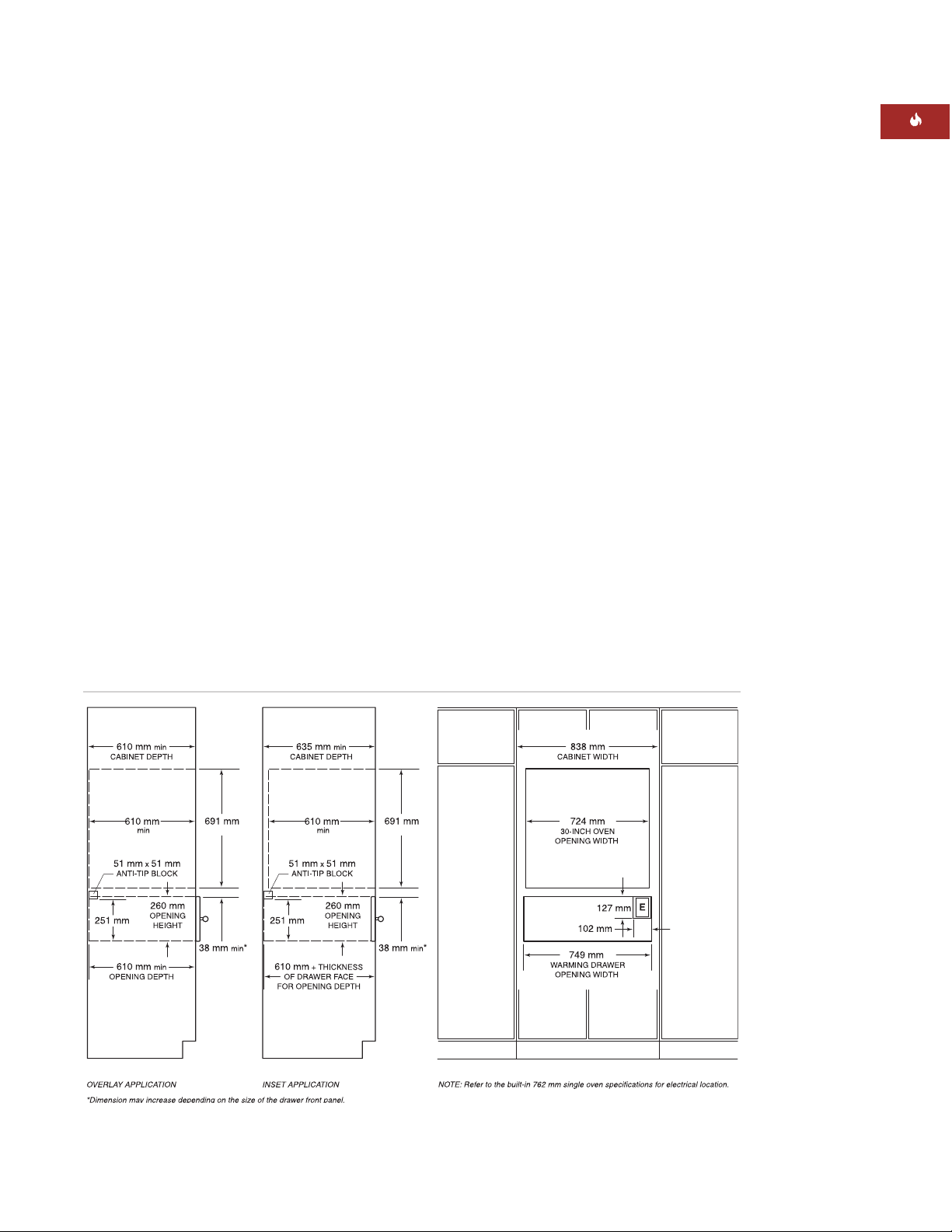
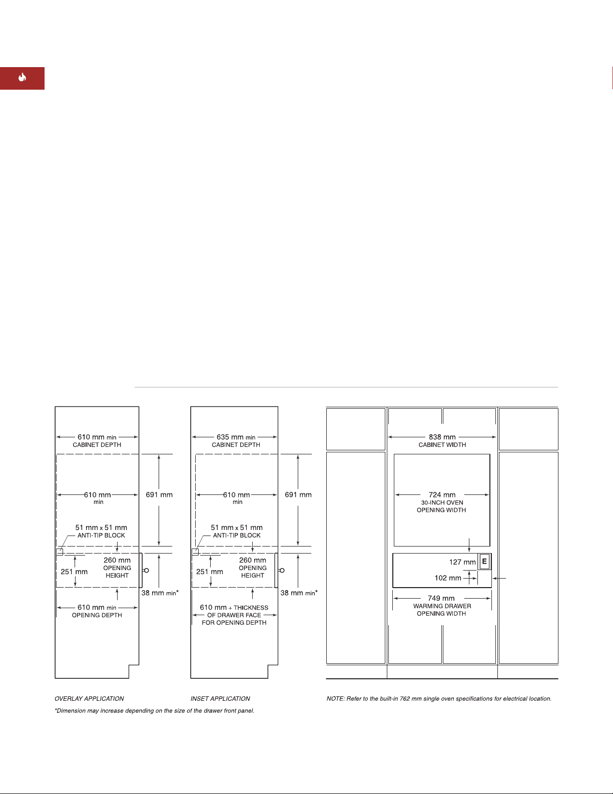
INTEGRATED DRAWER FRONT
INSTALLATION WITH BUILT-IN OVEN
The Wolf warming drawer with integrated
drawer front may be installed below or above
a Wolf 762 mm or 914 mm built-in single oven,
provided the warming drawer is fully enclosed,
top and bottom. Refer to the illustration below.
Also refer to installation instructions provided
with the built-in oven for additional specifications. Dimensions will vary according to the
specific installation.
The Wolf warming drawer is designed and
agency approved for installation with Wolf
built-in ovens.
The warming drawer platform must be able to
support 91 kg. It must be a minimum of 25 mm
above the toe kick to allow for the overlap of
the warming drawer trim.
Installation with Built-In Oven – Integrated Drawer Front
Page 13
13
INSTALLATION INSTRUCTIONS
Installation with 762 mm Built-In Oven and Microwave – Integrated Drawer Front
Refer to installation instructions provided with
the built-in oven and microwave for additional
specifications. Dimensions will vary according
to the specific installation.
The Wolf warming drawer with integrated
drawer front may be installed next to or above
another Wolf warming drawer, provided each
unit is fully enclosed, top and bottom.
INTEGRATED DRAWER FRONT
INSTALLATION OPTIONS
The Wolf warming drawer with integrated
drawer front may be installed in combination
with a 762 mm single built-in oven and
microwave with 762 mm trim, provided the
warming drawer is fully enclosed, top and
bottom. Refer to the illustration below.
The Wolf warming drawer with integrated
drawer front may also be installed in combination with a 914 mm single built-in oven and
microwave with 914 mm trim.
The warming drawer platform must be able to
support 91 kg. It must be a minimum of 25 mm
above the toe kick to allow for the overlap of
the warming drawer trim.
Page 14

In addition, be aware of local codes and ordinances when installing your service.
14
WOLF WARMING DRAWER
ELECTRICAL REQUIREMENTS
The Wolf warming drawer requires a separate,
grounded 220–240 V AC, 50/60 Hz power
supply and must be connected to an individual
properly grounded branch circuit and
protected by a 15 or 20 amp circuit breaker or
time delay fuse.
IMPORTANT NOTE:
The warming drawer
must be plugged into a mating 3-prong
ground ing-type electrical cord to minimize the
possibility of electric shock.
If the outlet is placed behind the unit, make
sure the outlet is flush with the back wall. For
location of the electrical outlet, refer to the
installation illustration for your specific
installation on pages 7–13.
If two warming drawers are installed side by
side, they can operate from the same electrical
outlet. A 30 amp circuit breaker is required for
this installation.
Do not use an extension cord or twoprong adapter. Electrical ground is
required on this appliance. Do not remove
the power supply cord ground prong.
The electrical outlet must be checked by
a qualified electrician to be sure that it is
wired with the correct polarity. Verify
that the outlet provides 220–240 V AC
and is properly grounded.
IMPORTANT
NOTE
You must follow
all local codes and
ordinances when
installing your
service.
Page 15

15
INSTALLATION INSTRUCTIONS
CABINET SUPPORTS
IMPORTANT NOTE:
When the warming
drawer is installed with a built-in oven,
additional clearance between openings may be
required. Check that oven supports do not
obstruct the interior dimensions required for
the warming drawer.
The warming drawer with stainless steel
drawer front may be supported by either a
solid platform, 51 mm x 51 mm runners or
51 mm x 102 mm runners. The platform or
runners must be level, rigidly mounted and
flush with the bottom edge of the opening.
They must be able to support 91 kg.
If an integrated drawer front is used, it must be
supported by a 16 mm solid platform. The
platform will need to be recessed and allow for
overlap of the warming drawer collar. Refer to
page 18 for additional details. The platform
must be level, rigidly mounted and must be
able to support 91 kg.
IMPORTANT NOTE:
Make sure that the
platform or runners are level. There is no way
to level the warming drawer once it has been
installed.
UNPACK THE WARMING DRAWER
Unpack the warming drawer on a flat surface.
Remove all packaging materials and tape from
inside the warming drawer and discard. Do not
discard the package containing the two wood
screws needed for installation.
Page 16
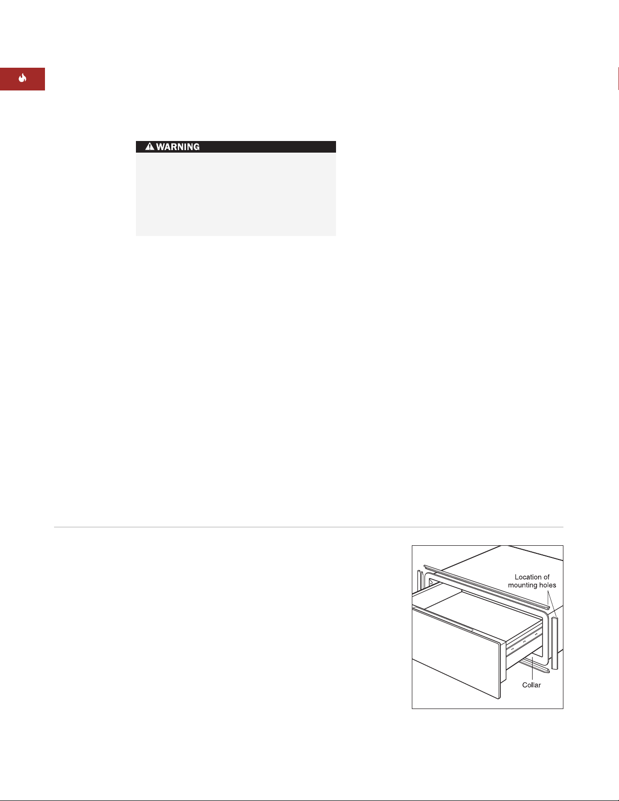
INSTALL WARMING DRAWER TRIM
Remove all packaging materials from the trim.
The stainless steel drawer front kit comes with
two long trim pieces for the top and bottom
collar of the warming drawer and two short
trim pieces for the sides. Each trim piece has a
groove that fits over the edge of the collar.
Refer to the illustration below.
Place one of the long trim pieces on the top
collar of the warming drawer so the groove in
the trim fits on the top collar.
Next, place one of the small side trim pieces
on the left collar edge. The top trim and side
trim should nest together. On the backside of
the trim pieces are mounting holes. Use the
small 8 mm long screws provided in the kit to
secure these two pieces together.
Repeat this process to attach the right side and
bottom trim.
16
WOLF WARMING DRAWER
STAINLESS STEEL FRONT PANEL
INSTALL ANTI-TIP BLOCKING
Install a 51 mm x 51 mm or 51 mm x 102 mm
anti-tip block against the rear cabinet wall.
When the warming drawer is installed below a
built-in oven, you may use a 22 mm thick
platform to allow the warming drawer trim and
the oven trim to meet. The platform will act as
an anti-tip device for the warming drawer. Both
applications are shown in the illustrations on
page 8.
An anti-tip block or platform must be
installed to prevent the warming drawer
from tipping forward while opened when
loaded. Failure to do so could result in
personal injury and damage to the
cabinet.
Install warming drawer trim
Page 17
17
INSTALLATION INSTRUCTIONS
STAINLESS STEEL FRONT PANEL
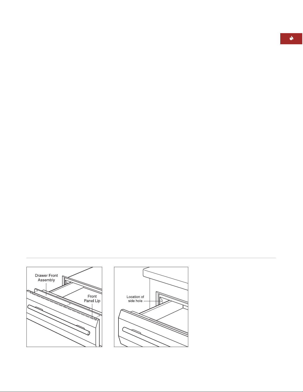
INSTALL FRONT PANEL
Remove all packaging materials from the
handle and front panel. Gently remove the
protective covering from the stainless steel
front panel. The adhesive covering should peel
away from the surface cleanly, but any remaining residue should be cleaned off with a mild
detergent.
To attach the handle to the front panel, line up
holes in the standoffs and handle with holes
on the front panel. Insert handle screws
through the holes in the front panel and
tighten screws to the front panel.
Slide the top lip of the front panel over the
drawer front. Insert three screws in the top of
the front panel lip through the drawer front
assembly and tighten screws. Insert three
screws in the bottom of the front panel
through the drawer front assembly and tighten
screws. Refer to the illustration below.
Turn power off to the electrical outlet.
INSTALL WARMING DRAWER
Slide the left corner of the warming drawer
into the opening. If the electrical outlet is
installed inside the opening, plug the power
cord into the outlet. The excess cord should be
coiled behind or beside the unit. If the outlet
is located in an adjacent cabinet, thread the
power cord through the hole in the cabinet
wall. Push the drawer back into the opening
until the trim meets the cabinet front. Make
sure the power cord does not get trapped
under the warming drawer.
IMPORTANT NOTE:
Do not lift up on the
handle to push the drawer into place. Doing so
could scratch the control panel.
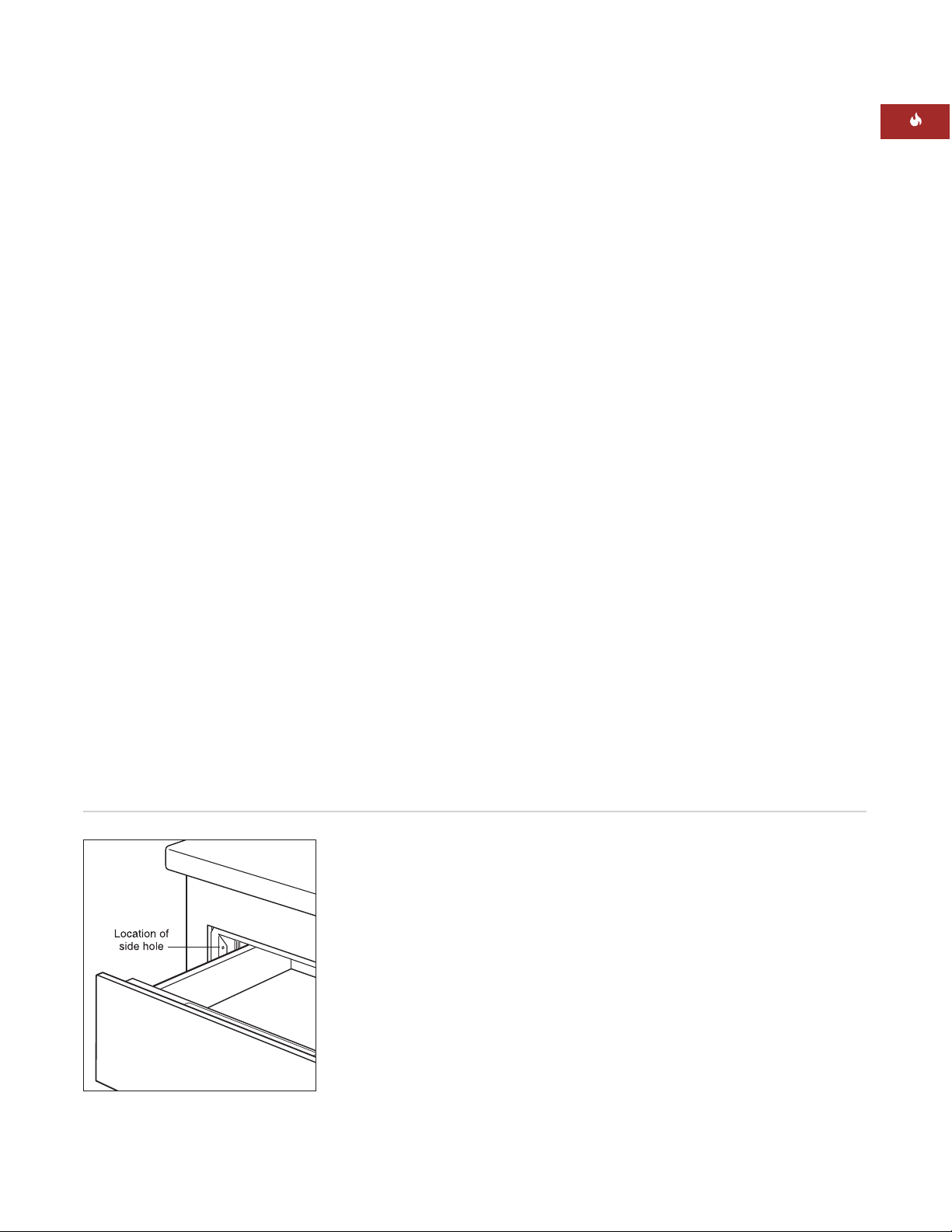
Open the warming drawer to its full extension.
Drill pilot holes in each side hole, located
toward the front on each side of the warming
drawer. Install the wood screws provided with
the unit. Refer to the illustration below.
Turn power back on to the electrical outlet.
Warming drawer installationAttach handle
Page 18

18
INTEGRATED FRONT PANEL
INSTALL CLEATS AND PLATFORM
For an overlay or inset application, you will
need to install a recessed platform and cleats
of the following dimensions into the opening.
Top Cleat Dimensions
749 mm W x 13 mm H x 51 mm D
Side Cleat Dimensions
13 mm W x 232 mm H x 51 mm D
Platform Dimensions
749 mm W x 16 mm H x 603 mm D
Depth of platform may increase depending
cabinet depth.
For an overlay application, the platform and
cleats will need to be recessed 5 mm. For an
inset application, they must be recessed 5 mm
plus the thickness of the decorative drawer
panel, allowing the decorative panel to be
flush with the front of the cabinet. Be sure to
rigidly mount the platform so that it can
support a minimum of 91 kg. Refer to the illustrations below.
IMPORTANT NOTE:
In an overlay application,
be sure to recess the cleats no more than
5 mm. Recessing deeper than this may cause
the drawer to not close properly.
WOLF WARMING DRAWER
IMPORTANT NOTE:
Be sure to finish the
inside lip of the opening and the front face of
the shelf and cleats. Some of these areas will
be visible when the drawer is open.
IMPORTANT NOTE:
Be aware of the location
of the mounting holes on the warming drawer
frame to make sure the screws used to attach
the cleats do not interfere with the screw holes
for mounting the warming drawer.
Recessed cleats and platform –
inset application
Recessed cleats and platform –
overlay application
Page 19
19
INSTALLATION INSTRUCTIONS
Warming drawer installation
INTEGRATED FRONT PANEL
INSTALL ANTI-TIP BLOCKING
Install a 51 mm x 51 mm or 51 mm x 102 mm
anti-tip block against the rear cabinet wall as
shown in the installation illustration for your
specific installation on pages 11–13.
INSTALL WARMING DRAWER
Turn power off to the electrical outlet. Slide the
left corner of the warming drawer into the
opening. If the electrical outlet is installed
inside the opening, plug the power cord into
the outlet. The excess cord should be coiled
behind or beside the unit. If the outlet is
located in an adjacent cabinet, thread the
power cord through the hole in the cabinet
wall. Push the unit back into the opening until
the warming drawer collar meets up with the
recessed cleats and platform. Make sure the
power cord does not get trapped under the
warming drawer.
Open the drawer to its full extension. Drill pilot
holes in each side hole, one located toward
the front on each side of the warming drawer.
Install the wood screws provided with the
warming drawer. Refer to the illustration
below. Turn power back on to the electrical
outlet.
Page 20
20
WOLF WARMING DRAWER
INTEGRATED FRONT PANEL
INSTALL FRONT PANEL TO DRAWER
Disconnect the communications line from
communications jack. The communications
jack is removed by depressing retaining clip
from front of mounting panel, then pushing
the retaining clip side of jack through
mounting panel first, then pivoting jack out of
mounting panel. Place removed communications jack inside drawer frame assembly.
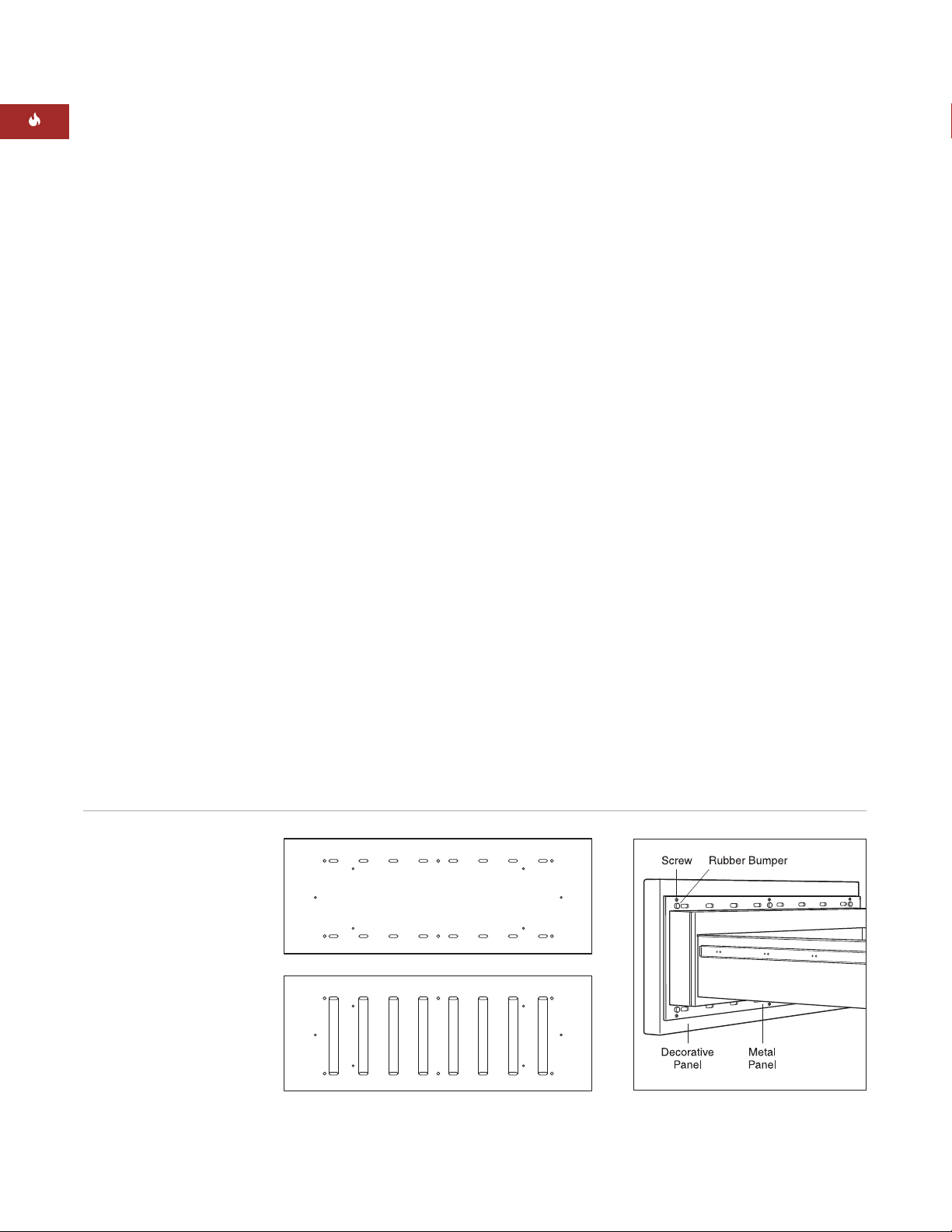
Place the metal panel from the integrated
drawer front onto the back of the decorative
front panel. Trace all of the holes in the metal
panel onto the decorative panel.
Draw a line from the edge of the oblong holes
to the corresponding oblong hole below it.
The markings on the back of the decorative
panel should look like the bottom panel illustration below.
For every round marking on the decorative
panel (12 locations, six for screw heads and six
for the backs of the rubber bumpers), drill a
12.7 mm hole, 6.35 mm deep in the back of the
panel.
Route out the rectangular areas (8 locations)
marked on the back of the decorative panel
6.35 mm deep.
Attach the handle hardware to the front of the
decorative panel. The integrated drawer front
kit does not include a handle. This allows the
homeowner to match handle hardware with
the surrounding cabinetry.
Using the six screws that came with the
warming drawer, install the metal panel from
the integrated drawer front kit onto the
warming drawer front. Make sure the brushed
side of the metal panel is facing the warming
drawer.
Install the six rubber bumpers, provided with
the warming drawer front kit, onto the metal
panel. Attach the decorative panel to the
warming drawer by screwing through the back
of the warming drawer into the decorative
front panel using the six, 12.7 mm mounting
screws provided with the kit.
Location of bumpers and mounting
screws
Back view of decorative panel
Page 21

21
CONTACT
INFORMATION
Website:
wolfappliance.com
TROUBLESHOOTING
IMPORTANT NOTE:
If the warming drawer
does not operate properly, follow these
troubleshooting steps:
Verify that power is being supplied to the
warming drawer.
Check electrical connections to ensure that
the installation has been completed
correctly.
Refer to the Troubleshooting Guide in the
Wolf Warming Drawer Use & Care
Information.
If the warming drawer still does not work,
contact your Wolf dealer or regional distributor. Do not attempt to repair the warming
drawer yourself.
IF YOU NEED SERVICE
For service in your area, contact either your
Wolf dealer or visit the Locator page of our
website,
wolfappliance.com
to find the
regional distributor by country.
When calling for service, you will need the
model and serial numbers of the warming
drawer. Both numbers are listed on the
product rating plate, located on the left
front floor area of the inner cabinet. To
access the rating plate, the drawer must
be fully open. Refer to the illustration on
page 5.
INSTALLATION INSTRUCTIONS
The information and images are the copyright
property of Wolf Appliance, Inc., an affiliate of
Sub-Zero, Inc. Neither this book nor any information or images contained herein may be copied
or used in whole or in part without the express
written permission of Wolf Appliance, Inc., an
affiliate of Sub-Zero, Inc.
©Wolf Appliance, Inc. all rights reserved.
Page 22
A medida que siga las instrucciones que
aparecen en esta guía, encontrará símbolos
de ADVERTENCIA y PRECAUCIÓN. Esta información en recuadros es important e para
instalar el equipo de Wolf de forma segura
y eficaz. Existen dos tipos de posibles
riesgos que pueden producirse durante
una instalación.
Otro tipo de anotación que nos gustaría
indicar es la que se incluye en NOTA IMPORTANTE: En esta nota se resalta la información
que resulta especialmente importante para
que la instalación se realice sin problemas.
indica una situación en la que pueden
producirse heridas personales leves
o daños secundarios en el producto si
no se siguen las instrucciones.
indica que existe peligro de que
se produzcan heridas personales
graves o incluso puede provocar la
muerte si no se siguen las instrucciones.
WOLF®es una marca comercial registrada de Wolf Appliance, Inc.
INFORMACIÓN
DE CONTACTO
Página Web:
wolfappliance.com
Page 23
Apunte la referencia del modelo y el número
de serie antes de instalar el cajón calentador.
Esta información aparece en la placa de datos
del producto situada en la parte izquierda
delantera del mueble interior. Para ver la placa
de datos, es necesario abrir el cajón totalmente. Observe la siguiente ilustración.
Referencia del modelo ICBWWD30
Número de serie
23
REQUISITOS DE INSTALACIÓN
NOTA IMPORTANTE:
Esta instalación debe
ser realizada por un técnico cualificado.
Instalador:
Lea las instrucciones de instalación antes de llevar a cabo la instalación.
Guarde estas instrucciones para que el
inspector local pueda utilizarlas como
refe-rencia y, a continuación, entréguelas
al propietario del aparato.
Propietario:
Lea y guarde estas instrucciones para que pueda utilizarlas como
referencia en el futuro y asegúrese de
leer la guía de uso y mantenimiento
antes de utilizar el aparato.
Si tiene alguna pregunta o problema relacionado con la instalación, debe ponerse
en contacto con su distrubuidor de Wolf.
También puede visitar nuestra página Web
wolfappliance.com.
NOTA IMPORTANTE:
Este aparato debe ser
instalado siguiendo las normativas nacionales
correspondientes. Se debe aplicar al aparato el
voltaje, la frecuencia y el amperaje adecuados
desde una instalación eléctrica resistente con
toma de tierra protegida por un fusible de
retardo. El voltaje, la frecuencia y el amperaje
se muestran en la placa de datos del producto.
CAJÓN CALENTADOR DE WOLF
Ubicación de la placa de datos
Ubicación de
la placa de
datos
Modelo ICBWWD30
con frente de cajón
de acero inoxidable
Modelo ICBWWD30
con frente de cajón
que lleve un panel
integrado
Page 24

24
CAJÓN CALENTADOR DE WOLF
OPCIONES DEL FRENTE DE CAJÓN
NOTA IMPORTANTE:
El modelo ICBWWD30
debe instalarse con un panel frontal integrado
o un frente de acero inoxidable de Wolf.
Acero inoxidable
Frente de cajón integrado
WWDFRONT/I
(admite panel de madera)
Los frentes de cajón se piden y se envían
como accesorios e incluyen instrucciones
de instalación adicionales. Los frentes de
cajón de acero inoxidable incluyen un tirador
tubular a juego.
El frente de cajón integrado admite un panel
de madera fabricado a medida y un tirador
que tendrá que elegir a parte el propietario.
También hay disponibles tiradores tubulares
de acero inoxidable como accesorios
opcionales.
HERRAMIENTAS Y MATERIALES
NECESARIOS
Tornillos de madera u otras piezas para
instalar la plataforma o las guías de deslizamiento que sujetan el cajón calentador
Listones de 51 mm x 51 mm ó 51 mm x
102 mm para las guías de desplazamiento
que deben aguantar un peso de 91 kg
Listones de 51 mm x 51mm ó
51 mm x 102 mm para el bloque anti-vuelco
Sierra mecánica
Nivel
Taladro y broca de 1,58 mm, broca de 12,7
mm también para la aplicación del frente
de cajón integrado
Destornillador Phillips
2 tornillos de madera (incluidos)
Listón de madera para el frente de
cajón integrado
ACCESORIOS
Podrá disponer
de los accesorios
opcionales en el
distribuidor de
Wolf correspondiente.
ANTES DE COMENZAR
Antes de instalar el cajón calentador,
asegúrese de que tiene preparado el frente
de cajón de Wolf para que sea instalado.
NOTA IMPORTANTE:
Si está instalando
el cajón calentador con el frente integrado
para un uso empotrado, asegúrese de que
el mobiliario cumple las medidas mínimas
de 838 mm de ancho y 635 mm de fondo.
Consulte la normativa eléctrica correspondiente a su área con los servicios públicos
locales. La normativa local puede variar.
La instalación, las conexiones eléctricas
y la conexión a tierra deben cumplir la
normativa aplicable.
Este aparato debe estar conectado a tierra
de manera correcta. Consulte la sección
Requisitos eléctricos en la página 32.
Compruebe que tiene las herramientas y
los materiales necesarios para realizar la
instalación de manera correcta.
WWDFRONT/S
Page 25

25
INSTRUCCIONES DE INSTALACIÓN
MODELO ICBWWD30
con frente de cajón de acero inoxidable
Ancho total 759 mm
Altura total 260 mm
Fondo total 689 mm
Fondo detrás del marco* 597 mm
Ancho mínimo del mueble 762 mm
Fondo mínimo del mueble 610 mm
Soporte mínimo de la base 91 kg
Ancho de la cavidad 727 mm
Altura de la cavidad 232 mm
Fondo de la cavidad 606 mm
*Deje un fondo adicional de 10 mm para el cable.
FRENTE DE CAJÓN DE ACERO
INOXIDABLE
ESPECIFICACIONES DE LA
INSTALACIÓN
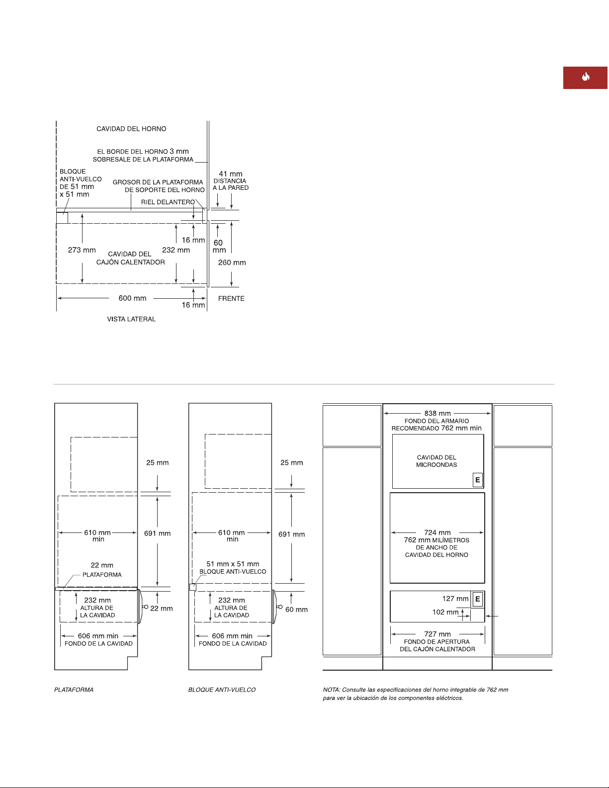
La siguiente ilustración proporciona las
medidas totales y las especificaciones de la
instalación para el cajón calentador de Wolf
con el frente de acero inoxidable.
Wolf le recomienda utilizar un mueble con
un ancho de 838 mm para el cajón calentador
con el frente de acero inoxidable. Se requiere
un mueble con unas medidas de 762 mm de
ancho por 610 mm de fondo con una base
que soporte un mínimo de 91 kg.
Consulte las páginas 34–35 para obtener las
instrucciones de instalación del frente de
cajón de acero inoxidable. Estas instrucciones
también se incluyen con el kit del frente de
cajón de acero inoxidable.
INSTALACIÓN BAJO ENCIMERA
Para instalar el cajón bajo una encimera, se
recomienda mantener una espacio de 597 mm
desde la parte inferior del cajón calentador
hasta el suelo. El cajón debe instalarse con
un mínimo de 127 mm sobre el nivel del
suelo ó 25 mm sobre el rodapié.
El cajón calentador con frente de acero inoxidable puede instalarse debajo de un cocina de
gas o de una placa vitrocerámica siempre que
el cajón calentador quede completamente
ajustado en la parte superior e inferior. Deje el
suficiente espacio para las conexiones eléctricas o de gas de la cocina. Consulte las instrucciones de instalación de la cocina para obtener
especificaciones adicionales. Las medidas
puede variar dependiendo de la instalación.
Dimensiones totales: Frente de cajón de acero inoxidable
Instalación bajo encimera: Frente de cajón de acero inoxidable
Page 26
26
CAJÓN CALENTADOR DE WOLF
FRENTE DE CAJÓN DE ACERO
INOXIDABLE
INSTALACIÓN CON HORNO
INTEGRABLE
El cajón calentador de Wolf con frente de acero
inoxidable puede instalarse debajo de o sobre
un horno sencillo integrable de 762 mm o
debajo de un horno doble siempre que el
cajón calentador quede completamente
ajustado en la parte superior e inferior.
Observe la siguiente ilustración. Consulte
también las instrucciones de instalación
que se proporcionan con el horno integrable
para obtener especificaciones adicionales.
Las medidas puede variar dependiendo de
cada instalación.
El cajón calentador de Wolf está diseñado
y aprobado por el organismo regulador
corres-pondiente para que se pueda instalar
con hornos integrables de Wolf.
La plataforma del cajón calentador debe
aguantar un peso de 91 kg. Debe dejar un
espacio mínimo de 25 mm por encima del
rodapié para dejar un margen suficiente
para la superoposición del borde del cajón
calentador.
Instalación con horno integrable – Frente de cajón de acero inoxidable
NOTA IMPORTANTE:
Se necesita dejar un
espacio adicional entre la cavidad del cajón
calentador y del horno. Compruebe que los
soportes del horno no obstruyen las medidas
interiores requeridas para el cajón calentador.
Cuando instale el cajón calentador debajo
de un horno integrable, necesitará dejar un
espacio mínimo de 60 mm entre la cavidad
del cajón calentador y la del horno para poder
colocar el bloque anti-vuelco. Para que el
borde del cajón calentador y el borde del
horno integrable queden unidos, puede
utilizar una plataforma de 22 mm entre las
dos aperturas. Esta plataforma actúa como
una plataforma de soporte para el horno y el
dispositivo anti-vuelco lo hace para el cajón
calentador. Ambos usos se muestran en la
siguiente ilustración.
NOTA IMPORTANTE:
Cuando el cajón calentador se instala sobre el horno integrable, es
necesario colocar una plataforma de 22 mm
para dejar suficiente margen para las superposiciones.
Page 27
27
INSTRUCCIONES DE INSTALACIÓN
Instalación con horno incorporado y microondas: frente de cajón de acero inoxidable
INSTALACIONES OPCIONALES
El cajón calentador de Wolf con frente de acero
inoxidable puede instalarse en combinación con
un horno sencillo de 762 mm y con un microondas con un borde de 762 mm siempre que el
cajón calentador quede completamente ajustado
a la parte superior e inferior. Observe la siguiente ilustración. Consulte también las instrucciones de instalación que se proporcionan con
el horno integrable y el microondas para
obtener especificaciones adicionales. Las
medidas pueden variar dependiendo de cada
instalación.
La plataforma del cajón calentador debe
aguantar un peso de 91 kg. Debe dejar un
mínimo de 25 mm por encima del rodapié para
que haya suficiente margen para la superposición del borde del cajón calentador.
El cajón calentador de Wolf con frente de acero
inoxidable puede instalarse al lado de o debajo
de otro cajón calentador de Wolf, siempre que el
cajón calentador quede completamente ajustado
al cerrarse en la parte superior e inferior.
Instalación con horno incorporado: frente de
cajón de acero inoxidable
FRENTE DE CAJÓN DE ACERO
INOXIDABLE
Page 28
28
CAJÓN CALENTADOR DE WOLF
MODELO ICBWWD30
con frente de cajón integrado
Ancho total 746 mm
Altura total 257 mm
Fondo total* (marco posterior) 597 mm
Requisitos mínimos del mueble
Revestible 838 A x 610 F
Empotrado 838 A x 635 F
Soporte mínimo de la base 91 kg
Ancho de la cavidad 749 mm
Altura de la cavidad 260 mm
Fondo de la cavidad** 610 mm
Tamaño mínimo del panel
Revestible 762 A x 264 Altura
Empotrado 746 A x 257 Altura
Grosor mínimo del panel 16 mm
Peso máximo del panel 11 kg
*Deje un fondo adicional de 10 mm para el cable.
**Para aplicaciones empotrables, sume el grosor
de la parte delantera del cajón al fondo de la
cavidad.
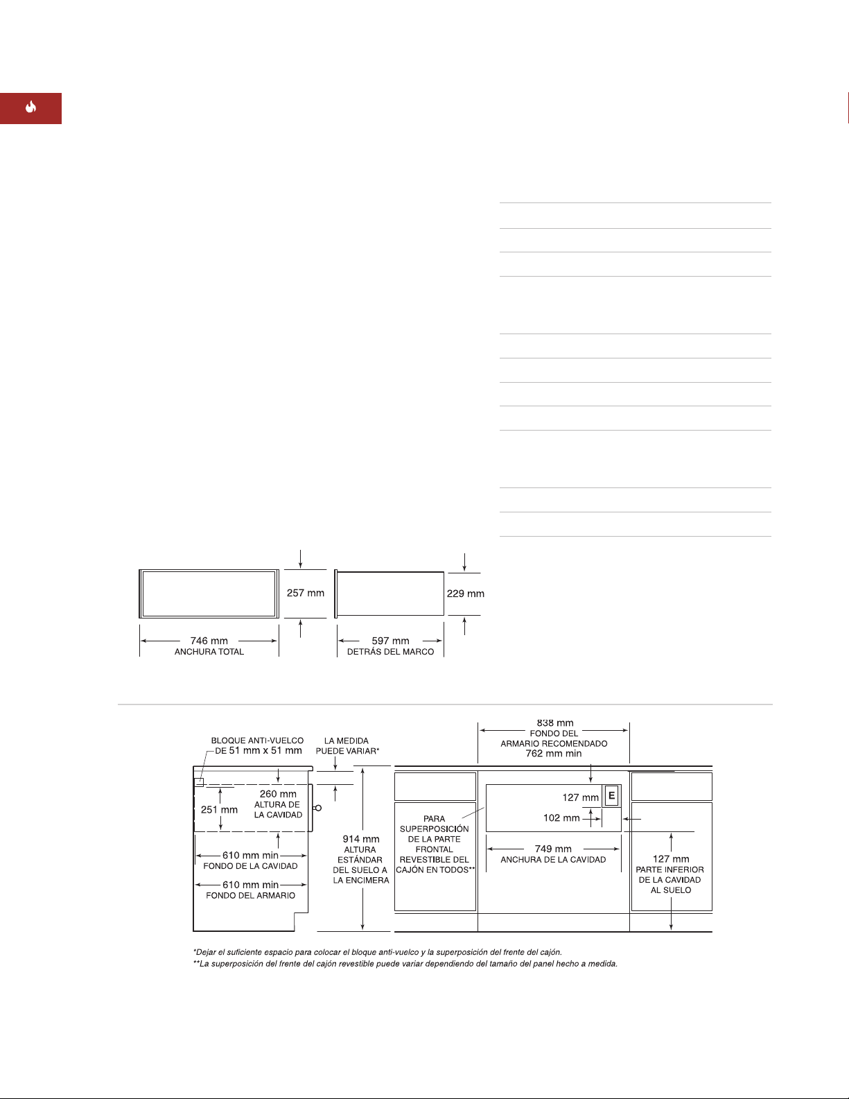
Medidas totales: frente de cajón integrado
Frente de cajón integrado: aplicación revestible
FRENTE DE CAJÓN INTEGRADO
ESPECIFICACIONES DE LA
INSTALACIÓN
Las siguientes ilustraciones proporcionan las
medidas generales y las especificaciones de
la instalación para el cajón calentador de Wolf
con frente de acero inoxidable. El cajón calentador con frente integrado se puede utilizar en
aplicaciones empotradas o revestible, por lo
que el cajón quedará completamente acoplado
en el mueble.
Recuerde que el tamaño del panel fabricado
a medida para el cajón calentador con frente
integrado puede variar dependiendo de cada
instalación. La siguiente figura proporciona
las medidas mínimas para el cajón revestido
o empotrado.
Consulte las páginas 36-38 para observar
las instrucciones de instalación del frente
del cajón integrado. Estas instrucciones
también se incluyen con el kit del frente del
cajón integrado.
Page 29
29
INSTRUCCIONES DE INSTALACIÓN
Frente de cajón integrado: empotrado
FRENTE DE CAJÓN INTEGRADO
APLICACIÓN REVESTIBLE
Se requiere un mueble con un ancho de
838 mm por un fondo de 610 mm mínimo para
el cajón calentador con frente integrado si es
una instalación revestible. Se requiere un
soporte de base que aguante un peso de 91 kg
mínimo. Consulte la ilustración de la página 28.
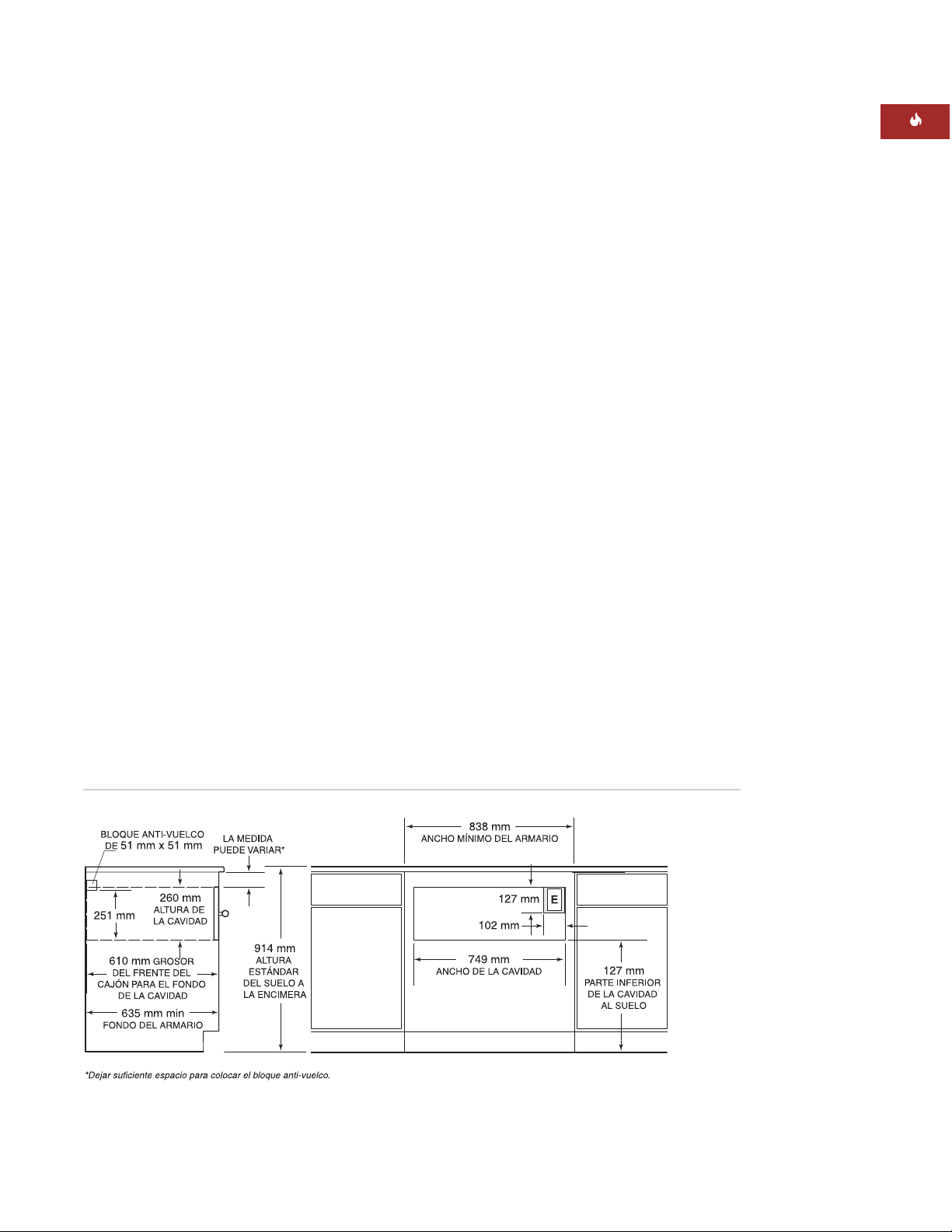
APLICACIÓN PARA EMPOTRAR
NOTA IMPORTANTE:
Para empotrar el
aparato en un mueble será necesario que
el cajón calentador quede completamente
acoplado dentro del mueble. Si desea que el
panel del frente se nivele con el mobiliario
circundante, necesitará un mueble con un
fondo mínimo de 635 mm.
Si desea empotrar el cajón calentador con el
frente integrado, necesitará un mueble con
un ancho de 838 mm y un fondo de 635 mm
como mínimo para realizar este tipo de instalación. Se requiere un soporte de base que
aguante un peso de 91 kg mínimo. Observe
la siguiente ilustración.
INSTALACIÓN BAJO ENCIMERA
Para la instalación bajo encimera, se
recomienda dejar un espacio de 597 mm desde
la parte inferior del cajón calentador hasta el
suelo. Debe instalarse con un mínimo de
127 mm sobre el nivel del suelo ó 25 mm
sobre el rodapié.
El cajón calentador con frente integrado puede
instalarse debajo de un cocina de gas o de una
placa vitrocerámica con un ancho de 762 mm
ó 914 mm siempre que el cajón calentador
quede completamente ajustado al cerrarse,
tanto en la parte inferior como en la parte
superior. Consulte las instrucciones de instalación de la placa vitrocerámica para obtener
especificaciones adicionales. Las medidas
puede variar dependiendo de cada instalación.
Page 30

30
CAJÓN CALENTADOR DE WOLF
NOTA IMPORTANTE:
Se necesita dejar un
espacio adicional entre el cajón calentador y
las cavidades del horno. Compruebe que los
soportes del horno no obstruyen las medidas
internas requeridas para el cajón calentador.
Cuando instale el cajón calentador debajo de
un horno integrable, necesitará dejar un
espacio mínimo de 38 mm entre las cavidades
del cajón calentador y del horno para poder
colocar el bloque anti-vuelco y la plataforma
del horno. Cuando lo instale encima de un
horno integrable, necesitará dejar un espacio
mínimo de 22 mm.
NOTA IMPORTANTE:
En caso de que el cajón
se vaya a revestir, es posible que deba dejar
más espacio entre las cavidades del cajón
calentador y del horno integrable dependiendo
del tamaño del panel y de la superposición.
FRENTE DE CAJÓN
INTEGRADO
INSTALACIÓN CON HORNO
INTEGRABLE
El cajón calentador de Wolf con frente integrado puede instalarse debajo o encima de un
horno integrable Wolf de 762 mm ó 914 mm
siempre que el cajón calentador quede
completamente ajustado al cerrarse, tanto
en la parte inferior como en la parte superior.
Observe la siguiente ilustración. Consulte
también las instrucciones de instalación que
se proporcionan con el horno integrable para
obtener más información. Las medidas puede
variar dependiendo de cada instalación.
El cajón calentador de Wolf está diseñado y
aprobado por el organismo regulador correspondiente para que se pueda instalar con
hornos integrables de Wolf.
La plataforma del cajón calentador debe
aguantar un peso de 91 kg. Debe dejar un
espacio mínimo de 25 mm por encima del
rodapié para que haya margen suficiente
para la superposición del borde del cajón
calentador.
Instalación con horno integrable: frente de cajón integrado
Page 31

31
INSTRUCCIONES DE INSTALACIÓN
Instalación con horno y microondas integrables de 762 mm: frente de cajón integrado
Consulte las instrucciones de instalación que
se proporcionan con el horno y el microondas
integrables para ver información más específica. Las medidas pueden variar dependiendo
de cada instalación.
El cajón calentador de Wolf con frente de cajón
integrado puede instalarse al lado de o debajo
de otro cajón calentador de Wolf, siempre que
el cajón calentador quede completamente
ajustado al cerrarse, tanto en la parte superior
como en la inferior.
FRENTE DE CAJÓN
INTEGRADO
OPCIONES DE INSTALACIÓN
El cajón calentador de Wolf con frente de cajón
integrado puede instalarse en combinación
con un horno sencillo de 762 mm y con un
microondas que tenga un borde de 762 mm
siempre que el cajón calentador quede
completamente ajustado al cerrarse tanto en
la parte superior como en la inferior. Observe
la siguiente ilustración.
El cajón calentador de Wolf con frente de cajón
integrable también se puede instalar en combinación con un microondas y un horno sencillo
integrable de 914 mm que tenga un borde de
914 mm.
La plataforma del cajón calentador debe
aguantar un peso de 91 kg. Debe dejar un
espacio mínimo de 25 mm por encima del
rodapié para que haya margen suficiente
para la superposición del borde del cajón
calentador.
Page 32

Además, deberá cumplir la normativa eléctrica
nacional al instalar el aparato.
32
CAJÓN CALENTADOR DE WOLF
REQUISITOS ELÉCTRICOS
El cajón calentador de Wolf debe ser conectado a una red eléctrica individual con toma
a tierra de 220–240 V CA, 50/60 Hz, 2500 w y
con un fusible protector de 15 amperios.
NOTA IMPORTANTE:
El cajón calentador
debe ser conectado a una base enchufe
monofásica con toma a tierra.
Si la toma se coloca detrás de la unidad,
asegúrese de que ésta esté al mismo nivel que
la pared trasera. Para conocer la ubicación de
la toma eléctrica, consulte la ilustración de la
instalación para hacerlo correctamente en las
páginas 25–31.
Si los dos cajones calentadores se instalan
contiguos, pueden funcionar con la misma
toma eléctrica. Es recomendable que este
aparato se conecte a una instalación eléctrica
con cortacircuitos de seguridad de 30
amperios.
No utilice alargadores ni adaptadores.
Este aparato debe conectarse a tierra. Si
la base enchufe es diferente a la clavija de
conexión que lleva el aparato, no cambie
nunca la clavija del aparato, sino la base
del enchufe.
La toma de corriente debe ser revisada por
un electricista cualificado para comprobar
que el cableado se ha realizado con la
polaridad correcta. Compruebe que la
toma proporciona 220–240 V CA y que est
á conectado a tierra de manera correcta.
NOTA
IMPORTANTE:
Deberá cumplir
todas las ordenanzas y normativas
nacionales cuando
instale el aparato.
Page 33

33
INSTRUCCIONES DE INSTALACIÓN
SOPORTES DE LOS MUEBLES
NOTA IMPORTANTE:
Cuando el cajón calentador se instale con un horno integrable,
necesitará dejar un espacio adicional entre las
dos cavidades. Compruebe que los soportes
del horno no obstruyen las medidas interiores
requeridas para el cajón calentador.
El cajón calentador con frente de acero inoxidable puede sujetarse con una plataforma
sólida, guías con rodamiento de 51 mm x
51 mm ó de 51 mm x 102 mm. La plataforma o
las guías de rodamiento deben estar niveladas
y montadas sólidamente y niveladas con el
borde inferior de la apertura. Deben aguantar
un peso de 91 kg.
Si utiliza un frente de cajón integrado, debe
sujetarlo con una plataforma sólida de 16 mm.
Necesitará que la plataforma se acople para
permitir la superposición del anillo del cajón
calentador. Consulte la página 36 si desea
obtener información adicional. La plataforma
debe estar nivelada, montada solidamente y
debe soportar un peso de 91 kg.
NOTA IMPORTANTE:
Asegúrese de que la
plataforma o las guías de rodamiento están
niveladas. El cajón calentador no se puede
mover después de que se haya instalado.
DESEMBALAJE DEL CAJÓN
CALENTADOR
Desembale el cajón calentador en una superficie plana. Retire todos los materiales de
embalaje del cajón calentador y tírelos. No
tire el paquete que incluye los dos tornillos
de madera ya que son necesarios para realizar
la instalación.
Page 34
INSTALACIÓN DEL BORDE DEL
CAJÓN CALENTADOR
Retire todos los materiales de embalaje del
borde. El kit del frente de acero inoxidable
incluye dos bordes largos para el anillo inferior
y superior del cajón calentador y dos bordes
cortos para los laterales. Cada borde tiene una
ranura que encaja en el borde del anillo.
Observe la siguiente ilustración.
Coloque uno de los bordes largos en el anillo
superior del cajón calentador para que la
ranura del borde encaje en el anillo superior.
A continuación, coloque uno de los bordes
pequeños en el borde del anillo izquierdo. El
borde superior y el borde lateral deben encajar
correctamente. En el reverso del borde están
los agujeros de montaje. Utilice los tornillos
largos de 8 mm que se proporcionan en el kit
para asegurar estas dos piezas.
Repita este proceso para unir el borde inferior
y el lateral derecho.
34
CAJÓN CALENTADOR DE WOLF
PANEL FRONTAL DE ACERO
INOXIDABLE
INSTALACIÓN DEL BLOQUE
ANTI-VUELCO
Instale un bloque anti-vuelco de 51 mm x
51 mm ó 51 mm x 102 mm contra la pared del
mueble trasero. Cuando el cajón calentador se
instala debajo de un horno integrable, puede
utilizar una plataforma gruesa de 22 mm para
que el borde del cajón calentador y el borde
del horno se unan. La plataforma actuará
como un dispositivo anti-vuelco para el cajón
calentador. Ambos usos se muestran en las
ilustraciones de la página 26.
Debe instalar una plataforma o un bloque
anti-vuelco para evitar que el cajón calentador se incline hacia adelante mientras
se abre cuando está cargado. Si no lo
instala, es posible que se puedan
producir heridas graves o daños en
el mueble.
Instalación del borde del cajón
calentador
Page 35
35
INSTRUCCIONES DE INSTALACIÓN
PANEL FRONTAL DE ACERO
INOXIDABLE
INSTALACIÓN DEL PANEL FRONTAL
Retire todos los materiales del embalaje del
tirador y del panel frontal. Retire con cuidado
la cubierta protectora del panel frontal de
acero inoxidable. Debe retirar la cubierta
adhesiva de la superficie y limpiar cualquier
residuo que quede con detergente suave.
Para unir el tirador al panel frontal, alinee
los agujeros en los puntos correspondientes
y el tirador con los agujeros del panel frontal.
Inserte los tornillos del tirador en los agujeros
del panel frontal y apriete los tornillos en el
panel frontal.
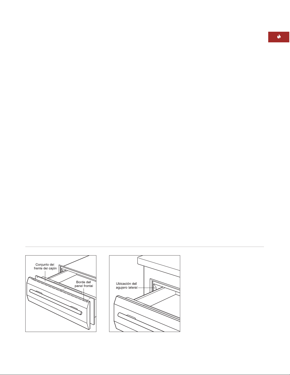
Introduzca el borde superior del panel frontal
por el frente del cajón. Inserte tres tornillos en
la parte superior del borde del panel frontal
por el conjunto del frente del cajón y apriete
los tornillos. Inserte tres tornillos en la parte
inferior del panel frontal por el conjunto del
frente del cajón y apriete los tornillos. Observe
la siguiente ilustración.
Desconecte el aparato de la red eléctrica.
INSTALACIÓN DEL CAJÓN
CALENTADOR
Introduzca la esquina izquierda del cajón calentador por la apertura. Si la toma de corriente
se instala dentro de la cavidad, enchufe el
cable de alimentación en la toma. El cable que
sobre debe enrollarse por detrás o al lado de
la unidad. Si la toma está situada en un
mueble adyacente, pase el cable por el agujero
de la pared del mueble. Empuje la parte
trasera del cajón hacia la cavidad hasta que el
borde toque el frente del armario. Asegúrese
de que el cable no se queda atrapado debajo
del cajón calentador.
NOTA IMPORTANTE:
No levante el tirador
para colocar el cajón en su lugar. Si lo hace
puede rayar el panel de control.
Abra el cajón calentador hasta el final. Taladre
un agujero guía en cada agujero lateral situado
en la parte delantera del lateral del cajón
calentador. Instale los tornillos de madera que
se incluyen con la unidad. Observe la siguiente
ilustración.
Vuelva a conectar la unidad a la red eléctrica.
Instalación del cajón calentadorInstalación del tirador
Page 36
36
PANEL FRONTAL INTEGRADO
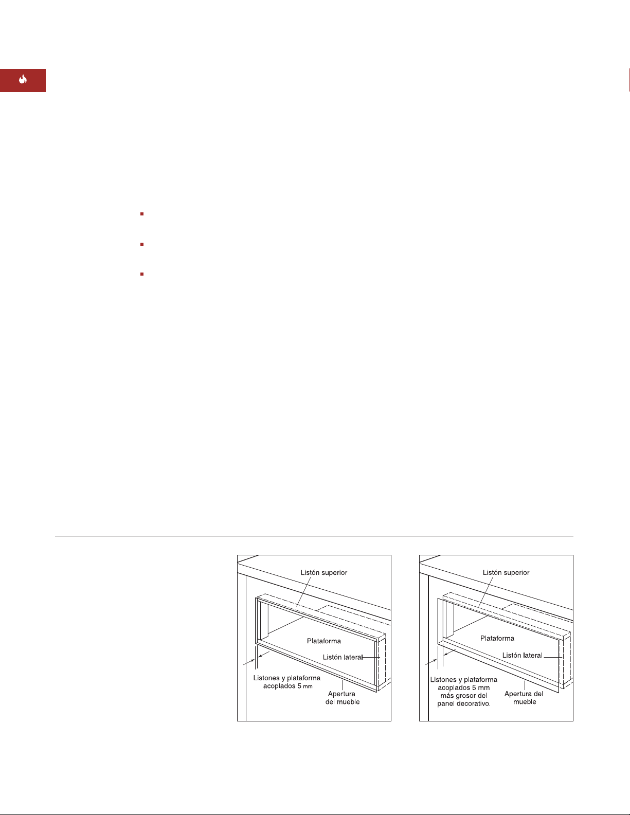
INSTALACIÓN DE LOS LISTONES
Y DE LA PLATAFORMA
Tanto para una instalación revestible como
para una instalación empotrada, necesitará
instalar una plataforma y unos listones con
las siguientes dimensiones.
Dimensiones del listón superior
749 mm A x 13 mm Alto x 51 mm F
Dimensiones del listón lateral
13 mm A x 232 mm Alto x 51 mm F
Dimensiones de la plataforma
749 mm A x 16 mm Alto x 603 mm F
El fondo de la plataforma puede aumentar
dependiendo de la profundidad del mueble.
Para una instalación revestible, es necesario
acoplar la plataforma y los listones 5 mm.
Para una instalación empotrada, éstos deberán
introducirse 5 mm más el grosor del panel
decorativo para que el panel decorativo quede
nivelado con la parte delantera del mueble.
Asegúrese de montar la plataforma de manera
correcta para que pueda aguantar un peso
mínimo de 91 kg. Observe la siguiente ilustración.
NOTA IMPORTANTE:
En una aplicación
revestida, compruebe que los listones no
se acoplan más de 5 mm. Si los introduce
más, es posible que el cajón no se cierre
de manera correcta.
CAJÓN CALENTADOR DE WOLF
NOTA IMPORTANTE:
Asegúrese de pulir
el borde interior de la apertura y la parte
delantera del estante y de los listones. Algunas
de estas áreas quedarán al descubierto cuando
se abra el cajón.
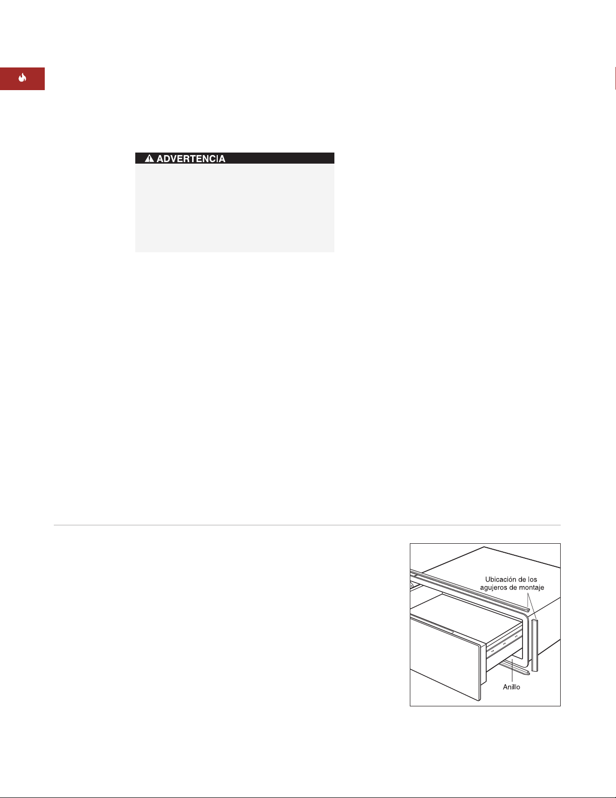
NOTA IMPORTANTE:
Recuerde la ubicación
de los agujeros de montaje del marco del
cajón calentador para asegurarse de que los
tornillos que ha utilizado para unir los listones
no interfieren con los agujeros de los tornillos
para el montaje del cajón calentador.
Acoplamiento de los listones y de
la plataforma: empotrado
Acoplamiento de los listones y de
la plataforma: aplicación revestible
Page 37
37
INSTRUCCIONES DE INSTALACIÓN
Instalación del cajón calentador
PANEL FRONTAL INTEGRADO
INSTALACIÓN DEL BLOQUE ANTIVUELCO
Instale un bloque anti-vuelco de 51 mm x
51mm ó 51mm x 102 mm en la pared del
mueble trasero tal y como se muestra en la
ilustración de la instalación para obtener la
instalación específica en las páginas 29 – 31.
INSTALACIÓN DEL CAJÓN
CALENTADOR
Desconecte el aparato de la red eléctrica.
Introduzca la esquina izquierda del cajón calentador por la apertura. Si la toma de corriente se
instala dentro de la cavidad, enchufe el cable
de alimentación en la toma. El cable que sobre
debe enrollarse por detrás o al lado de la
unidad. Si la toma está situada en un mueble
adyacente, pase el cable por el agujero de la
pared del mueble. Introduzca la unidad en la
cavidad hasta que el anillo del cajón calentador
toque los listones y la plataforma que colocó
anteriormente. Asegúrese de que el cable no
queda atrapado debajo del cajón calentador.
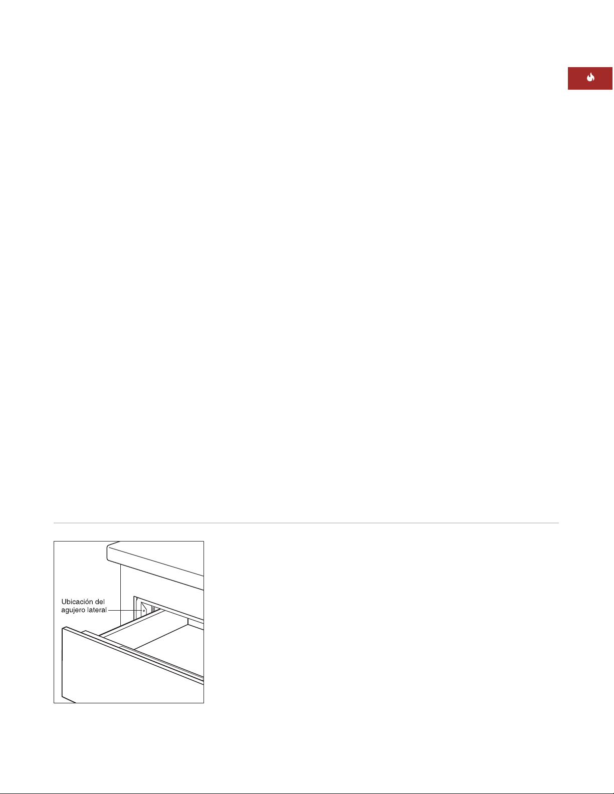
Abra el cajón hasta el final. Taladre unos
agujeros guía en cada agujero lateral, uno está
situado hacia la parte delantera de cada uno
de los laterales del cajón calentador. Instale los
tornillos de madera que se incluyen con el cajón
calentador. Observe la siguiente ilustración.
Vuelva a conectar la unidad a la red eléctrica.
Page 38

38
CAJÓN CALENTADOR DE WOLF
PANEL FRONTAL INTEGRADO
INSTALACIÓN DEL PANEL FRONTAL
EN EL CAJÓN
Desconecte la línea de comunicaciones del
enchufe para comunicaciones. El enchufe para
comunicaciones se extrae presionando el sujetador de retención de la parte delantera del
panel de montaje y, a continuación, pasando el
lateral del sujetador de retención del enchufe
por el panel de montaje en primer lugar y, a
continuación, girando hacia fuera el enchufe
del panel de montaje. Coloque el enchufe de
comunicaciones que ha retirado en el conjunto
del frente de cajón.
Coloque el panel de metal del frente del cajón
integrado en la parte trasera del panel
delantero decorativo. Trace todos los agujeros
del panel de metal en el panel decorativo.
Dibuje una línea desde el borde de los
agujeros alargados hasta el agujero alargado
correspondiente que hay por debajo. Las
marcas de la parte trasera del panel decorativo
deben ser como las que aparecen en la ilustración del panel inferior que se muestra a
continuación.
Para cada marca redonda del panel decorativo
(12 ubicaciones, seis para las cabezas de los
tornillos y seis para la parte trasera de los
topes de goma), haga un agujero de 12,7 mm
con una profundidad de 6 mm en la parte
posterior del panel.
Trace las áreas rectangulares (8 ubicaciones)
marcadas en la parte trasera del fondo de
6 mm del panel decorativo.
Una las piezas del tirador a la parte delantera
del panel decorativo. El kit del frente de cajón
integrado no incluye el tirador. De esta
manera, el propietario puede elegir un tirador
que haga juego con el mobiliario circundante.
Utilizando los seis tornillos que se proporcionan con el cajón calentador, instale el panel
de metal incluido en el kit del frente del cajón
integrado en el frente del cajón calentador.
Asegúrese de que el lado pulido del panel
de metal da al cajón calentador.
Instale los seis topes de goma que se proporcionan con el kit del frente del cajón calentador
en el panel de metal. Coloque el panel decorativo en el cajón calentador atornillando la parte
trasera del cajón calentador en el panel frontal
decorativo utilizando los seis tornillos de
12,7 mm y los tornillos de montaje de 6 mm
que se proporcionan con el kit.
Ubicación de los topes y de los
tornillos de montaje
Vista trasera del panel decorativo
Page 39

39
INFORMACIÓN DE
CONTACTO
Página Web:
wolfappliance.com
SOLUCIÓN DE PROBLEMAS
NOTA IMPORTANTE:
Si el cajón calentador
no funciona correctamente, siga estos
pasos de localización y solución de problemas:
Compruebe que el cajón calentador está
conectado al suministro eléctrico.
Compruebe las conexiones eléctricas para
asegurarse de que la instalación se ha
llevado a cabo de manera correcta.
Consulte la Guía de localización y solución
de problemas en la guía de uso y mantenimiento del cajón calentador.
Si el cajón calentador continúa sin
funcionar, póngase en contacto con el
distribuidor de Wolf o con un distribuidor
regional. No intente realizar ninguna
reparación en el cajón calentador.
SI NECESITA ASISTENCIA
TÉCNICA
Para buscar el servicio técnico de su
área, póngase en contacto con su
distribuidor de Wolf o visite la página
Web,
wolfappliance.com
, para buscar el
distribuidor más cercano.
Le recomendamos que anote la referencia
del modelo y el número de serie del cajón
calentador cuando llame para solicitar
ayuda. Esta información aparece en la
placa de datos del producto situada en
la parte izquierda delantera del armario
interior. Para ver la placa de datos, es necesario abrir el cajón totalmente. Consulte la
ilustración de la página 23.
INSTRUCCIONES DE INSTALACIÓN
La información y las imágenes que se incluyen en
este libro son propiedad de Wolf Appliance, Inc., una
filial de Sub-Zero, Inc. Este documento junto con la
información y las imágenes que en él se incluyen no
pueden copiarse ni utilizarse, total ni parcialmente,
sin el consentimiento por escrito de Wolf Appliance,
Inc., una filial de Sub-Zero, Inc.
©Wolf Appliance, Inc. se reserva todos los derechos.
Page 40
Vous remarquerez tout au long de ce manuel
d’instruc tions les mentions AVERTISSEMENT
et MISE EN GARDE, destinées à fournir des
recommandations importantes afin d’assurer
la sécurité et l’efficacité de l’installation de
l’équipement Wolf. Deux types de dangers
potentiels peuvent se présenter pendant
l’ins-tallation.
De plus, la mention REMARQUE IMPORTANTE
met l’accent sur un renseignement particulièrement important pour assurer une
installation parfaite.
signale un danger qui pourrait causer
une blessure mineure ou endommager
le produit si vous ne suivez pas les
instructions.
signale un danger qui pourrait causer des
blessures graves voire fatales si vous ne
prenez pas certaines précautions.
WOLF®est une marque déposée de Wolf Appliance, Inc.
INFORMATION
DE CONTACT
Site Internet :
wolfappliance.com
Page 41

Consignez les numéros de modèle et de série
avant d’installer le tiroir chauffant. Ces deux
numéros figurent sur la plaque des caractéristiques du produit située sur la partie avant
gauche de la base de l’élément intérieur. Pour
accéder à la plaque des caractéristiques, vous
devez ouvrir complètement le tiroir. Reportezvous à l’illustration ci-après.
Numéro de modèle ICBWWD30
Numéro de série
41
EXIGENCES RELATIVES
A L’INSTALLATION
REMARQUE IMPORTANTE :
L’installation doit
être effectuée par un poseur qualifié.
Poseur :
Veuillez lire les instructions
d’installation dans leur intégralité avant de
procéder à l’installation. Veuillez conserver
ces instructions afin que le technicien local
puisse s’y reporter, puis laissez-les au
propriétaire.
Propriétaire :
Veuillez lire et garder ces
instructions pour pouvoir vous y reporter
ultérieurement et assurez-vous de lire le
Guide d’utilisation et d’entretien dans son
intégralité avant d’utiliser votre appareil.
Toutes questions ou problèmes d’installation
devront être adressés à votre dépositaire Wolf.
Vous pouvez aussi consulter notre site Internet
à wolfappliance.com.
REMARQUE IMPORTANTE :
Cet appareil doit
être installé conformément aux codes locaux.
La tension, la fréquence et l’ampérage appropriés doivent être fournis à cet appareil à partir
d’un circuit spécial, mis à la terre et protégé
par un disjoncteur ou un fusible à fusion
temporisée adapté à l’intensité de courant
voulue. La tension, la fréquence et l’ampérage
requis sont indiqués sur la plaque des caractéristiques du produit.
TIROIR CHAUFFANT WOLF
Emplacement de la plaque
des caractéristiques
Emplacement de
la plaque des
caractéristiques
Modèle ICBWWD30
façade du tiroir
en acier inoxydable
Modèle ICBWWD30
façade du tiroir
intégré
Page 42

42
TIROIR CHAUFFANT WOLF
CHOIX DE FACADE DE TIROIR
REMARQUE IMPORTANTE :
Le modèle
ICBWWD30 doit être installé avec une façade
de tiroir Wolf en acier inoxydable ou
intégrée.
Acier inoxydable
Classique
WWDFRONT/S
Façade de tiroir
intégrée
WWDFRONT/I
(monté avec
panneau en bois)
Les façades de tiroir sont commandées et
expédiées en tant qu’accessoires de vente et
sont fournies avec des instructions
d’installation additionnelles. Les façades de
tiroir en acier inoxydable comprennent une
poignée tubulaire assortie.
La façade de tiroir intégrée est montée avec un
panneau en bois sur mesure et une poignée
qui seront fournis par le propriétaire. Des
poignées tubulaires en acier inoxydable Classique sont proposées en option en tant
qu’accessoires de vente.
OUTILS ET MATERIAUX REQUIS
Vis à bois et autres articles de quincaillerie
nécessaires pour installer la plate-forme
solide ou les rails qui supporteront le tiroir
chauffant
Pièce de bois de 51 mm x 51 mm ou de
51 mm x 102 mm pour les rails — les rails
doivent pouvoir supporter une charge de
91 kg
Pièce de bois de 51 mm x 51 mm ou de
51 mm x 102 mm pour le système antibasculement
Scie électrique
Niveau
Perceuse et mèches de 1,58 mm et de
12,70 mm pour la façade de tiroir intégrée
Tournevis pour tête Phillips
2 vis à bois (fournies)
Tasseaux en bois pour l’avant de tiroir
intégré
ACCESSOIRES
Des accessoires
sont proposés en
option chez votre
dépositaire Wolf.
AVAN T DE COMMENCER
Avant d’installer le tiroir chauffant, assurezvous de disposer de l’accessoire de façade
de tiroir Wolf requis pour l’installation
voulue.
REMARQUE IMPORTANTE :
Si vous
installez le tiroir chauffant avec façade
intégrée en utilisant un panneau
d’affleurement, assurez-vous que votre
élément de cuisine satisfait aux exigences
minimales de 838 mm de largeur et de
635 mm de profondeur établies pour
ce type d’installation.
Vérifiez auprès des fournisseurs de services
d’électricité locaux les codes électriques
qui s’appliquent dans votre secteur. Les
codes locaux varient. L’installation, les
raccordements électriques et la mise à
la terre doivent se conformer aux codes
applicables.
Cet appareil doit être correctement mis à la
terre. Reportez-vous à la rubrique Configuration électrique, page 50.
Assurez-vous de disposer de tous les outils
et matériaux nécessaires à une installation
adéquate.
Page 43

43
INSTRUCTIONS D’INSTALLATION
MODELE ICBWWD30
façade en acier inoxydable
Largeur hors tout 759 mm
Hauteur hors tout 260 mm
Profondeur hors tout 689 mm
Profondeur derrière le cadre* 597 mm
Largeur minimale de l’élément 762 mm
Profondeur minimale de l’élément 610 mm
Appui de base minimum 91 kg
Largeur d’ouverture 727 mm
Hauteur d’ouverture 232 mm
Profondeur d’ouverture 606 mm
*Prévoyez 10 mm de profondeur supplémentaire
pour l’épaisseur du cordon.
FACADE DE TIROIR EN ACIER
INOXYDABLE
SPECIFICATIONS D’INSTALLATION
Les illustrations ci-après fournissent les dimensions hors-tout et les spécifications d’installation
du tiroir chauffant Wolf équipé d'une façade en
acier inoxydable.
Wolf recommande d’utiliser un élément de
cuisine de 838 mm de largeur pour installer le
tiroir chauffant avec façade en acier inoxydable.
Un élément de 762 mm de largeur et de 610 mm
de profondeur doté d’un appui de base pouvant
supporter une charge de 91 kg est requis
(exigences minimales).
Reportez-vous aux pages 52 – 53 pour consulter
les instructions d’installation de façade de tiroir
en acier inoxydable. Ces instructions sont également comprises avec le kit de façade de tiroir en
acier inoxydable.
INSTALLATION SOUS PLAN DE TRAVAIL
Pour les installations sous plan de travail, nous
recommandons une distance de 597 mm entre la
base de l’ouverture du tiroir chauffant et le sol. Le
tiroir chauffant doit être installé à une distance
minimale de 127 mm du sol ou de 25 mm de la
plinthe.
Le tiroir chauffant Wolf avec façade en acier
inoxydable peut être installé au-dessous d’une
plaque de cuisson à gaz ou électrique, à condition
qu’il soit complètement enfermé, haut et bas.
Prévoyez un espace suffisant pour les raccordements du gaz et les branchements électriques de
la plaque de cuisson. Reportez-vous aux instructions d’installation de la plaque de cuisson pour
obtenir des spécifications supplémentaires. Les
dimensions varient selon le type d’installation.
Dimensions hors-tout – façade de tiroir en acier
inoxydable
Installation sous plan de travail – façade de tiroir en acier inoxydable
Page 44

44
TIROIR CHAUFFANT WOLF
FACADE DE TIROIR EN ACIER
INOXYDABLE
INSTALLATION AVEC FOUR ENCASTRE
Le tiroir chauffant Wolf avec façade en acier
inoxydable peut être installé au-dessous ou audessus d’un four encastré simple de 762 mm ou
au-dessous d’un four double Wolf, à condition
qu’il soit complètement enfermé, haut et bas.
Reportez-vous à l’illustration ci-après. Reportezvous également aux instructions d’installation
fournies avec le four encastré pour obtenir des
spécifications supplémentaires. Les dimensions
varient selon le type d’installation.
Le tiroir chauffant Wolf est étudié et approuvé
pour être installé avec des fours encastrés Wolf.
La plate-forme du tiroir chauffant doit pouvoir
supporter une charge de 91 kg. Un minimum de
25 mm doit être prévu au-dessus de la plinthe
pour autoriser le chevauchement de la moulure
du tiroir chauffant.
Installation avec un four encastré – façade du tiroir en acier inoxydable
REMARQUE IMPORTANTE :
Un espace additionnel peut être requis entre les ouvertures
du tiroir chauffant et du four. Assurez-vous
que les appuis du four n’empiètent pas sur les
dimensions intérieures requises pour le tiroir
chauffant.
Si le tiroir chauffant est installé au-dessous
d’un four encastré, un minimum de 60 mm
doit être prévu entre les ouvertures du tiroir
chauffant et du four pour placer le système
antibasculement. Afin de permettre à la
moulure du tiroir chauffant et à la moulure
du four encastré de se rejoindre, vous pouvez
utiliser une plate-forme de 22 mm pour
séparer les deux ouvertures. Elle servira
d’appui au four et de dispositif antibasculement au tiroir chauffant. Ces deux types
d’ins-tallation sont illustrés ci-après.
REMARQUE IMPORTANTE :
Si le tiroir chauffant est installé au-dessus d’un four encastré,
une plate-forme de 22 mm est requise pour
empêcher le chevauchement.
Page 45

45
INSTRUCTION D’INSTALLATION
Installation avec un four et un four micro-ondes encastrés – façade de tiroir en acier inoxydable
OPTIONS D’INSTALLATION
Le tiroir chauffant Wolf équipé d’une façade en
acier inoxydable peut être installé combiné à
un four simple et à un four micro-ondes de
762 mm avec une moulure de 762 mm, à
condition qu’il soit complètement enfermé,
haut et bas. Reportez-vous à l’illustration ciaprès. Reportez-vous également aux instructions d’installation fournies avec le four et le
four micro-ondes encastrés pour obtenir des
spécifications supplémentaires. Les dimensions varient selon le type d’installation.
La plate-forme du tiroir chauffant doit pouvoir
supporter une charge de 91 kg. Un minimum
de 25 mm doit être prévu au-dessus de la
plinthe pour autoriser le chevauchement de la
moulure du tiroir chauffant.
Le tiroir chauffant Wolf équipé d’une façade en
acier inoxydable peut être installé à côté ou
au-dessus d’un autre tiroir chauffant Wolf, à
condition que chaque appareil soit complètement enfermé, haut et bas.
Installation avec un four encastré – façade du
tiroir en acier inoxydable
FACADE DE TIROIR EN ACIER
INOXYDABLE
Page 46

46
TIROIR CHAUFFANT WOLF
MODELE ICBWWD30
avec façade de tiroir intégrée
Largeur hors tout 746 mm
Hauteur hors tout 257 mm
Profondeur hors tout* (derrière le cadre)
597 mm
Dimensions minimales pour l’élément de cuisine
Habillable
Panneau d’affleurement 838 mm L x 635 mm P
Appui de base minimum 91 kg
Largeur d’ouverture 749 mm
Hauteur d’ouverture 260 mm
Profondeur d’ouverture** 610 mm
Dimensions minimales du panneau
Habillable
Panneau d’affleurement 746 mm L x 257 mm H
Épaisseur minimale du panneau 16 mm
Poids maximum du panneau 11 kg
*Prévoyez 10 mm de profondeur supplémentaire
pour l’épaisseur du cordon.
**Pour l’installation avec panneau d’affleurement,
ajoutez l’épaisseur de la façade du tiroir à la
profondeur de l’ouverture.
Dimensions hors-tout – façade de tiroir intégrée
Façade de tiroir intégré – habillable
FACADE DE TIROIR INTEGREE
SPECIFICATIONS D’INSTALLATION
Les illustrations ci-après fournissent les dimensions hors-tout et les spécifications
d’installation du tiroir chauffant Wolf avec
façade intégrée. Le tiroir chauffant avec façade
intégrée peut être utilisé habillé d’un panneau
épais ou d’affleurement qui lui permettra
d’être complètement encastré dans l’élément
de cuisine.
N’oubliez pas que les dimensions du panneau
sur mesure utilisé pour le tiroir chauffant avec
façade intégrée varient selon le type
d’installation. Le tableau suivant fournit les
dimensions minimales exigées pour les installations de tiroir habillable et avec panneau
d’affleurement.
Reportez-vous aux pages 54 – 56 pour consulter les instructions d’installation de façade de
tiroir intégrée. Ces instructions sont également
fournies avec le kit de façade de tiroir intégrée.
838 mm L x 610 mm P
762 mm L x 264 mm H
Page 47

47
INSTRUCTIONS D’INSTALLATION
Façade de tiroir intégrée – avec panneau d’affleurement
FACADE DE TIROIR INTEGREE
HABILLABLE
Un élément de cuisine de 838 mm de large et
de 610 mm de profondeur (exigences minimales) est requis pour l’installation d’une
façade de tiroir intégrée, ainsi qu’un appui de
base pouvant supporter une charge minimale
de 91 kg. Reportez-vous à l’illustration page 46.
AVEC PANNEAU D’AFFLEUREMENT
REMARQUE IMPORTANTE :
Dans le cas
d’une installation avec panneau d’affleurement, le tiroir chauffant doit être encastré dans
l’élément de cuisine. Un élément de cuisine
d’une profondeur minimale de 635 mm est
requis si vous souhaitez que le panneau
avant affleure les éléments adjacents.
Si vous installez le tiroir chauffant avec une
façade avant intégrée en utilisant un panneau
d’affleurement intercalaire, assurez-vous
que votre élément de cuisine satisfait aux
exigences minimales de 838 mm de largeur
et de 635 mm de profondeur établies pour
ce type d'installation.
INSTALLATION SOUS PLAN
DE TRAVAIL
Pour les installations sous plan de travail, nous
recommandons une distance de 597 mm entre
la base de l’ouverture du tiroir chauffant et le
sol. Le tiroir chauffant doit être installé à une
distance minimale de 127 mm du sol ou de
25 mm de la plinthe.
Le tiroir chauffant Wolf avec façade intégrée
peut être installé au-dessous d’une plaque de
cuisson électrique ou à gaz de 762 mm ou de
914 mm de large, à condition qu’il soit
complètement enfermé, haut et bas. Reportezvous aux instructions d’installation de la plaque
de cuisson pour obtenir des spécifications
supplémentaires. Les dimensions varient selon
le type d’installation.
Page 48
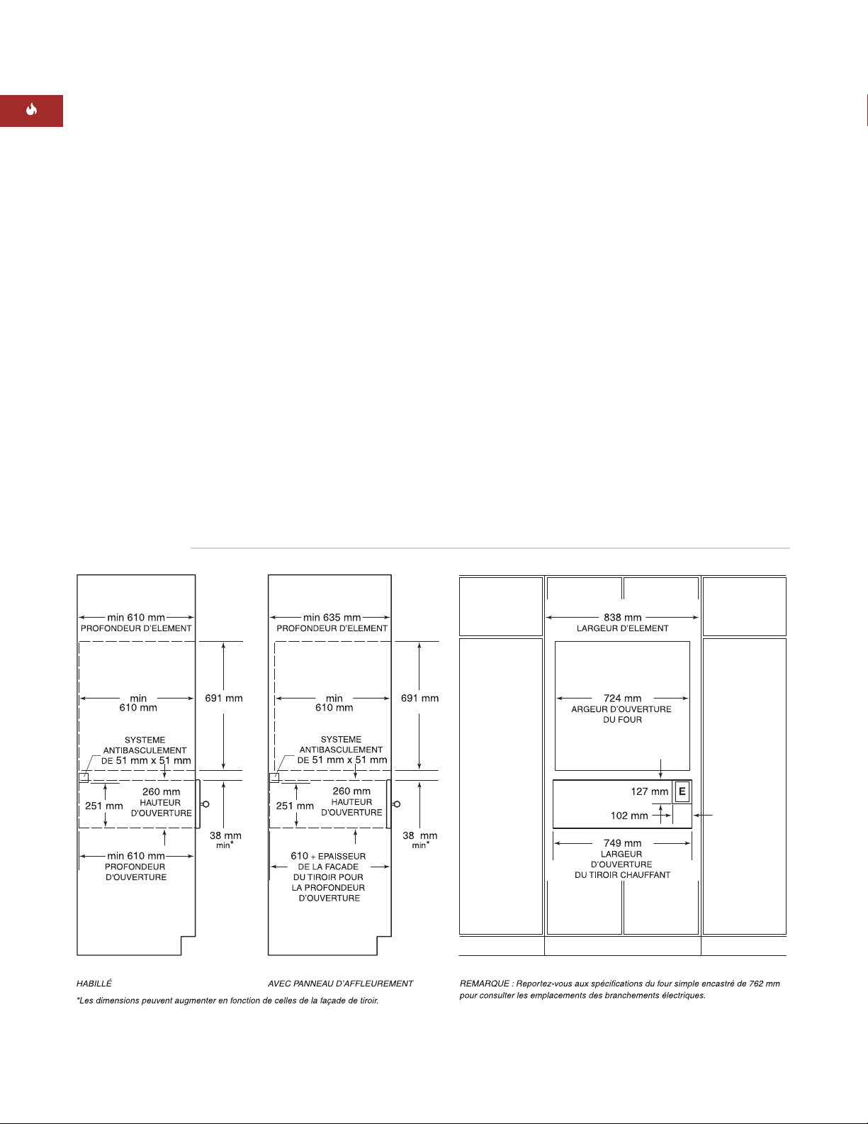
48
TIROIR CHAUFFANT WOLF
REMARQUE IMPORTANTE :
Un espace additionnel peut être requis entre les ouvertures du
tiroir chauffant et du four. Assurez-vous que
les appuis du four n’empiètent pas sur les
dimensions intérieures requises du tiroir
chauffant.
Lorsque le tiroir chauffant est installé audessous d’un four encastré, un minimum de
38 mm doit être prévu entre les ouvertures du
tiroir chauffant et du four pour placer le
système antibasculement et la plate-forme du
four. Lorsque le tiroir chauffant est installé audessus d’un four encastré, il est nécessaire de
prévoir un minimum de 22 mm.
REMARQUE IMPORTANTE :
Dans le cas
d’une installation de façade de tiroir habillable,
vous devrez peut-être augmenter l’espace
requis entre les ouvertures du tiroir chauffant
et du four encastré, en fonction des dimensions du panneau de recouvrement et du
chevauchement.
FACADE DE TIROIR
INTEGREE
INSTALLATION AVEC FOUR
ENCASTRE
Le tiroir chauffant Wolf avec façade intégrée
peut être installé au-dessous ou au-dessus
d’un four encastré simple Wolf de 762 mm ou
de 914 mm, à condition qu’il soit complètement enfermé, haut et bas. Reportez-vous à
l’illustration ci-après. Reportez-vous également
aux instructions d’installation fournies avec le
four encastré pour obtenir des spécifications
supplémentaires. Les dimensions varient selon
le type d’installation.
Le tiroir chauffant Wolf est étudié et approuvé
pour être installé avec des fours encastrés
Wolf.
La plate-forme du tiroir chauffant doit pouvoir
supporter une charge de 91 kg. Un minimum
de 25 mm doit être prévu au-dessus de la
plinthe pour autoriser le chevauchement
de la moulure du tiroir chauffant.
Installation avec un four encastré – façade de tiroir intégrée
Page 49
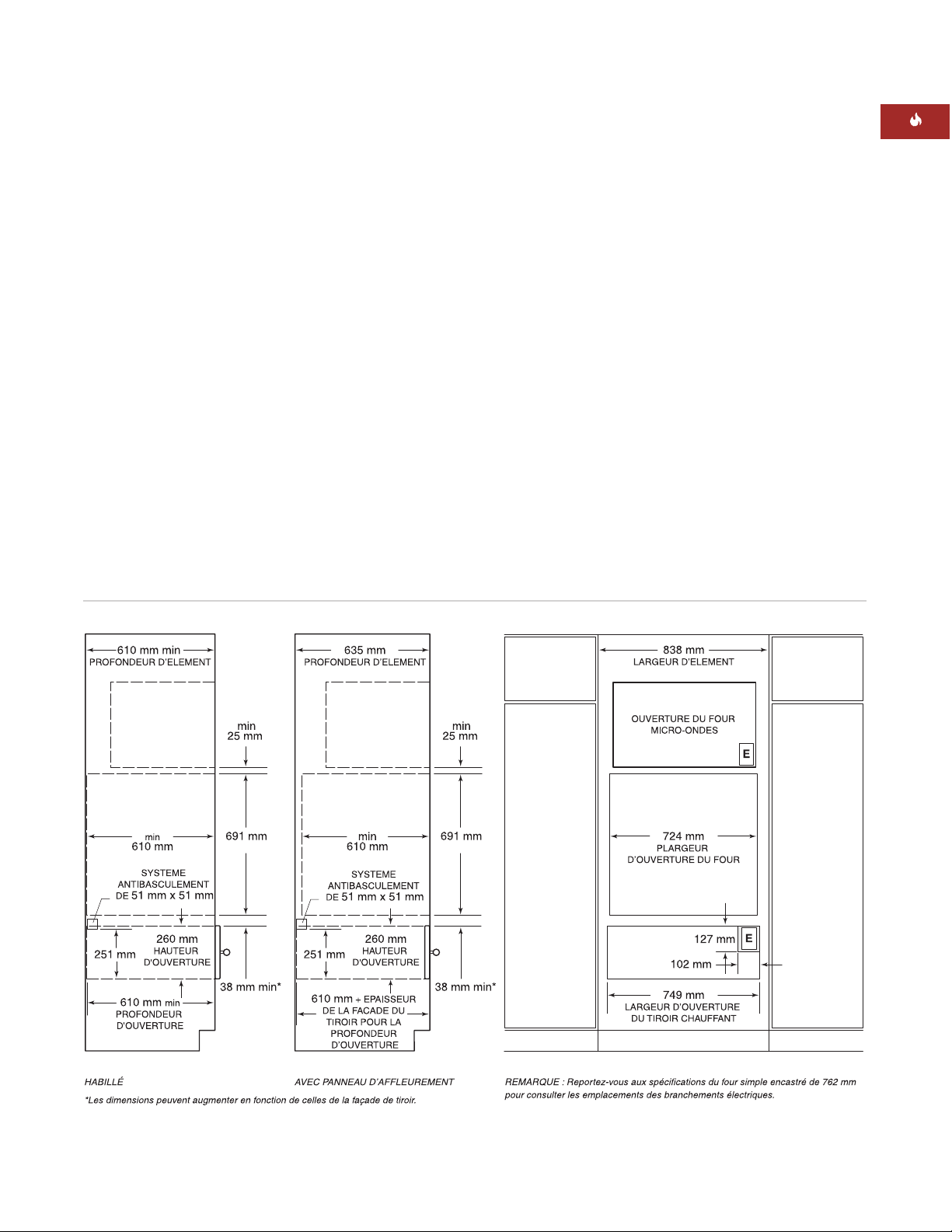
49
INSTRUCTIONS D’INSTALLATION
Installation avec un four et un four micro-ondes encastrés de 762 mm – façade de tiroir intégrée
Reportez-vous aux instructions d’installation
fournies avec le four et le four micro-ondes
encastrés pour obtenir des spécifications
supplémentaires. Les dimensions varient
selon le type d’installation.
Le tiroir chauffant Wolf avec une façade
intégrée peut être installé à côté ou au-dessus
d’un autre tiroir chauffant Wolf, à condition
que chaque appareil soit complètement
enfermé, haut et bas.
FACADE DE TIROIR
INTEGREE
OPTIONS D’INSTALLATION
Le tiroir chauffant Wolf avec une façade
intégrée peut être installé combiné à un four
simple et à un four micro-ondes encastrés
de 762 mm avec une moulure de 762 mm, à
condition qu’il soit complètement enfermé,
haut et bas. Reportez-vous à l’illustration
ci-après.
Le tiroir chauffant Wolf avec une façade
intégrée peut également être installé
combiné à un four simple et à un four
micro-ondes encastrés de 914 mm avec
une moulure de 914 mm.
La plate-forme du tiroir chauffant doit
pouvoir supporter une charge de 91 kg.
Un minimum de 25 mm doit être prévu
au-dessus de la plinthe pour autoriser
le chevauchement de la moulure du
tiroir chauffant.
Page 50

De plus, renseignez-vous sur les ordonnances
et codes locaux lorsque vous installez votre
alimentation électrique.
50
TIROIR CHAUFFANT WOLF
CONFIGURATION ELECTRIQUE
Le tiroir chauffant Wolf exige une alimentation
électrique distincte et mise à la terre de
220 – 240 V c.a. et de 50/60 Hz et doit être
raccordé à un circuit de dérivation individuel
correctement mis à la terre et protégé par un
disjoncteur ou un fusible temporisé de 15 ou
20 A.
REMARQUE IMPORTANTE :
Le tiroir chauffant doit être branché à un cordon électrique
homologué de mise à la terre à 3 broches afin
de minimiser les risques de choc électrique.
Si la prise est située derrière l’appareil,
assurez-vous qu’elle affleure le mur arrière.
Pour repérer la prise électrique, reportez-vous
à l’illustration de votre type d’installation
pages 43 – 49.
Deux tiroirs chauffants installés côte à côte
peuvent utiliser la même prise électrique. Un
disjoncteur de 30 A est requis pour ce type
d’installation.
N’utilisez pas de cordon de rallonge ou
d’adaptateur à deux broches. La mise à la
terre électrique est requise sur cet appareil
ménager. N’enlevez pas la broche de mise
à la terre du cordon électrique.
La prise électrique doit être vérifiée par
un électricien qualifié qui s’assurera
qu’elle est dotée de la polarité adéquate.
Assurez-vous que la prise fournit 220 –
240 V c.a. et qu’elle est correctement
mise à la terre.
REMARQUE
IMPORTANTE
Conformez-vous
aux ordonnances
et aux codes
locaux lorsque
vous installez
votre alimentation
électrique.
Page 51

51
INSTRUCTIONS D’INSTALLATION
APPUIS D’ELEMENT DE CUISINE
REMARQUE IMPORTANTE :
Lorsque le tiroir
chauffant est installé avec un four encastré,
un espace supplémentaire entre les ouvertures
pourrait se révéler nécessaire. Assurez-vous
que les appuis du four n’empiètent pas sur les
dimensions intérieures requises pour le tiroir
chauffant.
Le tiroir chauffant avec une façade en acier
inoxydable peut reposer sur une solide plateforme ou sur des rails de 51 mm x 51 mm ou
de 51 mm x 102 mm. La plate-forme ou les
rails doivent être de niveau, solidement
montés et affleurer le bord inférieur de
l’ouverture. Ils doivent pouvoir supporter une
charge de 91 kg.
Si vous utilisez une façade de tiroir intégrée,
elle doit reposer sur une plate-forme solide de
16 mm. Le plate-forme devra être encastrée et
autoriser le chevauchement du rebord du tiroir
chauffant. Pour plus de détails, reportez-vous à
la page 54. La plate-forme doit être de niveau,
solidement montée et pouvoir supporter une
charge de 91 kg.
REMARQUE IMPORTANTE :
Assurez-vous
que la plate-forme ou les rails sont de niveau.
Il est impossible de mettre le tiroir de niveau
une fois installé.
DEBALLAGE DU TIROIR CHAUFFANT
Déballez le tiroir chauffant sur une surface
plane. Enlevez tous les matériaux d’emballage
et le ruban adhésif de l’intérieur du tiroir
chauffant et jetez-les. Ne jetez pas le paquet
contenant les deux vis à bois requises pour
l’installation.
Page 52
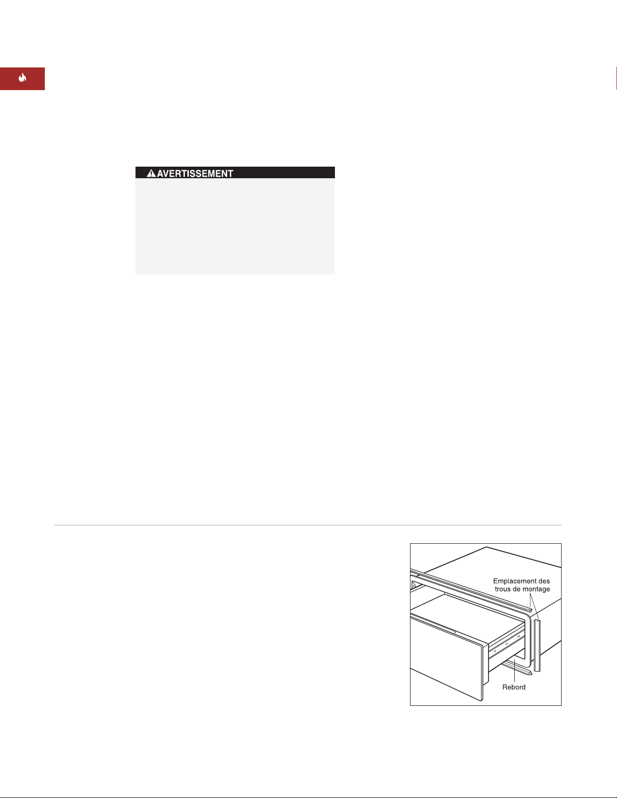
INSTALLATION DE LA MOULURE
DU TIROIR CHAUFFANT
Dégagez la moulure de tous les matériaux
d’emballage. Le kit d’avant de tiroir en
acier inoxydable est fourni avec deux longs
morceaux de moulure pour les rebords
supérieur et inférieur du tiroir chauffant et
deux morceaux de moulure plus courts pour
les côtés. Chaque morceau de moulure est
doté d’une rainure qui s’enclenche sur l’arête
du rebord. Reportez-vous à l’illustration
ci-après.
Placez un des longs morceaux de moulure
sur le rebord supérieur du tiroir chauffant
de sorte que l’encoche ménagée dans la
moulure s’enclenche sur le rebord supérieur.
Ensuite, placez l’un des petits morceaux de
moulure sur l’arête du rebord gauche. La
moulure supérieure et la moulure latérale
devraient s’emboîter. Les trous de montage se
trouvent à l’arrière des morceaux de moulure.
Utilisez les petites vis à bois de 8 mm de long
contenues dans le kit pour fixer ces deux
morceaux ensemble.
Répétez l’opération pour fixer les moulures
inférieure et de droite.
52
TIROIR CHAUFFANT WOLF
FACADE DE TIROIR EN ACIER
INOXYDABLE
INSTALLATION DU SYSTEME
ANTIBASCULEMENT
Installez un système antibasculement de
51 mm x 51 mm ou de 51 mm x 102 mm
contre la paroi arrière de l’élément de cuisine.
Lorsque le tiroir chauffant est installé audessous d’un four encastré, vous pouvez
utiliser une plate-forme de 22 mm d’épaisseur
pour permettre aux moulures du tiroir chauffant et du four de se rejoindre. La plate-forme
servira de dispositif antibasculement au tiroir
chauffant. Ces deux types d’installation sont
illustrés page 44.
Un système ou une plate-forme antibasculement doit être installée pour
empêcher le tiroir chauffant de basculer
vers l’avant lorsque vous l’ouvrez alors
qu’il est chargé. Le non-respect de cette
recommandation peut entraîner des
blessures et des dommages de l’élément
de cuisine.
Installation de la moulure du tiroir
chauffant
Page 53
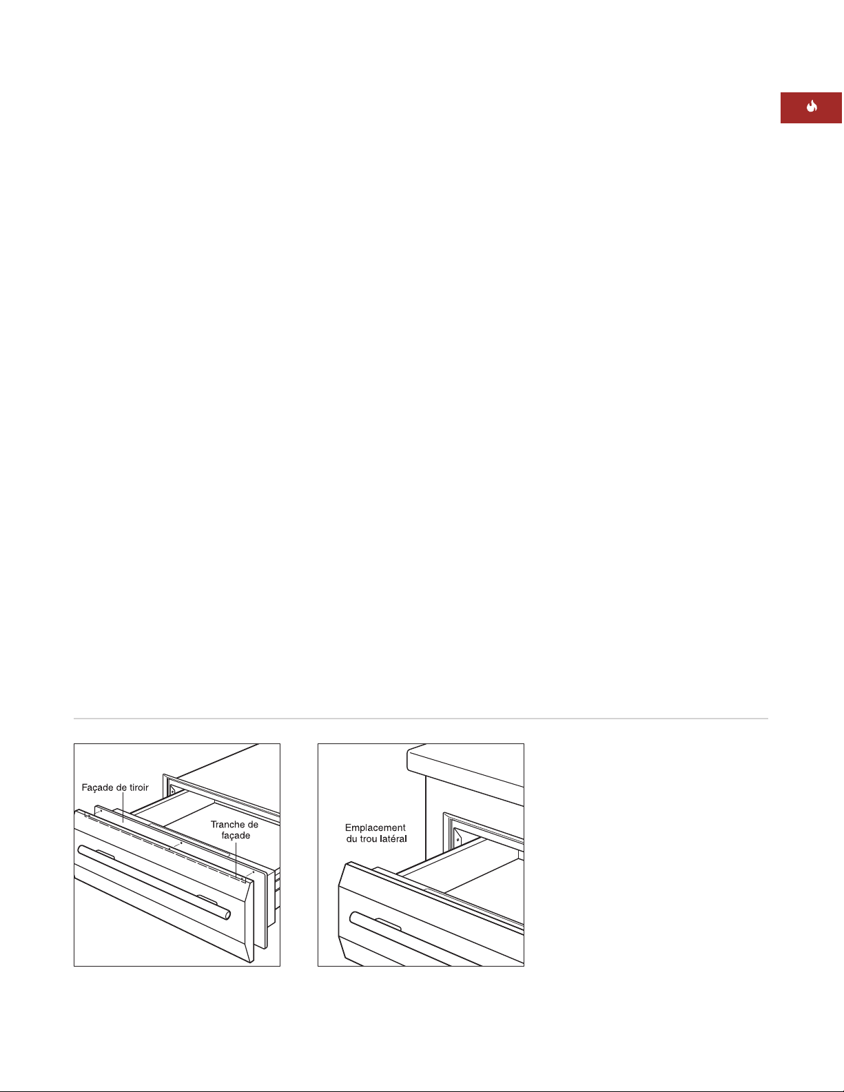
53
INSTRUCTIONS D’INSTALLATION
FACADE DE TIROIR EN ACIER
INOXYDABLE
INSTALLATION DE LA FACADE
Dégagez la poignée et la façade de tous les
matériaux d’emballage. Enlevez avec précaution le revêtement de protection de la façade
en acier inoxydable. Le revêtement adhésif
devrait se décoller proprement de la surface,
mais le cas échéant, tous résidus restants
devraient être enlevés avec un détergent doux.
Pour fixer la poignée à la façade, alignez les
trous des entretoises et de la poignée avec
ceux de la façade. Insérez les vis de la poignée
dans les trous de la façade et serrez-les sur
la façade.
Faites glisser la tranche supérieure de la
façade sur l’avant du tiroir. Insérez trois vis
dans le dessus de la tranche de la façade, par
l’avant du tiroir, et serrez-les. Insérez trois vis
dans le bas de la façade, par l’avant du tiroir,
et serrez-les. Reportez-vous à l’illustration
ci-après.
Coupez le courant à la prise électrique.
INSTALLATION DU TIROIR
CHAUFFANT
Faites glisser le coin gauche du tiroir chauffant
dans l’ouverture. Si la prise électrique est
installée dans l’ouverture, branchez le cordon
dans la prise. Repliez l’excès de cordon
derrière ou à côté de l’appareil. Si la prise est
située dans un élément de cuisine adjacent,
faites passer le cordon électrique par l’orifice
ménagé dans la paroi de l’élément. Repoussez
le tiroir dans l’ouverture jusqu’à ce que la
moulure rejoigne l’avant de l’élément. Assurezvous que le cordon électrique ne se coince pas
sous le tiroir chauffant.
REMARQUE IMPORTANTE :
Ne soulevez pas
la poignée pour pousser le tiroir en place. Vous
risqueriez de rayer le panneau de commande.
Ouvrez complètement le tiroir chauffant.
Percez un avant-trou dans chaque trou latéral
situé vers l’avant, de chaque côté du tiroir
chauffant. Posez les vis à bois fournies avec
l’appareil. Reportez-vous à l’illustration
ci-après.
Rétablissez le courant à la prise électrique.
Installation du tiroir chauffantFixation de la poignée
Page 54
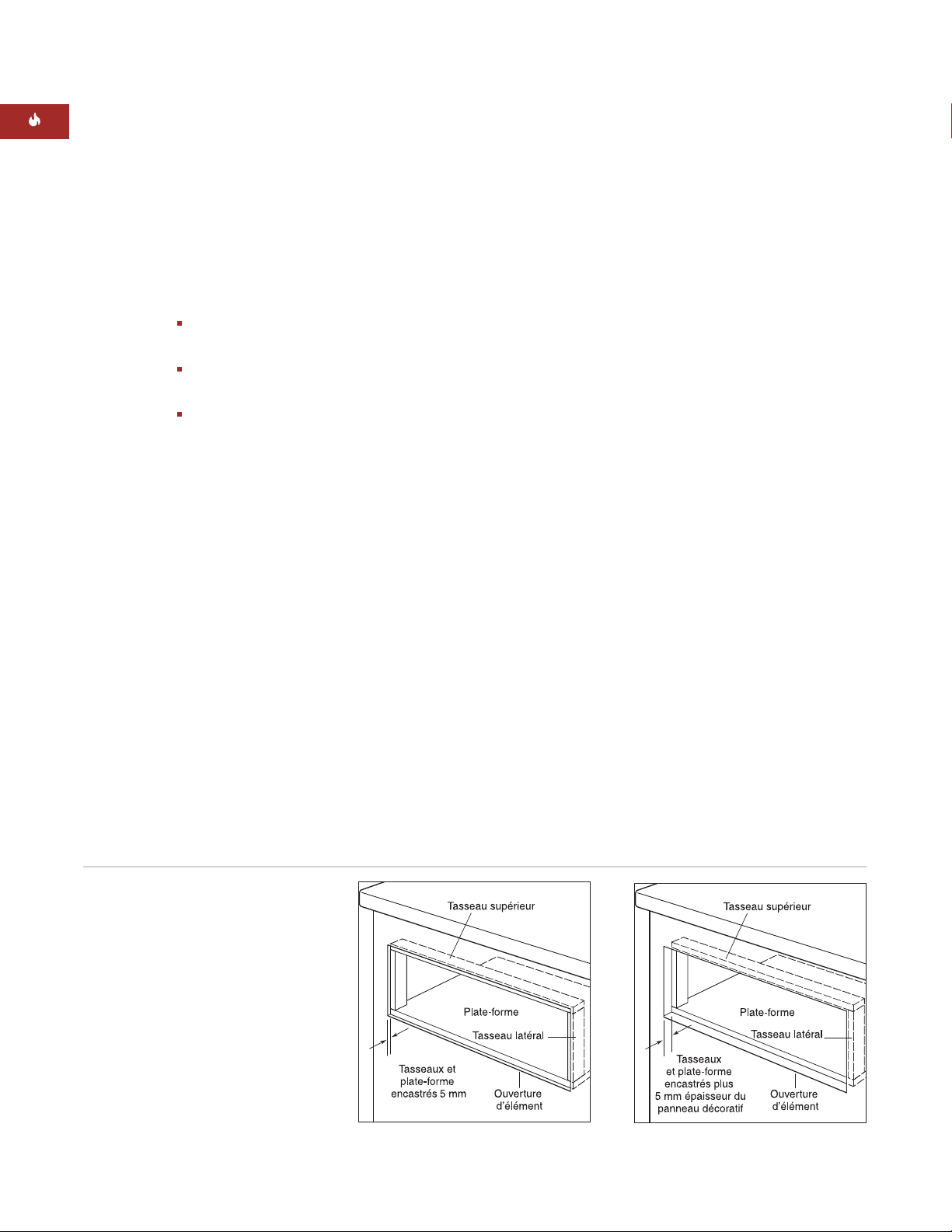
54
FACADE DE TIROIR INTÉGRÉE
INSTALLATION DES TASSEAUX ET DE
LA PLATE-FORME
Pour une installation de tiroir habillé épais ou
d’affleurement, vous devrez installer dans
l’ouverture une plate-forme et des tasseaux
encastrés aux dimensions suivantes :
Dimensions du tasseau supérieur
749 mm L x 13 mm H x 51 mm P
Dimensions des tasseaux latéraux
13 mm L x 232 mm H x 51 mm P
Dimensions de la plate-forme
749 mm L x 16 mm H x 603 mm P
La profondeur de la plate-forme pourrait
augmenter en fonction de la profondeur de
l’élément de cuisine.
Pour une installation de tiroir habillé d’un
panneau épais, la plate-forme et les tasseaux
devront être encastrés selon une profondeur de
5 mm. Pour une installation avec un panneau
d’affleurement, ils devront être encastrés selon
une profondeur de 5 mm plus l’épaisseur du
panneau décoratif du tiroir, afin que le panneau
affleure l’avant de l’élément de cuisine. Assurezvous de monter solidement la plate-forme de
sorte qu’elle puisse supporter une charge
minimale de 91 kg. Reportez-vous aux illustrations
ci-après.
REMARQUE IMPORTANTE : Pour une installation de tiroir habillé d’un panneau épais,
assurez-vous de ne pas encastrer les tasseaux
selon une profondeur de plus de 5 mm. Un
encastrement plus profond pourrait empêcher
le tiroir de se fermer correctement.
TIROIR CHAUFFANT WOLF
REMARQUE IMPORTANTE :
Assurez-vous de
procéder à la finition de la tranche intérieure
de l’ouverture et de l’avant de l’étagère et des
tasseaux. En effet, certaines de ces zones
seront visibles lorsque le tiroir sera ouvert.
REMARQUE IMPORTANTE :
Repérez l’endroit
des trous de montage du cadre du tiroir chauffant afin de vous assurer que les vis utilisées
pour fixer les tasseaux ne bouchent pas les
trous des vis utilisées pour monter le tiroir
chauffant.
Tasseaux et plate-forme encastrés –
installation de tiroir équipé de
panneau d’affleurement
Tasseaux et plate-forme encastrés –
installation de tiroir équipé de panneau
d’habillage
Page 55

55
INSTRUCTIONS D’INSTALLATION
Installation du tiroir chauffant
FACADE DE TIROIR INTÉGRÉE
INSTALLATION DU SYSTEME
ANTIBASCULEMENT
Installez un système antibasculement de
51 mm x 51 mm ou de 51 mm x 102 mm
contre la paroi arrière de l’élément de cuisine
tel qu’illustré pour votre installation spécifique
pages 47 – 49.
INSTALLATION DU TIROIR
CHAUFFANT
Coupez le courant à la prise électrique. Faites
glisser le coin gauche du tiroir chauffant dans
l’ouverture. Si la prise électrique est installée
dans l’ouverture, branchez le cordon dans la
prise. Repliez l’excès de cordon derrière ou à
côté de l’appareil. Si la prise est située dans un
élément de cuisine adjacent, faites passer le
cordon électrique par l’orifice ménagé dans la
paroi de l’élément. Repoussez l’appareil dans
l’ouverture jusqu’à ce que le rebord du tiroir
chauffant se trouve contre les tasseaux et la
plate-forme encastrés. Assurez-vous que le
cordon électrique ne se coince pas sous le
tiroir chauffant.
Ouvrez complètement le tiroir. Percez les
avant-trous dans chaque trou latéral situé
vers l’avant, de chaque côté du tiroir chauffant.
Posez les vis à bois fournies avec le tiroir
chauffant. Reportez-vous à l’illustration
ci-après. Rétablissez le courant à la prise
électrique.
Page 56

56
TIROIR CHAUFFANT WOLF
FACADE DE TIROIR INTÉGRÉE
INSTALLATION DE LA FACADE SUR
LE TIROIR
Débranchez la ligne de communications de la
prise de télécommunications double. Pour retirer
celle-ci, abaissez l'agrafe de retenue de la façade
du panneau de montage, poussez d'abord le côté
de la bague de retenue de la prise à travers le
panneau, puis faites pivoter la prise hors du
panneau de montage. Placez la prise de télécommunications dans le cadre du tiroir.
Placez le panneau de métal de la façade de tiroir
intégrée sur l'arrière du panneau de façade décoratif. Marquez l'emplacement de tous les trous
dans le panneau en métal, sur le panneau décoratif.
Tracez une ligne du bord de chaque trou oblong
jusqu'au trou oblong correspondant au-dessous.
Les marques à l'arrière du panneau décoratif
devraient être similaires à celles de l'illustration
du panneau inférieur ci-après.
Pour chaque trou marqué sur le panneau décoratif (12 emplacements : 6 pour les têtes de vis et
6 pour les arrières des butoirs en caoutchouc),
percez un trou de 12,7 mm et de 6,3 mm de
profondeur à l'arrière du panneau.
Tracez les rectangles (8) marqués à l'arrière du
panneau décoratif de 6,3 mm de profondeur.
Assemblez le kit de fixation de la poignée à
l'avant du panneau décoratif. Le jeu de façade
de tiroir intégrée ne comprend pas de poignée.
Le propriétaire peut ainsi assortir la poignée
aux éléments de cuisine avoisinants.
Au moyen de ces six vis fournies avec le tiroir
chauffant, installez le panneau de métal
contenu dans le kit de façade de tiroir intégrée
sur l'avant du tiroir chauffant. Assurez-vous
que la face brossée du métal est orientée vers
le tiroir chauffant.
Installez les six butoirs de caoutchouc
contenus dans le kit de façade de tiroir chauffant sur le panneau en métal. Fixez le panneau
décoratif au tiroir chauffant en le vissant par
l'arrière du tiroir sur le panneau de façade
décoratif à l'aide des six vis de montage de
12,7 mm contenues dans le kit.
Emplacement des butoirs et des vis
de montage
Vue arrière du panneau décoratif
Page 57

57
INFORMATION
DE CONTACT
Site Internet :
wolfappliance.com
DEPISTAGE DES PANNES
REMARQUE IMPORTANTE :
Si le tiroir chauffant ne fonctionne pas correctement, suivez les
étapes de dépistage des pannes suivantes :
Vérifiez si l’alimentation électrique est
raccordée au tiroir chauffant.
Vérifiez les branchements électriques afin
de vous assurer que l’installation a été
effectuée correctement.
Suivez les procédures de dépistage des
pannes décrites dans le Guide d’utilisation
et d’entretien du tiroir chauffant Wolf.
Si le tiroir chauffant ne fonctionne toujours
pas, contactez votre dépositaire ou votre
distributeur régional Wolf. N’essayez pas de
réparer vous-même le tiroir chauffant.
SERVICE APRES-VENTE
Pour obtenir les coordonnées de votre
service après-vente local, adressez-vous à
votre dépositaire Wolf ou consultez la page
“Locator” de notre site Internet,
wolfappliance.com, pour trouver les coordonnées des distributeurs régionaux par
pays.
Lorsque vous contactez le service aprèsvente, vous devez fournir les numéros de
modèle et de série du tiroir chauffant.
Ces deux numéros figurent sur la plaque
des caractéristiques du produit située sur
la partie avant gauche de la base de
l’élément intérieur. Pour accéder à la
plaque des caractéristiques, vous devez
ouvrir complètement le tiroir. Reportezvous à l’illustration figurant à la page 41.
INSTRUCTIONS D’INSTALLATION
Les informations et les images contenues dans ce
guide sont protégées par des droits d’auteur et
sont la propriété de Wolf Appliance, Inc., une filiale
de Sub-Zero, Inc. Ce guide et les informations et
images qu’il contient ne peuvent être copiés ou
utilisés, en partie ou en totalité, sans l’autorisation
écrite expresse de Wolf Appliance, Inc., filiale de
Sub-Zero, Inc.
© Wolf Appliance, Inc. tous droits réservés
Page 58

Man mano che seguite queste istruzioni,
noterete dei simboli di AVVERTENZA ed
ATTENZIONE. Queste informazioni
evidenziate sono importanti per l’installazione
sicura ed efficiente dell’apparecchiatura Wolf.
Durante l’installazione sarete esposti a due
potenziali pericoli.
Un’altra nota in calce che vorremmo identificare
è NOTA IMPORTANTE: evidenzia informazioni di
particolare importanza per un’installazione
senza problemi.
Segnala una situazione con possibili
lesioni minori o danni al prodotto qualora
non non ci si attenga a queste istruzioni.
Indica un pericolo che potrebbe causare
gravi lesioni o morte, qualora non ci si
attenga alle precauzioni.
WOLF®è un marchio registrato di Wolf Appliance, Inc.
INFORMAZIONI
PER I CONTATTI
Sito Web:
wolfappliance.com
Page 59

Registrare il modello e i numeri di matricola
prima di installare lo scaldavivande. Entrambi i
numeri sono elencati sull’etichetta identificativa del prodotto, situata sulla parte anteriore
sinistra del mobile interno. Per accedere
all’etichetta identificativa occorre aprire
completamente il cassetto. Vedere l’illustrazione che segue.
Numero del modello ICBWWD30
Numero di matricola
59
REQUISITI PER L’INSTALLAZIONE
NOTA IMPORTANTE:
questa installazione deve
essere completata da un tecnico qualificato.
Installatore:
leggere tutte le istruzioni per
l’installazione prima di procedere. Conservare queste istruzioni come riferimento per
l’ispettore locale, quindi lasciarle al proprietario dell’abitazione.
Proprietario dell’abitazione:
leggere e
conservare queste istruzioni come riferimento futuro e verificare di aver letto le
intere informazioni per l’utilizzo e la
manutenzione prima dell’uso.
In caso di domande o problemi con
l’installazione rivolgersi al proprio rivenditore
Wolf. È possibile anche visitare il nostro sito
Web all’indirizzo wolfappliance.com.
NOTA IMPORTANTE:
questo elettrodomestico
deve essere installato in conformità ai codici
locali. All’elettrodomestico devono essere
forniti i valori corretti di tensione, frequenza e
amperaggio da un circuito dedicato collegato a
terra, che è protetto da un interruttore di
circuito di dimensioni appropriate o da un
fusibile ritardato. I valori corretti di tensione,
frequenza e amperaggio sono elencati
sull’etichetta identificativa del prodotto.
CASSETTO SCALDAVIVANDE WOLF
Posizione della piastra dei valori nominali
Posizione
dell’etichetta
identificativa
Modello ICBWWD30
con mascherina
anteriore in acciaio
inossidabile
Modello ICBWWD30
con mascherina
anteriore
integrata
Page 60

60
CASSETTO SCALDAVIVANDE WOLF
OPZIONI MASCHERINA
ANTERIORE
NOTA IMPORTANTE:
il modello
ICBWWD30
va installato con una mascherina anteriore
Wolf in acciaio inossidabile o integrata.
Modello classico in
acciaio inossidabile
WWDFRONT/S
Mascherina anteriore
integrata
WWDFRONT/I
(consente l’inserimento
di pannelli in legno)
Le mascherine anteriori vengono ordinate
e spedite come accessori di vendita ed
includono ulteriori istruzioni per l’installazione.
I modelli in acciaio inossidabile includono
un’impugnatura tubolare dello stesso tipo.
La mascherina anteriore integrata consente
l’inserimento di un pannello in legno su
misura fornito dal cliente. Le impugnature
tubulari in acciaio inossidabile opzionali in
acciaio inossidabile classico sono disponibili
come accessori di vendita.
ATTREZZI E MATERIALE RICHIESTI
Viti per legno o altra bulloneria per
l’installazione della piattaforma piena o di
guide a supporto del cassetto scaldavivande
51 mm x 51 mm o 51 mm x 102 mm di
legno per le guide – devono poter sostenere
un massimo di 91 kg
51 mm x 51 mm o 51 mm x 102 mm di
legno per il blocco antiribaltamento
Sega elettrica
Livello
Trapano e punta da 1,6 mm; per
l’installazione con mascherina anteriore,
occorre anche una punta da 12,7 mm
Cacciavite Phillips
2 viti per legno (in dotazione)
Tacchetti in legno per l’installazione con
mascherina anteriore integrata
ACCESSORI
Gli accessori
opzionali sono
disponibili attraverso il rivenditore
Wolf.
PRIMA DI INIZIARE
Prima di installare il cassetto scaldavivande,
accertarsi di disporre della mascherina Wolf
giusta.
NOTA IMPORTANTE:
se si sta installando
un cassetto scaldavivande con mascherina
anteriore integrata in un’applicazione con
pannello ad inserto, accertarsi che il mobile
sia conforme ai requisiti minimi di 838 mm
di larghezza e 635 mm di profondità per
questa installazione.
Rivolgersi agli enti di servizio locali per
conoscere le norme relative agli impianti
elettrici vigenti nella propria area. Le norme
variano. Installazione, connessioni elettriche
e messa a terra devono essere conformi
alle normative di pertinenza.
Questo elettrodomestico deve avere
un’adeguata messa a terra. Consultare la
sezione Requisiti elettrici a pagina 68.
Accertarsi di disporre degli strumenti e del
materiale necessario per un’adeguata
installazione.
Page 61

61
ISTRUZIONI PER L’INSTALLAZIONE
MODELLO ICBWWD30
con mascherina anteriore in acciaio inossidabile
Larghezza totale 759 mm
Altezza generale 260 mm
Profondità totale 689 mm
Profondità dietro il telaio* 597 mm
Larghezza minima mobile 762 mm
Profondità minima del mobile 610 mm
Supporto base minimo 91 kg
Larghezza incasso 727 mm
Altezza incasso 232 mm
Profondità incasso 606 mm
*Calcolare una profondità aggiuntiva di 10 mm
per lo spessore dei cavi.
MASCHERINA ANTERIORE IN
ACCIAIO INOSSIDABILE
SPECIFICHE PER L’INSTALLAZIONE
Le seguenti illustrazioni indicano le dimensioni
generali e le specifiche per l’installazione del
cassetto scaldavivande Wolf con una mascherina anteriore in acciaio inossidabile.
Wolf consiglia di usare un mobile da 838 mm
di larghezza per il cassetto scandavivande con
mascherina anteriore in acciaio inossidabile.
Occorre un mobile con larghezza minima di
762 mm e profondità minima di 610 mm, con
supporto di base minimo di 91 kg.
Per istruzioni per l’installazione della mascherina anteriore in acciaio inossidabile,
consultare le pagine 70-71. Queste istruzioni
sono in dotazione anche con il kit mascherina
anteriore in acciaio inossidabile.
INSTALLAZIONE SOTTO IL PIANO
DI LAVORO
Per installazioni sotto il piano di lavoro, si
consiglia una distanza di 597 mm dal fondo
dell’incasso al pavimento. Effettuare l’installazione ad una distanza minima di 127 mm dal
pavimento o di 25 mm sopra lo zoccolo.
Il cassetto scaldavivande Wolf con mascherina
anteriore in acciaio inossidabile può essere
installato sotto un piano di cottura elettrico o a
gas, ammesso che sia completamente incassato in senso verticale. Lasciare spazio sufficiente per i collegamenti di gas ed elettrico per
il piano di cottura. Per ulteriori specifiche,
consultare le istruzioni per l’installazione per il
piano di cottura. Le dimensioni variano
secondo l’installazione specifica.
727 mm
LARGHEZZA INCASSO
E
127
102
838 mm
LARGHEZZA MINIMA CONSIGLIATA
PER IL MOBILE min
762 mm
914 mm
ALTEZZA
STANDARD
DAL PAVIMENTO
AL PIANO
DI LAVORO
127 mm
DISTANZA
MINIMA DAL
FONDO INCASSO
AL PAVIMENTO
ALTEZZA INCASSO
DA
232 mm
PROFONDITÀ
INCASSO DA
606 mm minimo
DA
51 mm x 51 mm
LE DIMENSIONI
VARIANO*
TENERE
CONTO DELLA
SOVRAPPOSIZIONE
DEL CASSETTO
SU TUTTI I LATI
16 mm
*Calcolare uno spazio sufficiente per l’inserimento del blocco antiribaltamento e della sovrapposizione del cassetto
PROFONDITÀ
MOBILE DA
610 mm
Dimensioni generali - Mascherina anteriore in acciaio
inossidabile
Installazione sotto il piano di lavoro - Mascherina anteriore in acciaio inossidabile
Page 62

62
CASSETTO SCALDAVIVANDE WOLF
MASCHERINA ANTERIORE
IN ACCIAIO INOSSIDABILE
INSTALLAZIONE CON FORNO
INCASSATO
Il cassetto scaldavivande Wolf con mascherina
anteriore in acciaio inossidabile può essere
installato sotto o sopra un forno singolo Wolf
incassato da 762 mm o sotto un doppio forno,
ammesso che sia completamente incassato in
senso verticale. Vedere l’illustrazione che
segue. Consultare inoltre le istruzioni per
l’installazione in dotazione al forno incassato
per ulteriori specifiche. Le dimensioni variano
secondo l’installazione specifica.
Il cassetto scaldavivande Wolf è concepito ed
approvato per l’installazione con forni incassati
Wolf.
La piattaforma del cassetto deve poter
sostenere un massimo di 91 kg. Calcolare un
minimo di 25 mm sopra lo zoccolo per consentire la sovrapposizione della rifinitura del
cassetto scaldavivande.
Installazione con forno incassato - Mascherina anteriore in acciaio inossidabile
NOTA IMPORTANTE:
potrebbe essere necessario più spazio tra il cassetto scaldavivande e
gli incassi per i forni. Controllare che i supporti
dei forni non ostruiscano le dimensioni interne
richieste per il cassetto scaldavivande.
Se il cassetto scaldavivande viene installato
sotto un forno incassato, calcolare una
distanza minima di 60 mm tra il cassetto scaldavivande e le aperture per il forno, per il
posizionamento del blocco antiribaltamento.
Per garantire un’adeguata corrispondenza tra
la rifinitura del cassetto scaldavivande e quella
del forno incassato, occorre usare una
piattaforma da 22 mm per separare le due
aperture. Questo funge da piattaforma di
supporto per il forno e da dispositivo antiribaltamento per il cassetto scandavivande.
Entrambi i tipi di installazione sono indicati
nell’illustrazione che segue.
NOTA IMPORTANTE:
se il cassetto scaldavivande viene installato sopra un forno incassato, occorre disporre di una piattaforma da
22 mm per garantire lo spazio necessario per
la sovrapposizione.
Page 63

63
ISTRUZIONI PER L’INSTALLAZIONE
Installazione con forno incassato e forno a microonde - Mascherina anteriore in acciaio inossidabile
INSTALLAZIONI OPZIONALI
Il cassetto scaldavivande Wolf con mascherina
anteriore in acciaio inossidabile può essere
installato in combinazione con un forno
singolo da 762 mm ed un forno a microonde
con rifinitura da 762 mm, ammesso che il
cassetto scandavivande sia completamente
incassato in senso verticale. Vedere l’illustrazione che segue. Consultare inoltre le
istruzioni per l’installazione in dotazione al
forno incassato ed al forno a microonde per
ulteriori specifiche. Le dimensioni variano
secondo l’installazione specifica.
La piattaforma del cassetto deve poter
sostenere un massimo di 91 kg. Calcolare un
minimo di 25 mm sopra lo zoccolo per consentire la sovrapposizione della rifinitura del
cassetto scaldavivande.
Il cassetto scaldavivande Wolf con mascherina
anteriore in acciaio inossidabile può essere
installato accanto o sopra un altro cassetto
scaldavivande Wolf, ammesso che tutte le
unità siano completamente incassate in senso
verticale.
Installazione con forno incassato - Mascherina
anteriore in acciaio inossidabile
MASCHERINA ANTERIORE
IN ACCIAIO INOSSIDABILE
INCASSO FORNO
63,5 mm x
63,5 mm
BLOCCO
ANTIRIBAL-
TAMENTO
273 mm
LA GUARNIZIONE DEL
FORNO FUORIESCE SOTTO
LA PIATTAFORMA
19 mm PIATTAFORMA DI
SUPPORTO FORNO CON
PARETE SPESSA
INCASSO
CASSETTO
SCALDAVIVANDE
600 mm
VISTA LATERALE
GUIDA ESTERNA
232 mm
3 mm
16 mm
16 mm
41 mm
SEZIONE
ESPOSTA
60
mm
260 mm
PARTE
ANTERIORE
Page 64

64
CASSETTO SCALDAVIVANDE WOLF
MODELLO ICBWWD30
con mascherina anteriore integrata
Larghezza totale 746 mm
Altezza generale 257 mm
Profondità generale* (dietro il telaio) 597 mm
Requisiti minimi per il mobile
Sovrapposizione 838 mm L x 610 mm P
Inserto 838 mm L x 635 mm P
Supporto base minimo 91 kg
Larghezza incasso 749 mm
Altezza incasso 260 mm
Profondità incasso** 610 mm
Dimensioni minime pannello
Sovrapposizione 762 mm L x 264 mm A
Inserto 746 mm L x 257 mm A
Spessore minimo pannello 16 mm
Peso massimo pannello 11 kg
*Calcolare una profondità aggiuntiva di 10 mm
per lo spessore dei cavi.
**Per installazioni con inserto, aggiungere lo
spessore della parte anteriore del cassetto alla
profondità dell’incasso.
Dimensioni generali - Mascherina anteriore integrata
Mascherina anteriore integrata - Sovrapposizione
MASCHERINA ANTERIORE
INTEGRATA
SPECIFICHE PER L’INSTALLAZIONE
Le seguenti illustrazioni indicano le dimensioni
generali e le specifiche per l’installazione del
cassetto scaldavivande Wolf con una mascherina anteriore integrata. Il cassetto scaldavivande con mascherina anteriore integrata può
essere usato in applicazioni sovrapposte o con
pannelli ad inserto, dove risulta completamente incassato nel mobile.
Tenere a mente che le dimensioni del pannello
su misura per il cassetto scaldavivande con
mascherina anteriore integrata variano
secondo l’installazione specifica. La tabella che
segue indica le dimensioni minime per installazioni con sovrapposizione o pannello ad
inserto.
Per istruzioni per l’installazione della mascherina anteriore integrata, consultare le pagine
72-74. Queste istruzioni sono in dotazione
anche con il kit mascherina anteriore integrata.
Page 65
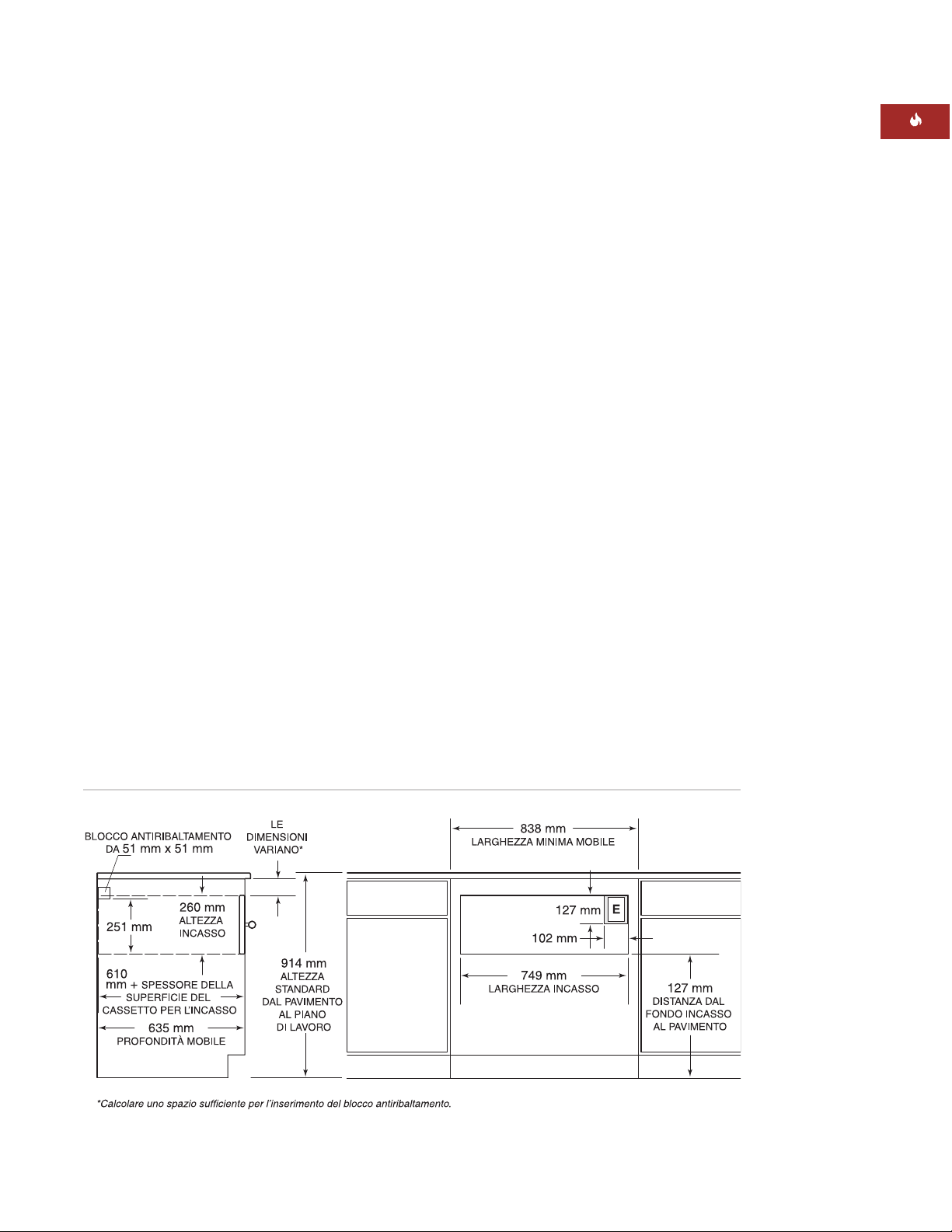
65
ISTRUZIONI PER L’INSTALLAZIONE
Mascherina anteriore integrata - Inserto
MASCHERINA ANTERIORE
INTEGRATA
INSTALLAZIONE A SOVRAPPOSIZIONE
Per l’installazione a sovrapposizione di un
cassetto scaldavivande con mascherina anteriore integrata occorre un mobile con 838 mm
di larghezza minima e 610 mm di profondità
minima. Occorre un supporto base minimo di
91 kg. Vedere l’lustrazione a pagina 64.
INSTALLAZIONE AD INSERTO
NOTA IMPORTANTE:
l’installazione ad inserto
richiede l’incasso nel mobile del cassetto scaldavivande. Per fare in modo che la mascherina
anteriore sia a filo con il mobile, occorre un
mobile con profondità minima di 635 mm.
Per l’installazione di un cassetto scaldavivande
con mascherina anteriore integrata e pannello
ad inserto occorre un mobile con larghezza
minima di 838 mm e profondità minima di
635 mm. Occorre un supporto base minimo di
91 kg. Vedere l’illustrazione che segue.
INSTALLAZIONE SOTTO IL PIANO
DI LAVORO
Per installazioni sotto il piano di lavoro, si
consiglia una distanza di 597 mm dal fondo
dell’incasso al pavimento. Effettuare
l’installazione ad una distanza minima di
127 mm dal pavimento o di 25 mm sopra lo
zoccolo.
Il cassetto scaldavivande Wolf con mascherina
anteriore integrata può essere installato sotto
un piano di cottura elettrico o a gas da
762 mm o 914 mm, ammesso che sia completamente incassato in senso verticale. Per ulteriori specifiche, consultare le istruzioni per
l’installazione per il piano di cottura. Le dimensioni variano secondo l’installazione specifica.
Page 66

66
CASSETTO SCALDAVIVANDE WOLF
NOTA IMPORTANTE:
potrebbe essere necessario più spazio tra il cassetto scaldavivande e
gli incassi per i forni. Controllare che i supporti
dei forni non ostruiscano le dimensioni interne
richieste per il cassetto scaldavivande.
Se il cassetto scaldavivande viene installato
sotto un forno incassato, calcolare una
distanza minima di 38 mm tra il cassetto scaldavivande e le aperture per il forno, per il
posizionamento del blocco antiribaltamento
e della piattaforma per il forno. Per
l’installazione sopra un forno incassato,
occorre una distanza minima di 22 mm.
NOTA IMPORTANTE:
per un’installazione a
sovrapposizione, occorre aumentare lo spazio
tra il cassetto scaldavivande e le aperture per i
forni ad incasso, secondo le dimensioni del
pannello a sovrapposizione ed il livello di
sovrapposizione.
MASCHERINA ANTERIORE
INTEGRATA
INSTALLAZIONE CON FORNO
INCASSATO
Il cassetto scaldavivande Wolf con mascherina
anteriore integrata può essere installato sotto
o sopra un piano di cottura elettrico o a gas
Wolf da 762 mm o 914 mm, ammesso che sia
completamente incassato in senso verticale.
Vedere l’illustrazione qui sotto. Consultare
inoltre le istruzioni per l’installazione in
dotazione al forno incassato per ulteriori
specifiche. Le dimensioni variano secondo
l’installazione specifica.
Il cassetto scaldavivande Wolf è concepito ed
approvato per l’installazione con forni incassati
Wolf.
La piattaforma del cassetto deve poter
sostenere un massimo di 91 kg. Calcolare un
minimo di 25 mm sopra lo zoccolo per consentire la sovrapposizione della rifinitura del
cassetto scaldavivande.
Installazione con forno incassato - Mascherina anteriore integrata
Page 67

67
ISTRUZIONI PER L’INSTALLAZIONE
Installazione con forno incassato da 762 mm e forno a microonde – Mascherina anteriore integrata
Consultare inoltre le istruzioni per
l’installazione in dotazione al forno incassato
ed al forno a microonde per ulteriori specifiche. Le dimensioni variano secondo
l’installazione specifica.
Il cassetto scaldavivande Wolf con mascherina
anteriore integrata può essere installato
accanto o sopra un altro cassetto scaldavivande Wolf, ammesso che tutte le unità siano
completamente incassate in senso verticale.
MASCHERINA ANTERIORE
INTEGRATA
OPZIONI PER L’INSTALLAZIONE
Il cassetto scaldavivande Wolf con mascherina
anteriore integrata può essere installato in
combinazione con un forno singolo da 762 mm
ed un forno a microonde con rifinitura da 762
mm, ammesso che il cassetto scandavivande
sia completamente incassato in senso verticale. Vedere l’illustrazione che segue.
Il cassetto scaldavivande Wolf con mascherina
anteriore integrata può essere installato anche
in combinazione con un forno incassato
singolo da 914 mm ed un forno a microonde
con rifinitura da 914 mm.
La piattaforma del cassetto deve poter
sostenere un massimo di 91 kg. Calcolare un
minimo di 25 mm sopra lo zoccolo per consentire la sovrapposizione della rifinitura del
cassetto scaldavivande.
Page 68
Durante l’installazione, prestare inoltre attenzione a norme ed ordinanze locali.
68
CASSETTO SCALDAVIVANDE WOLF
REQUISITI ELETTRICI
Il cassetto scaldavivande Wolf richiede una
presa di corrente dedicata da 220–240 V c.a.,
50/60 Hz protetta da un interruttore automatico
da 15 o 20 amp o fusibile ritardato.
NOTA IMPORTANTE:
il cassetto scaldavivande va collegato ad un cavo elettrico con
messa a terra a 3 poli per ridurre al minimo la
possibilità di folgorazione.
Se la presa elettrica è situata dietro l’unità,
accertarsi che sia a filo con la parete posteriore. Per la posizione della presa elettrica,
consultare l’illustrazione per l’installazione
specifica a pagine 61–67.
Per l’installazione affiancata di due cassetti
scaldavivande è possibile collegarsi alla stessa
presa elettrica. Per questa installazione occorre
un interruttore automatico da 30 ampere.
Non usare prolunghe o riduttori a due poli.
Questo elettrodomestico richiede la messa
a terra. Non rimuovere il polo di messa a
terra del cavo di alimentazione.
La presa di corrente va controllata da un
elettricista qualificato per accertarsi che
sia collegata con la polarità giusta.
Controllare che la presa sia da 220–240 V
c.a. con adeguata messa a terra.
NOTA
IMPORTANTE
Nell’installazione
del servizio è
necessario
rispettare tutte le
norme e le ordinanze locali.
Page 69

69
ISTRUZIONI PER L’INSTALLAZIONE
SUPPORTI PER IL MOBILE
NOTA IMPORTANTE:
se il cassetto scaldavivande viene installato con un forno incassato,
occorre calcolare più spazio tra gli incassi.
Controllare che i supporti dei forni non ostruiscano le dimensioni interne richieste per il
cassetto scaldavivande.
Il cassetto scaldavivande con mascherina anteriore in acciaio inossidabile può essere supportato da una piattaforma piena, da guide da
51 mm x 51 mm o da guide da 51 mm x
102 mm. La piattaforma o le guide devono
essere a livello, fissate bene ed a filo con il
bordo inferiore dell’incasso. Devono inoltre
essere in grado di sostenere 91 kg.
Se si fa uso di una mascherina anteriore integrata, questa va sostenuta da una piattaforma
piena da 16 mm. La piattaforma deve essere
incassata e prevedere una sovrapposizione del
collare del cassetto scaldavivande. Per ulteriori
dettagli in merito, consultare pagina 72. La
piattaforma deve essere a livello, ben fissata
ed in grado di sostenere 91 kg.
NOTA IMPORTANTE:
accertarsi che la
piattaforma o le guide siano a livello. Non
esiste un modo per livellare il cassetto scaldavivande una volta installato.
DISIMBALLAGGIO DEL CASSETTO
SCALDAVIVANDE
Disimballare il cassetto scaldavivande su una
superficie piatta. Togliere tutto il materiale di
imballaggio ed il nastro dall’interno del
cassetto scaldavivande e gettarlo. Non gettare
la confezione contenente le due viti per legno
necessarie per l’installazione.
Page 70

INSTALLAZIONE DELLA RIFINITURA
DEL CASSETTO SCALDAVIVANDE
Togliere tutto il materiale di imballaggio dalla
rifinitura. La mascherina anteriore in acciaio
inossidabile dispone di due lunghe rifiniture
per il collare superiore ed inferiore del cassetto
scaldavivande e di due rifiniture corte per i lati.
Ciascuna rifinitura riporta una scanalatura che
poggia sul bordo del collare. Vedere
l’illustrazione che segue.
Poggiare una delle rifiniture lunghe sul collare
superiore del cassetto scaldavivande, per fare
in modo che la scanalatura nella rifinitura
poggi esattamente sul collare superiore.
Poggiare quindi una delle rifiniture corte sul
bordo del collare sinistro. La rifinitura superiore e quella laterale devono incastrarsi. Sul
lato posteriore delle rifiniture vi sono dei fori
di montaggio. Usare le viti lunghe da 8 mm in
dotazione al kit per fissare insieme questi due
pezzi.
Ripetere la procedura per fissare il bordo
destro alla rifinitura inferiore.
70
CASSETTO SCALDAVIVANDE WOLF
MASCHERINA ANTERIORE
IN ACCIAIO INOSSIDABILE
INSTALLAZIONE DEL BLOCCO
ANTIRIBALTAMENTO
Installare un blocco antiribaltamento da
51 mm x 51 mm o 51 mm x 102 mm contro
la parete posteriore del mobile. Se il cassetto
scaldavivande viene installato sotto un forno
incassato, è possibile usare una piattaforma
con spessore da 22 mm per favorire la
corrispondenza tra la rifinitura del cassetto
e quella del forno. La piattaforma agisce da
dispositivo antiribaltamento per il cassetto
scaldavivande. Entrambi i tipi di installazione
sono riportati nelle illustrazioni a pagina 62.
Installare un blocco antiribaltamento o
una piattaforma per impedire il ribaltamento in avanti del cassetto scaldavivande quando viene aperto per riporvi
del cibo. La mancata osservanza di
questa precauzione potrebbe causare
danni a persone o danni al mobile.
Installare la rifinitura del cassetto
scaldavivande
Page 71

71
ISTRUZIONI PER L’INSTALLAZIONE
MASCHERINA ANTERIORE
IN ACCIAIO INOSSIDABILE
INSTALLAZIONE DEL PANNELLO
ANTERIORE
Rimuovere tutto il materiale di imballaggio
dall’impugnatura e dal pannello anteriore.
Rimuovere con delicatezza la copertura protettiva dal pannello anteriore in acciaio inossidabile. La copertura adesiva dovrebbe staccarsi dalla superficie senza difficoltà; eliminare
eventuali residui con un detergente neutro.
Per fissare la maniglia al pannello anteriore,
allineare i fori nei distanziali e nell’impugnatura con i fori sul pannello anteriore.
Inserire le viti della maniglia nei fori nel
pannello anteriore e serrare le viti al pannello
anteriore.
Far scorrere la copertura superiore del
pannello anteriore sulla mascherina. Inserire
tre viti nella sommità del bordo del pannello
anteriore attraverso la mascherina del cassetto
e serrare le viti. Inserire tre viti al fondo del
pannello anteriore attraverso la mascherina del
cassetto e serrare le viti. Vedere l’illustrazione
che segue.
Togliere corrente dalla presa elettrica.
INSTALLAZIONE DEL CASSETTO
SCALDAVIVANDE
Far scorrere l’angolo sinistro del cassetto scaldavivande nell’incasso. Se la presa elettrica è
installata all’interno dell’incasso, collegare il
cavo di alimentazione alla presa. Raccogliere il
cavo in eccesso dietro o di fianco l’unità. Se la
presa si trova in un mobile adiacente, far
passare il cavo di alimentazione attraverso il
foro nella parete del mobile. Spingere il
cassetto nell’incasso fin quando la rifinitura
arriva a toccare la parte anteriore del mobile.
Accertarsi che il cavo di alimentazione non
resti incastrato sotto il cassetto scaldavivande.
NOTA IMPORTANTE:
non usare l’impugnatura per spingere il cassetto in posizione,
onde evitare di graffiare il pannello di
controllo.
Aprire completamente il cassetto scaldavivande. Praticare dei fori pilota nei fori laterali,
situati davanti di lato sul cassetto scaldavivande. Installare le viti per legno in dotazione
all’unità. Vedere l’illustrazione che segue.
Ridare corrente alla presa elettrica.
Installazione del cassetto scaldavivandeFissare la maniglia
Page 72
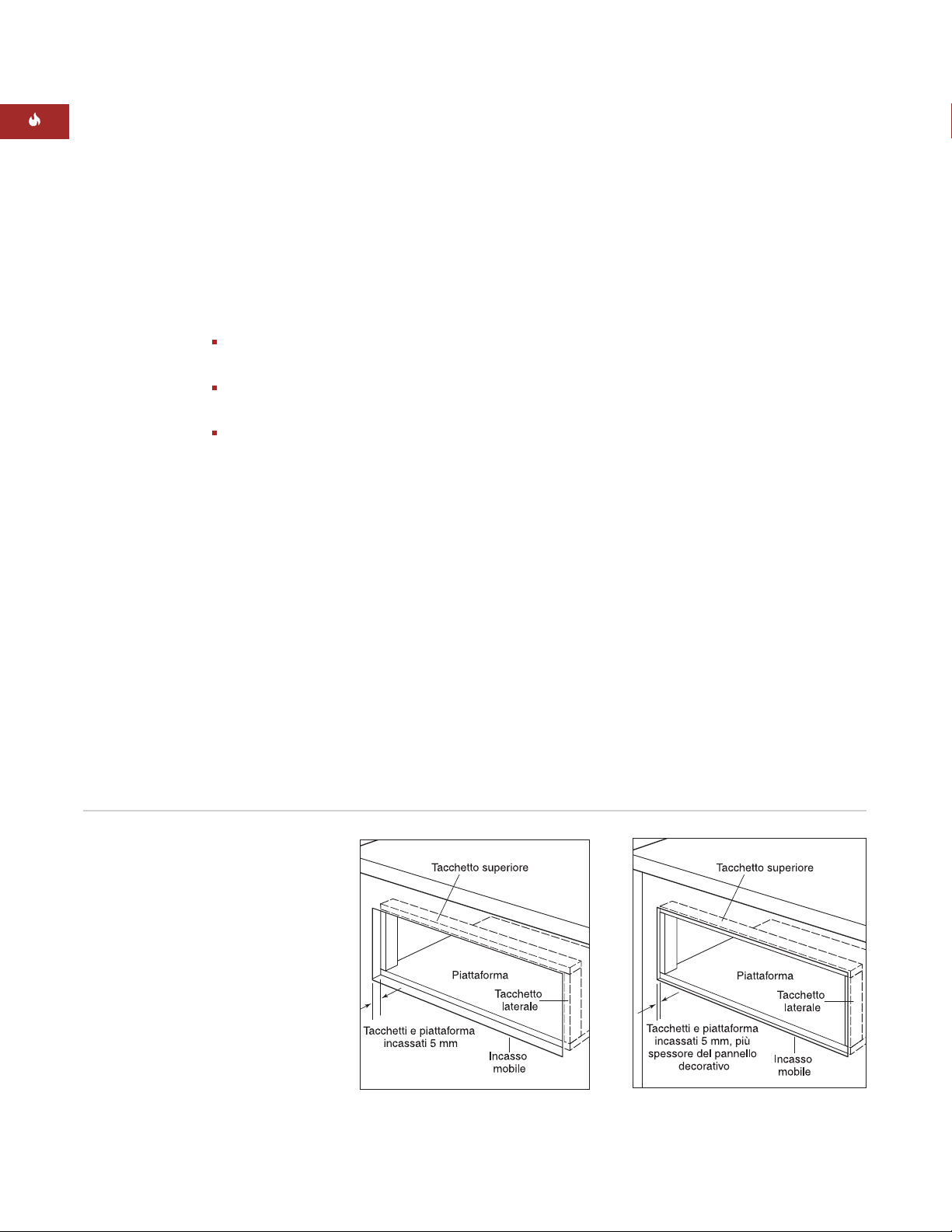
72
PANNELLO ANTERIORE
INTEGRATO
INSTALLAZIONE DI TACCHETTI
E PI AT TAF OR MA
Per l’installazione a sovrapposizione o a
inserto occorre installare nell’incasso una
piattaforma incassata e tacchetti delle seguenti
dimensioni.
Dimensioni tacchetto superiore
749 mm L x 13 mm A x 51 mm P
Dimensioni tacchetto laterale
13 mm L x 232 mm A x 51 mm P
Dimensioni piattaforma
749 mm L x 16 mm A x 603 mm P
La profondità della piattaforma potrebbe
aumentare secondo la profondità del
mobile.
Per l’installazione a sovrapposizione, la
piattaforma ed i tacchetti vanno incassati di
5 mm. Per l’installazione ad inserto, questi
vanno incassati di 5 mm più lo spessore del
cassetto scaldavivande decorativo, consentendo il posizionamento a filo del pannello con
la parte anteriore del mobile. Accertarsi di
fissare bene la piattaforma di modo che possa
sostenere un minimo di 91 kg. Vedere l’illustrazione che segue.
NOTA IMPORTANTE:
in un’installazione a
sovrapposizione, accertarsi di incassare i
tacchetti di non oltre 5 mm. Un incasso più
profondo potrebbe causare problemi con la
CASSETTO SCALDAVIVANDE WOLF
NOTA IMPORTANTE:
accertarsi di finire il
bordo interno dell’incasso e la mascherina
anteriore della mensola e dei tacchetti. Alcune
di queste aree saranno visibili con il cassetto
aperto.
NOTA IMPORTANTE:
controllare la posizione
dei fori di montaggio sul telaio del cassetto
scaldavivande per accertarsi che le viti usate
per fissare i tacchetti non interferiscano con i
fori delle viti per il montaggio del cassetto
scaldavivande.
Tacchetti e piattaforma incassati –
installazione ad inserto
Tacchetti e piattaforma incassati –
installazione a sovrapposizione
Page 73

73
ISTRUZIONI PER L’INSTALLAZIONE
Installazione del cassetto scaldavivande
PANNELLO ANTERIORE
INTEGRATO
INSTALLAZIONE DEL BLOCCO
ANTIRIBALTAMENTO
Installare un blocco antiribaltamento da
51 mm x 51 mm o 51 mm x 102 mm contro la
parete posteriore del mobile nell’illustrazione
dell’installazione specifica a pagine 65-67.
INSTALLAZIONE DEL CASSETTO
SCALDAVIVANDE
Togliere corrente dalla presa elettrica. Far
scorrere l’angolo sinistro del cassetto scaldavivande nell’incasso. Se la presa elettrica è
installata all’interno dell’incasso, collegare il
cavo di alimentazione alla presa. Raccogliere il
cavo in eccesso dietro o di fianco l’unità. Se la
presa si trova in un mobile adiacente, far
passare il cavo di alimentazione attraverso il
foro nella parete del mobile. Spingere l’unità
nell’incasso fin quando il collare del cassetto
scaldavivande non arriva a toccare i tacchetti e
la piattaforma incassati. Accertarsi che il cavo
di alimentazione non resti incastrato sotto il
cassetto scaldavivande.
Aprire completamente il cassetto. Praticare dei
fori pilota nei fori laterali, situati davanti
di lato sul cassetto scaldavivande. Installare le
viti per legno in dotazione al cassetto scaldavivande. Vedere l’illustrazione che segue. Ridare
corrente alla presa elettrica.
Page 74

74
CASSETTO SCALDAVIVANDE WOLF
PANNELLO ANTERIORE
INTEGRATO
INSTALLAZIONE DEL PANNELLO
ANTERIORE SUL CASSETTO
Scollegare le linee di comunicazione dal jack
di comunicazione. Il jack di comunicazione
viene rimosso premendo la pinza di tenuta
sulla parte anteriore del pannello di montaggio e spingendo il lato della pinza del jack
dapprima attraverso il pannello di montaggio e quindi facendo ruotare il jack ed
estraendolo dal pannello di montaggio.
Inserire il jack di comunicazione rimosso
all'interno del telaio del cassetto.
Inserire il pannello metallico dalla mascherina integrata sul retro del pannello decorativo anteriore. Tracciare i fori nel pannello
metallico sul pannello decorativo.
Tracciare una riga dal bordo dei fori
oblunghi al foro corrispondente sottostante.
I contrassegni sul retro del pannello decorativo devono avere lo stesso aspetto di quelli
nell'illustrazione del pannello inferiore.
Per ogni contrassegno rotondo sul pannello
decorativo (12 punti, sei per le viti e sei per
la parte posteriore dei gommini), praticare
un foro da 12,7 mm e profondo 6,3 mm sul
retro del pannello.
Disporre le aree rettangolari (8 punti)
contrassegnate sul retro del pannello decorativo profondo 6,3 mm.
Fissare la bulloneria della maniglia sulla parte
anteriore del pannello decorativo. La mascherina anteriore integrata non include una
maniglia. Questo consente all'utente di garantire un'adeguata corrispondenza della bulloneria della maniglia con quella del mobile.
Usando le sei viti in dotazione al cassetto scaldavivande, installare il pannello metallico dalla
mascherina anteriore integrata sulla mascherina del cassetto scaldavivande. Accertarsi che
il lato spazzolato del pannello metallico sia
rivolto verso il cassetto scaldavivande.
Installare i sei gommini, in dotazione alla
mascherina anteriore, sul pannello metallico.
Fissare il pannello decorativo al cassetto scaldavivande facendo passare le viti attraverso
la parte posteriore del cassetto scaldavivande
nella mascherina decorativa usando le sei
viti di tenuta da 12,7 mm in dotazione al kit.
Posizione dei paraurti e delle viti
di montaggio
Vista posteriore del pannello decorativo
Page 75

75
INFORMAZIONI
PER I CONTATTI
Sito Web:
wolfappliance.com
SOLUZIONE DEI PROBLEMI
NOTA IMPORTANTE:
se il cassetto scaldavivande non funziona correttamente, seguire
questi passaggi per la risoluzione dei problemi:
Verificare che al cassetto scaldavivande
arrivi alimentazione.
Controllare le connessioni elettriche per
accertarsi che l’installazione sia stata
completata correttamente.
Consultare la Guida alla soluzione dei
problemi Wolf nelle informazioni per l’uso e
la manutenzione dei cassetti scaldavivande
Wolf.
Se il cassetto scaldavivande continua a non
funzionare, rivolgersi al proprio rivenditore
o distributore di zona Wolf. Non tentare di
riparare da soli il cassetto scaldavivande.
SE È NECESSARIA ASSISTENZA
Per l’assistenza in zona, rivolgersi al proprio
rivenditore Wolf o visitare la pagina di ricerca
del nostro sito Web,
wolfappliance.com
, per
trovare i distributori di zona in base al Paese.
Prima di chiamare per assistenza, individuare i numeri di modello e di matricola del
cassetto scaldavivande. Entrambi i numeri
sono elencati sull’etichetta identificativa del
prodotto, situata sulla parte anteriore
sinistra del mobile interno. Per accedere
all’etichetta identificativa occorre aprire
completamente il cassetto. Fare riferimento
all’illustrazione a pagina 59.
ISTRUZIONI PER L’INSTALLAZIONE
Le informazioni e le immagini sono protette
da copyright della Wolf Appliance, Inc., una
consociata della Sub-Zero, Inc. Questo documento
e le informazioni o immagini qui contenute non
potranno essere copiati o usati, in parte o nella
loro interezza, senza l’esplicito consenso scritto
della Wolf Appliance, Inc., una consociata della
Sub-Zero, Inc.
©Wolf Appliance, Inc. Tutti i diritti riservati.
Page 76

In diesen Anweisungen sind Symbole für
ACHTUNG und VORSICHT enthalten. Diese
Informationsblöcke sind wichtig für die sichere
und effiziente Installation von Wolf-Geräten.
Es gibt zwei Arten möglicher Gefahren, die
während der Installation auftreten können.
Eine weitere Fußnote, auf die wir aufmerksam
machen möchten, ist ein WICHTIGER HINWEIS:
Er hebt Informationen hervor, die für eine problemlose Installation besonders relevant sind.
VORSICHT
weist auf eine Situation hin, in der
geringfügige Verletzungen oder Produktschäden auftreten, wenn Sie die Anweisungen nicht befolgen.
ACHTUNG
benennt eine Gefahr, die zu einer ernsthaften
Verletzung oder zum Tod führen kann, wenn
die Vorsichtsmaßnahmen nicht eingehalten
werden.
WOLF®ist eine eingetragene Marke von Wolf Appliance, Inc.
KON TAK TINFORMATIONEN
Website:
wolfappliance.com
Page 77

Zeichnen Sie Modell- und Seriennummer auf,
bevor die Wärmeschublade eingebaut wird. Beide
Nummern sind auf dem Produkttypenschild
aufgeführt, das sich im linken vorderen Bodenbereich des Innenschranks befindet. Um Zugang
zum Typenschild zu erhalten, muss die Schublade
ganz offen sein. Siehe die Abbildung unten.
Modellnummer ICBWWD30
Seriennummer
77
INSTALLATIONSVORAUS-
SETZUNGEN
WICHTIGER HINWEIS:
Diese Installation muss
von einem qualifizierten Techniker vorgenommen
werden.
Installierer:
Lesen Sie bitte die gesamten
Installationsanweisungen vor der Installation.
Bewahren Sie diese Anweisungen bitte auf,
damit der örtliche Prüfer Einsicht nehmen
kann, und hinterlassen Sie sie dann dem
Hauseigentümer.
Hauseigentümer:
Bitte lesen Sie diese
Anweisungen und bewahren Sie sie für zukünftige Nachschlagezwecke auf. Vor der
Verwendung sollten Sie unbedingt die
gesamte Bedienungs- und Pflegeanleitung lesen.
Bei Fragen oder Problemen bezüglich der Installation wenden Sie sich an Ihren Wolf-Händler.
Sie können unsere Website auch unter
wolfappliance.com besuchen.
WICHTIGER HINWEIS:
Dieses Gerät muss
gemäß örtlichen Vorschriften installiert werden.
Die richtige Spannung, Frequenz und Amperezahl
müssen dem Gerät über einen dedizierten,
geerdeten Stromkreis bereitgestellt werden, der
von einem korrekt ausgelegten Schutzschalter
oder einer Sicherung mit Zeitverzögerung
geschützt wird. Die richtige Spannung, Frequenz
und Amperezahl sind auf dem Produkttypenschild
aufgeführt.
WÄRMESCHUBLADE VON WOLF
Typenschildposition
Position des
Typenschilds
Modell ICBWWD30
mit Schubladen-
front aus Edelstahl
Modell ICBWWD30
mit integrierter
Schubladenfront
Page 78

78
WÄRMESCHUBLADE VON WOLF
OPTIONEN
DER SCHUBLADENFRONT
WICHTIGER HINWEIS:
Modell ICBWWD30 muss
mit einer Edelstahl- oder integrierten Schubladenfront von Wolf installiert werden.
Klassischer Edelstahl
WWDFRONT/S
Integrierte
Schubladenfront
WWDFRONT/I
(zur Aufnahme
einer Holzplatte)
Die Schubladenfronten werden als Verkaufszubehör bestellt und ausgeliefert und enthalten
zusätzliche Installationsanweisungen. Zum
Lieferumfang der Schubladenfront aus Edelstahl
gehören passende Rohrgriffe.
Die integrierte Schubladenfront eignet sich auch
für eine maßangefertigte Holzplatte mit Griff, die
vom Hauseigentümer bereitgestellt werden muss.
Optionale Rohrgriffe aus klassischem Edelstahl
sind als Verkaufszubehör erhältlich.
ERFORDERLICHE
WERKZEUGE UND
MATERIALIEN
Holzschrauben oder sonstige Befestigungsmittel zur Installation der soliden Plattform oder
Laufleisten zum Abstützen der
Wärmeschublade
Bauholz, 51 mm x 51 mm oder 51 mm x
102 mm, für Laufleisten – Laufleisten müssen
91 kg tragen können
Bauholz, 51 mm x 51 mm oder 51 mm x
102 mm, für Kippschutzblock
Motorsäge
Libelle
Bohrer und 1,6-mm-Bohrkrone, 13-mmBohrkrone für integrierte Schubladenfrontausführung
Kreuzschlitzschraubendreher
2 Holzschrauben (im Lieferumfang enthalten)
Schlagleisten aus Holz für integrierte
Schubladenfrontausführung
ZUBEHÖR
Optionales Zubehör
kann über Ihren
Wolf-Händler
bezogen werden.
VOR DER INBETRIEBNAHME
Bevor die Wärmeschublade eingebaut wird,
vergewissern Sie sich, dass Sie über die Zubehörschubladenfront von Wolf verfügen, die für
Ihre Installation benötigt wird.
WICHTIGER HINWEIS:
Wenn Sie die
Wärmeschublade mit integrierter Schubladenfront in einer voll integrierten Plattenausführung installieren, muss sichergestellt
werden, dass Ihre Schränke für diese Installation eine Mindestbreite von 838 mm und eine
Mindesttiefe von 635 mm aufweisen.
Setzen Sie sich mit dem örtlichen Versorgungsunternehmen in Verbindung, um zu erfahren,
welche Elektrovorschriften in Ihrer Region
Anwendung finden. Die örtlichen Vorschriften
sind unterschiedlich. Die Installation, Elektroanschlüsse und Erdung müssen den geltenden
Vorschriften entsprechen.
Dieses Gerät muss ordnungsgemäß geerdet
werden. Siehe die Elektrovoraussetzungen
auf Seite 86.
Vergewissern Sie sich, dass Sie über die für
die ordnungsgemäße Installation erforderlichen Werkzeuge und Materialien verfügen.
Page 79

79
INSTALLATIONSANWEISUNGEN
MODELL ICBWWD30
mit Schubladenfront aus Edelstahl
Gesamtbreite 759 mm
Gesamthöhe 260 mm
Gesamttiefe 689 mm
Tiefe hinter Rahmen* 597 mm
Mindestschrankbreite 762 mm
Mindestschranktiefe 610 mm
Mindesttragfähigkeit des Sockels 91 kg
Öffnungsbreite 727 mm
Öffnungshöhe 232 mm
Öffnungstiefe 606 mm
*10 mm zusätzlich für die Kabelstärke einkalkulieren.
SCHUBLADENFRONT AUS EDELSTAHL
TECHNISCHE DATEN ZUR
INSTALLATION
Die nachstehenden Abbildungen enthalten die
Gesamtabmessungen und technischen Daten zur
Installation für die Wärmeschublade von Wolf mit
einer Schubladenfront aus Edelstahl.
Wolf empfiehlt die Verwendung eines 838 mm
breiten Schranks für die Wärmeschublade mit
einer Schubladenfront aus Edelstahl. Es ist ein
Schrank mit einer Mindestbreite von 762 mm,
einer Mindesttiefe von 610 mm und einer Sockeltragfähigkeit von mindestens 91 kg erforderlich.
Installationsanweisungen für die Schubladenfront
aus Edelstahl finden Sie auf Seite 88–89. Diese
Anweisungen sind auch im Schubladenfrontsatz
aus Edelstahl enthalten.
UNTERTHEKENINSTALLATION
Bei Unterthekeninstallationen wird ein Abstand
von 597 mm von der Unterseite der Wärmeschubladenöffnung bis zum Boden empfohlen.
Die Schublade muss mindestens 127 mm über
dem Boden oder 25 mm über der Sockelleiste
installiert werden.
Die Wärmeschublade von Wolf mit einer
Schublade aus Edelstahl kann unter einem
Elektro- oder Gaskochfeld installiert werden,
wenn die Wärmeschublade von oben nach
unten vollständig eingeschlossen ist. Es muss
genügend Platz für Gas- und Elektroanschlüsse
für das Kochfeld gelassen werden. Weitere technische Daten finden Sie in den Installationsanweisungen für das Kochfeld. Die Abmessungen
sind je nach spezifischer Installation unterschiedlich.
Gesamtabmessungen – Schubladenfront aus Edelstahl
Unterthekeninstallation – Schubladenfront aus Edelstahl
GESAMTTIEFE
689 mm
260 mm
GESAMTBREITE
759 mm
597 mm
HINTER RAHMEN
229 mm
838 mm
KIPPSCHUTZ
51 mm x 51 mm
ÖFFNUNGSHÖHE
232 mm
ÖFFNUNGSTIEFE
min. 606 mm
SCHRANKTIEFE
ABMESSUNG
VARIIERT*
STANDARDHÖHE
BODEN ZU
ARBEITSPLATTE
914 mm
EINE
ÜBERLAPPUNG
DER SCHUBLADEN-
FRONT VON
AUF ALLEN SEITEN
EINKALKULIEREN
16 mm
EMPFOHLENE SCHRANKBREITE
762 mm
127 mm
102 mm
ÖFFNUNGSBREITE
727 mm
E
min. 610 mm
*Genügend Platz für die Positionierung des Kippschutzblocks und der Überlappung der Schubladenfront einkalkulieren.
UNTERSEITE DER
ÖFFNUNG
ZUM BODEN
127 mm
Page 80

80
WÄRMESCHUBLADE VON WOLF
SCHUBLADENFRONT AUS EDELSTAHL
INSTALLATION MIT EINBAUBACKOFEN
Die Wärmeschublade von Wolf mit der
Schubladenfront aus Edelstahl kann unter oder
über einem 762-mm-Einzeleinbaubackofen oder
einem Doppelbackofen installiert werden, sofern
die Wärmeschublade oben und unten vollständig
eingeschlossen ist. Siehe die Abbildung unten.
Weitere technische Daten entnehmen Sie den
Installationsanweisungen, die im Lieferumfang
des Einbaubackofens enthalten sind. Die Abmessungen sind je nach spezifischer Installation
unterschiedlich.
Die Wärmeschublade von Wolf ist für die Installation mit Einbaubacköfen von Wolf konstruiert und
verfügt über die entsprechende behördliche
Zulassung.
Die Plattform der Wärmeschublade muss 91 kg
tragen können. Sie muss sich mindestens 25 mm
über der Sockelleiste befinden, damit eine Überlappung der Einfassung der Wärmeschublade
möglich ist.
Installation mit Einbaubackofen – Schubladenfront aus Edelstahl
WICHTIGER HINWEIS:
Eventuell ist ein zusätzlicher Freiraum zwischen Wärmeschublade und
Backofenöffnungen erforderlich. Stellen Sie
sicher, dass die Backofenträger die Innenabmessungen, die für die Wärmeschublade erforderlich
sind, nicht behindern.
Wenn die Wärmeschublade unter einem Einbaubackofen installiert wird, muss ein Mindestabstand von 60 mm zwischen Wärmeschublade und
Backofenöffnungen für den Kippschutzblock
eingehalten werden. Um die Einfassung der
Wärmeschublade auf die Einfassung des
Einbaubackofens abzugleichen, kann eine 22 mm
hohe Plattform zum Trennen der beiden Öffnungen verwendet werden. Sie dient als Stützplattform für den Backofen und den Kippschutz für die
Wärmeschublade. Beide Ausführungen sind in
der nachstehenden Abbildung dargestellt.
WICHTIGER HINWEIS:
Wenn die
Wärmeschublade über einem Einbaubackofen
installiert wird, ist eine 22 mm hohe Plattform
als Freiraum für Überlappungen erforderlich.
SCHRANKTIEFE
610 mm
min.
610 mm
min.
PLATTFORM
22 mm
ÖFFNUNGSHÖHE
232 mm
ÖFFNUNGSTIEFE
min. 606 mm
PLATTFORMAUSFÜHRUNG
691 mm
22 mm
SCHRANKTIEFE
610 mm
min.
610 mm
min.
KIPPSCHUTZ
51 mm x 51 mm
ÖFFNUNGSHÖHE
232 mm
ÖFFNUNGSTIEFE
min. 606 mm
KIPPSCHUTZBLOCK-AUSFÜHRUNG
691 mm
60 mm
EMPFOHLENE SCHRANKBREITE
EINE
ÜBERLAPPUNG
DER SCHUBLADENFRONT VON
AUF ALLEN SEITEN
EINKALKULIEREN
HINWEIS: Die Position der Stromversorgung entnehmen Sie den technischen
Daten zum 762-mm-Einzeleinbaubackofen.
16 mm
838 mm
762 mm
724 mm
BACKOFENROH-
BAUÖFFNUNG 30 IN.
127 mm
102 mm
ÖFFNUNGSBREITE
WÄRMESCHUBLADE
727 mm
E
Page 81

81
INSTALLATIONSANWEISUNGEN
Installation mit Einbaubackofen und Mikrowellenherd – Schubladenfront aus Edelstahl
OPTIONALE INSTALLATIONEN
Die Wärmeschublade von Wolf mit einer Schubladenfront aus Edelstahl kann in Kombination
mit einem 762-mm-Einzelbackofen und einem
Mikrowellenherd mit einer Einfassung von
762 mm installiert werden, sofern die Wärmeschublade oben und unten vollständig eingeschlossen ist. Siehe die Abbildung unten. Weitere
Einzelheiten entnehmen Sie den Installationsanweisungen, die im Lieferumfang des Einbaubackofens und Mikrowellenherds enthalten sind. Die
Abmessungen sind je nach spezifischer Installation unterschiedlich.
Die Plattform der Wärmeschublade muss 91 kg
tragen können. Sie muss sich mindestens 25 mm
über der Sockelleiste befinden, damit eine Überlappung der Einfassung der Wärmeschublade
möglich ist.
Die Wärmeschublade von Wolf mit der
Schubladenfront aus Edelstahl kann neben oder
über einer anderen Wärmeschublade von Wolf
installiert werden, sofern jede Wärme-schublade
oben und unten vollständig eingeschlossen ist.
232 mm273 mm
260 mm
ROHBAUÖFFNUNG FÜR
WÄRMESCHUBLADE
19 mm STARKE WAND ALS
TRÄGERPLATTFORM
FÜR BACKOFEN
BACKOFENEINFASSUNG RAGT
UM
3 mm UNTER DIE BACKOFEN-
PLATTFORM HINAUS
BACKOFENROHBAUÖFFNUNG
SEITENANSICHT
VORNE
KIPPSCHUTZ
51 mm x
51 mm
FRONT-
SCHIENE
16 mm
600 mm
LAIBUNG
41 mm
60 mm
16 mm
Installation mit Einbaubackofen – Schubladenfront
aus Edelstahl
SCHUBLADENFRONT AUS EDELSTAHL
610 mm
min.
PLATTFORM
22 mm
ÖFFNUNGSHÖHE
232 mm
ÖFFNUNGSTIEFE
min. 606 mm
25 mm
691 mm
min.
22 mm
KIPPSCHUTZBLOCK-AUSFÜHRUNGPLATTFORMAUSFÜHRUNG
610 mm
min.
KIPPSCHUTZ
51 mm x 51 mm
ÖFFNUNGSHÖHE
232 mm
ÖFFNUNGSTIEFE
min. 606 mm
25 mm
min.
691 mm
60 mm
EMPFOHLENE SCHRANKBREITE
838 mm
762 mm
ROHBAUÖFFNUNG FÜR
MIKROWELLENHERD
E
724 mm
30-IN-BACKOFENÖFFNUNGS-
BREITE
127 mm
E
102 mm
ÖFFNUNGSBREITE
WÄRMESCHUBLADE
727 mm
HINWEIS: Die Position der Stromversorgung entnehmen Sie den technischen
Daten zum 762-mm-Einzeleinbaubackofen.
Page 82
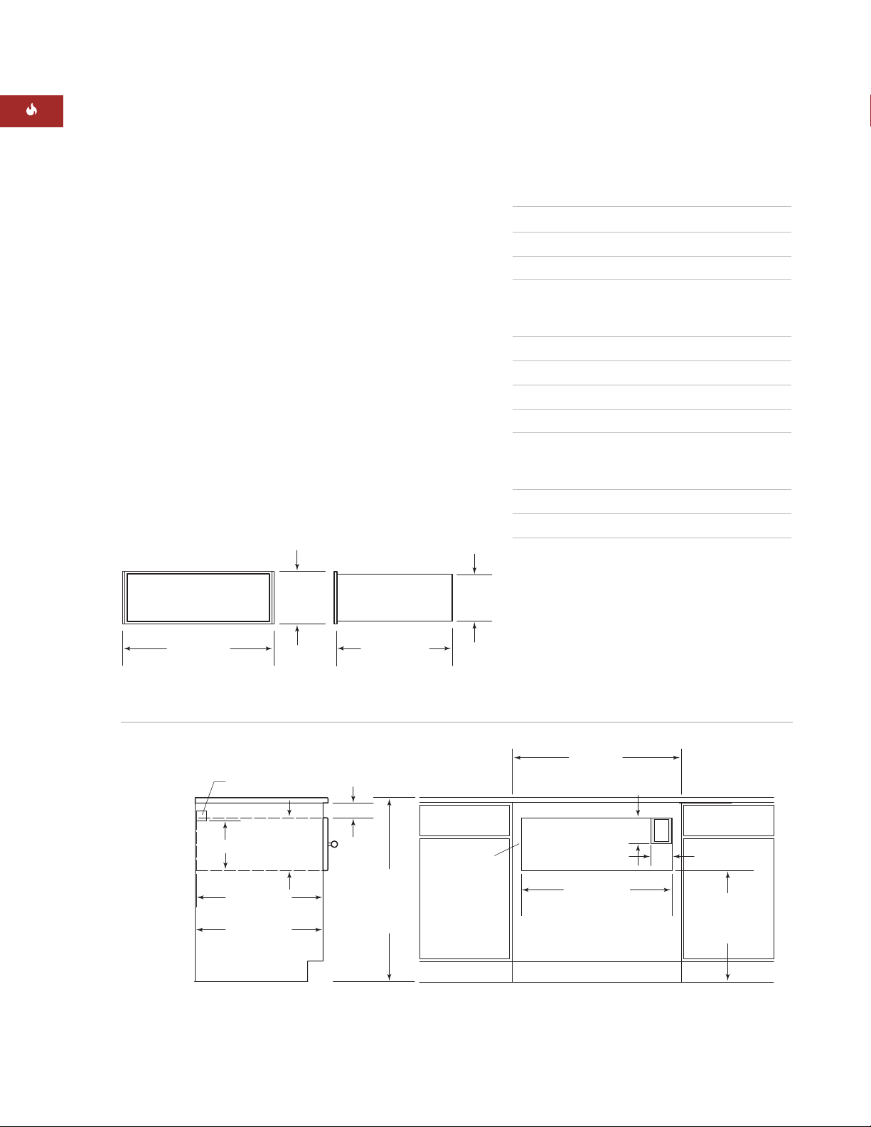
82
WÄRMESCHUBLADE VON WOLF
MODELL ICBWWD30
mit integrierter Schubladenfront
Gesamtbreite 746 mm
Gesamthöhe 257 mm
Gesamttiefe* (hinter Rahmen) 597 mm
Mindestschrankanforderungen
Verkleidung 838 mm B x 610 mm T
Voll integriert 838 mm B x 635 mm T
Mindesttragfähigkeit des Sockels 91 kg
Öffnungsbreite 749 mm
Öffnungshöhe 260 mm
Öffnungstiefe** 610 mm
Mindestplattengröße
Verkleidung 762 mm B x 264 mm H
Voll integriert 746 mm B x 257 mm H
Mindestplattenstärke 16 mm
Plattenhöchstgewicht 11 kg
*10 mm zusätzlich für die Kabelstärke einkalkulieren.
**Für die voll integrierte Ausführung die Stärke der
Schubladenfront zur Öffnungstiefe hinzuaddieren.
GESAMTBREITE
746 mm
597 mm
HINTER RAHMEN
229 mm257 mm
Gesamtabmessungen – Integrierte Schubladenfront
Integrierte Schubladenfront – Verkleidungsausführung
INTEGRIERTE SCHUBLADENFRONT
TECHNISCHE DATEN ZUR
INSTALLATION
Die nachstehenden Abbildungen enthalten die
Gesamtabmessungen und technischen Daten
zur Installation für die Wärmeschublade von
Wolf mit integrierter Schubladenfront. Die
Wärmeschublade mit integrierter Schubladenfront kann in einer Verkleidungsausführung oder
einer voll integrierten Ausführung verwendet
werden, wobei sie komplett in den Schrank
versenkt ist.
Denken Sie daran, dass die Größe der maßangefertigten Verkleidung für die Wärmeschublade mit
integrierter Front je nach spezifischer Installation
unterschiedlich ausfällt. In der folgenden Tabelle
finden Sie Mindestabmessungen für die Verkleidungs- und voll integrierten Plattenausführungen.
Installationsanweisungen für die integrierte
Schubladenfront finden Sie auf Seite 90–92.
Diese Anweisungen sind auch im integrierten
Schubladenfrontsatz enthalten.
KIPPSCHUTZ
51 mm x 51 mm
ÖFFNUNGSHÖHE
251 mm
*Genügend Platz für die Positionierung des Kippschutzblocks und der Überlappung der Schubladenfront einkalkulieren.
**Überlappung der dekorativen Schubladenfront ist je nach Größe der maßangefertigten Platte unterschiedlich.
260 mm
ÖFFNUNGSTIEFE
610 mm
min.
SCHRANKTIEFE
610 mm
min.
ABMESSUNG
VARIIERT*
STANDARD-
ZU ARBEITS-
914 mm
HÖHE
BODEN
PLATTE
EINE
ÜBERLAPPUNG
DER DEKORATIVEN
SCHUBLADEN-
FRONT AUF
ALLEN SEITEN
EINKALKULIEREN**
EMPFOHLENE SCHRANKBREITE
762 mm
127 mm
102 mm
ÖFFNUNGSBREITE
749 mm
838 mm
E
UNTERSEITE DER
ÖFFNUNG
ZUM BODEN
127 mm
Page 83
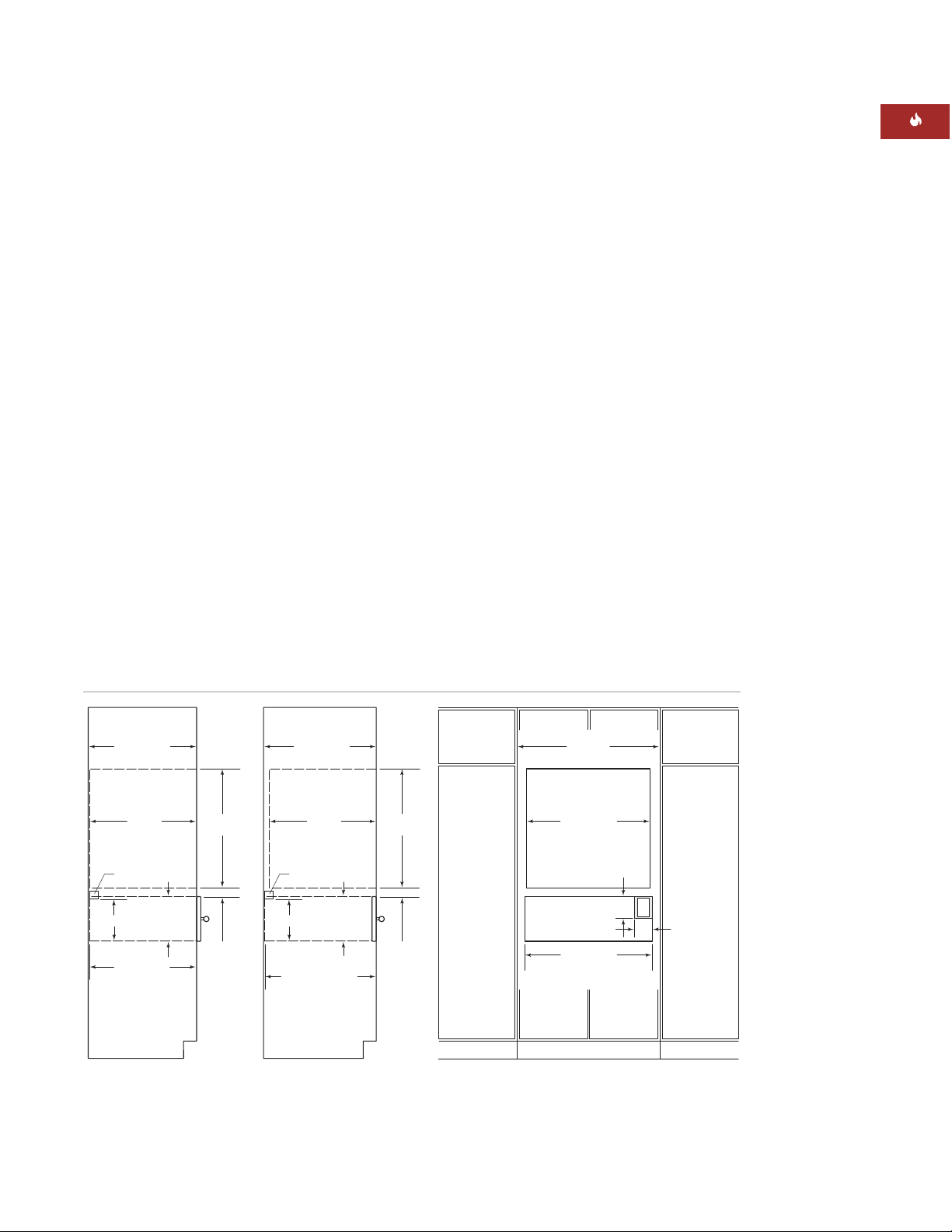
83
INSTALLATIONSANWEISUNGEN
Integrierte Schubladenfront – Voll integrierte Ausführung
INTEGRIERTE SCHUBLADENFRONT
VERKLEIDUNGSAUSFÜHRUNG
Für die Wärmeschublade mit integrierter
Schubladenfront wird bei Verwendung der
Verkleidungsausführung ein Schrank mit einer
Mindestbreite von 838 mm und einer Mindesttiefe
von 610 mm benötigt. Es ist eine Sockeltragfähigkeit von mindestens 91 kg erforderlich.
Siehe die Abbildung auf Seite 82.
VOLL INTEGRIERTE AUSFÜHRUNG
WICHTIGER HINWEIS:
Bei der voll integrierten
Ausführung muss die Wärmeschublade in den
Schrank versenkt werden. Es wird ein Schrank
mit einer Mindesttiefe von 635 mm benötigt,
wenn die Frontplatte bündig mit den angrenzenden Schränken abschließen soll.
Wenn Sie die Wärmeschublade mit der integrierten Schubladenfront in einer voll integrierten
Ausführung installieren, wird ein Schrank mit
einer Mindestbreite von 838 mm und einer
Mindesttiefe von 635 mm benötigt. Es ist eine
Sockeltragfähigkeit von mindestens 91 kg
erforderlich. Siehe die Abbildung unten.
UNTERTHEKENINSTALLATION
Bei Unterthekeninstallationen wird ein Abstand
von 597 mm von der Unterseite der Wärmeschubladenöffnung bis zum Boden empfohlen.
Die Schublade muss mindestens 127 mm über
dem Boden oder 25 mm über der Sockelleiste
installiert werden.
Die Wärmeschublade von Wolf mit einer integrierten Schublade kann unter einem 762 mm
oder 914 mm breiten Elektro- oder Gaskochfeld
installiert werden, wenn die Wärmeschublade von
oben nach unten vollständig eingeschlossen ist.
Weitere technische Daten finden Sie in den Installationsanweisungen für das Kochfeld. Die Abmessungen sind je nach spezifischer Installation
unterschiedlich.
SCHRANKTIEFE
610 mm
min.
610 mm
min.
KIPPSCHUTZ
51 mm x 51 mm
ÖFFNUNGS-
min.
260 mm
610 mm
HÖHE
251 mm
ÖFFNUNGSTIEFE
*Die Abmessung kann sich je nach Größe der Schubladenfrontplatte vergrößern.
691 mm
38 mm
min.*
SCHRANKTIEFE
635 mm
min.
610 mm
min.
KIPPSCHUTZ
51 mm x 51 mm
251 mm
STÄRKE DER
SCHUBLADENFRONT
FÜR ÖFFNUNGSTIEFE
610 mm +
VOLL INTEGRIERTE AUSFÜHRUNGVERKLEIDUNGSAUSFÜHRUNG
ÖFFNUNGS-
HÖHE
260 mm
691 mm
38 mm
min.*
SCHRANKBREITE
838 mm
724 mm
30-IN-BACKOFEN-
ÖFFNUNGSBREITE
127 mm
E
102 mm
ÖFFNUNGSBREITE
WÄRMESCHUBLADE
749 mm
HINWEIS: Die Position der Stromversorgung entnehmen Sie den technischen
Daten zum 762-mm-Einzeleinbaubackofen.
Page 84
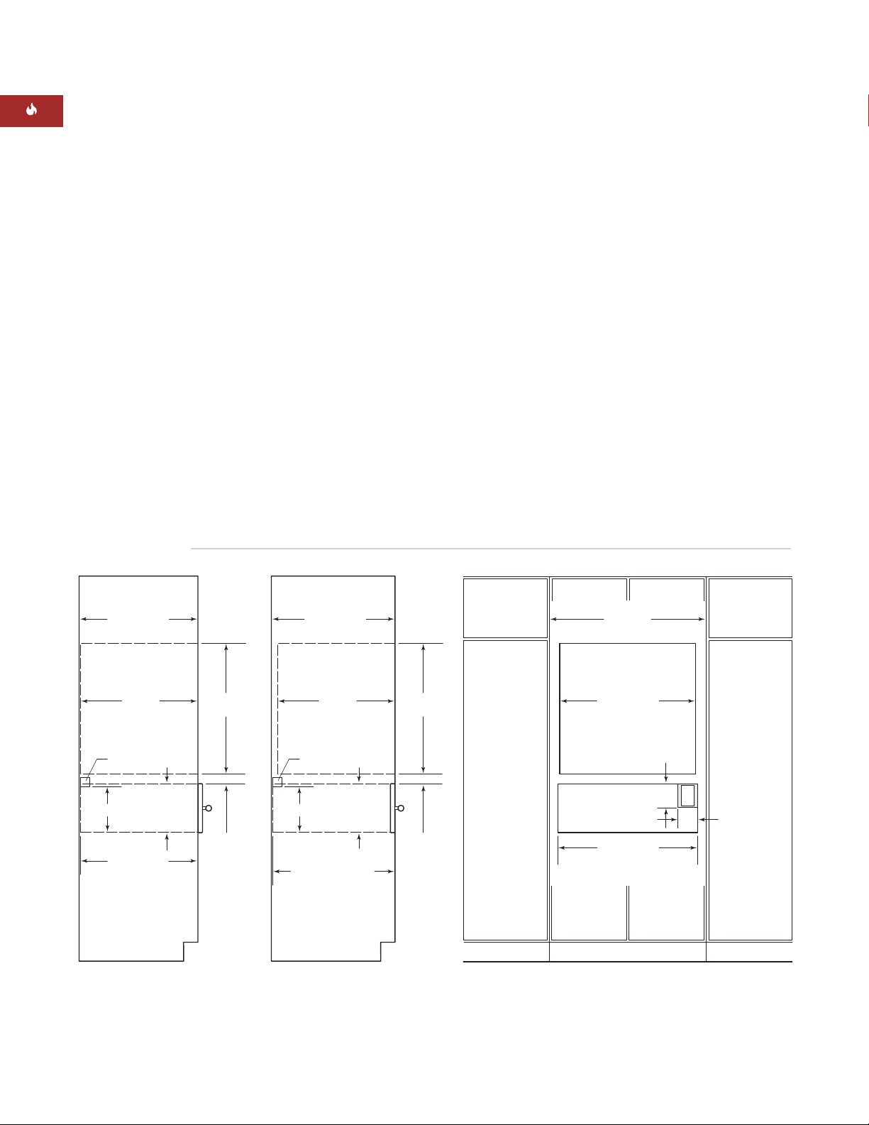
84
WÄRMESCHUBLADE VON WOLF
WICHTIGER HINWEIS:
Eventuell ist ein zusätzlicher Freiraum zwischen Wärmeschublade und
Backofenöffnungen erforderlich. Stellen Sie
sicher, dass die Backofenträger die Innenabmessungen, die für die Wärmeschublade erforderlich
sind, nicht behindern.
Wenn die Wärmeschublade unter einem Einbaubackofen installiert wird, muss ein Mindestabstand von 38 mm zwischen Wärmeschublade und
Backofenöffnungen für den Kippschutzblock und
die Backofenplattform eingehalten werden. Bei
der Installation über einem Einbaubackofen sind
mindestens 22 mm erforderlich.
WICHTIGER HINWEIS:
In einer Verkleidungsausführung muss der Zwischenraum zwischen
Wärmeschublade und integrierten Backofenöffnungen je nach Größe der Verkleidungsplatte
und Überlappung vergrößert werden.
INTEGRIERTE SCHUBLADENFRONT
INSTALLATION MIT EINBAUBACKOFEN
Die Wärmeschublade von Wolf mit der integrierten Schubladenfront kann unter oder über einem
762-mm- oder 914-mm-Einzeleinbaubackofen
installiert werden, sofern die Wärme-schublade
oben und unten vollständig eingeschlossen ist.
Siehe die Abbildung unten. Weitere technische
Daten entnehmen Sie den Installationsanweisungen, die im Lieferumfang des Einbaubackofens
enthalten sind. Die Abmessungen sind je nach
spezifischer Installation unterschiedlich.
Die Wärmeschublade von Wolf ist für die Installation mit Einbaubacköfen von Wolf konstruiert und
verfügt über die entsprechende behördliche
Zulassung.
Die Plattform der Wärmeschublade muss 91 kg
tragen können. Sie muss sich mindestens 25 mm
über der Sockelleiste befinden, damit eine Überlappung der Einfassung der Wärmeschublade
möglich ist.
Installation mit Einbaubackofen – Integrierte Schubladenfront
SCHRANKTIEFE
610 mm
min.
610 mm
min.
KIPPSCHUTZ
51 mm x 51 mm
ÖFFNUNGS-
251 mm
ÖFFNUNGSTIEFE
min.
*Die Abmessung kann sich je nach Größe der Schubladenfrontplatte vergrößern.
HÖHE
260 mm
610 mm
691 mm
38 mm
min.*
SCHRANKTIEFE
635 mm
min.
610 mm
min.
KIPPSCHUTZ
51 mm x 51 mm
251 mm
SCHUBLADENFRONT
FÜR ÖFFNUNGSTIEFE
VOLL INTEGRIERTE AUSFÜHRUNGVERKLEIDUNGSAUSFÜHRUNG
ÖFFNUNGS-
STÄRKE DER
610 mm +
HÖHE
260 mm
691 mm
38 mm
min.*
SCHRANKBREITE
838 mm
724 mm
30-IN-BACKOFEN-
ÖFFNUNGSBREITE
127 mm
102 mm
ÖFFNUNGSBREITE
WÄRMESCHUBLADE
749 mm
HINWEIS: Die Position der Stromversorgung entnehmen Sie den technischen
Daten zum 762-mm-Einzeleinbaubackofen.
E
Page 85
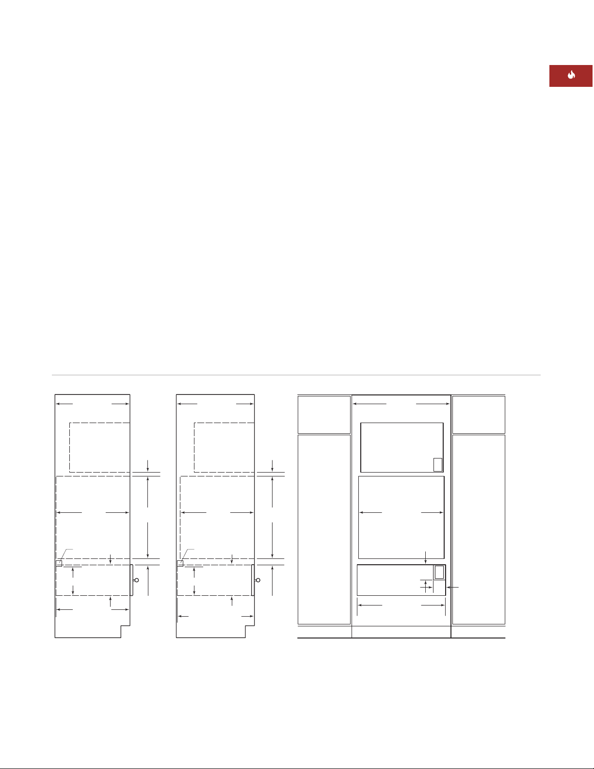
85
INSTALLATIONSANWEISUNGEN
Installation mit 762-mm-Einbaubackofen und Mikrowellenherd – Integrierte Schubladenfront
Weitere Einzelheiten entnehmen Sie den Installationsanweisungen, die im Lieferumfang des
Einbaubackofens und Mikrowellenherds enthalten
sind. Die Abmessungen sind je nach spezifischer
Installation unterschiedlich.
Die Wärmeschublade von Wolf mit der integrierten Schubladenfront kann neben oder über einer
anderen Wärmeschublade von Wolf installiert
werden, sofern jede Wärmeschublade oben
und unten vollständig eingeschlossen ist.
INTEGRIERTE SCHUBLADENFRONT
INSTALLATIONSOPTIONEN
Die Wärmeschublade von Wolf mit integrierter
Schubladenfront kann in Kombination mit einem
762-mm-Einzeleinbaubackofen und einem
Mikrowellenherd mit einer Einfassung von
762 mm installiert werden, sofern die
Wärmeschublade oben und unten vollständig
eingeschlossen ist. Siehe die Abbildung unten.
Die Wärmeschublade von Wolf mit der integrierten Schubladenfront kann kann außerdem in
Kombination mit einem 914-mm-Einzeleinbaubackofen und einem Mikrowellenherd mit
einer Einfassung von 914 mm installiert werden.
Die Plattform der Wärmeschublade muss 91 kg
tragen können. Sie muss sich mindestens 25 mm
über der Sockelleiste befinden, damit eine Überlappung der Einfassung der Wärmeschublade
möglich ist.
SCHRANKTIEFE
610 mm
min.
SCHRANKTIEFE
635 mm
min.
SCHRANKBREITE
838 mm
ROHBAUÖFFNUNG FÜR
25 mm
610 mm
min.
KIPPSCHUTZ
51 mm x 51 mm
ÖFFNUNGS-
min.
260 mm
610 mm
HÖHE
251 mm
ÖFFNUNGSTIEFE
*Die Abmessung kann sich je nach Größe der Schubladenfrontplatte vergrößern.
691 mm
38 mm
min.*
VOLL INTEGRIERTE AUSFÜHRUNGVERKLEIDUNGSAUSFÜHRUNG
610 mm
min.
KIPPSCHUTZ
51 mm x 51 mm
ÖFFNUNGS-
251 mm
SCHUBLADENFRONT
FÜR ÖFFNUNGSTIEFE
HÖHE
260 mm
STÄRKE DER
610 mm +
25 mm
691 mm
38 mm
min.*
HINWEIS: Die Position der Stromversorgung entnehmen Sie den technischen
Daten zum 762-mm-Einzeleinbaubackofen.
MIKROWELLENHERD
724 mm
30-IN-BACKOFEN-
ÖFFNUNGSBREITE
127 mm
102 mm
ÖFFNUNGSBREITE
WÄRMESCHUBLADE
749 mm
E
E
Page 86

Außerdem beachten Sie alle örtlichen
Vorschriften und Richtlinien, wenn Sie die
Versorgung installieren.
86
WÄRMESCHUBLADE VON WOLF
ELEKTROVORAUSSETZUNGEN
Für die Wärmeschublade von Wolf wird eine
separate, geerdete Versorgung von 220– 240 V AC,
50/60 Hz, benötigt, und sie muss an einem einzelnen, ordnungsgemäß geerdeten Stromkreis
angeschlossen und mit einem 15- oder 20Amp-Schutzschalter oder einer Sicherung mit
Zeitverzögerung geschützt werden.
WICHTIGER HINWEIS:
Die Wärmeschublade
muss in eine passende 3-polige, geerdete Steckdose eingesteckt werden, um die Möglichkeit
eines Stromschlags zu minimieren.
Wenn sich die Steckdose hinter dem Gerät
befindet, muss sichergestellt werden, dass sie
bündig mit der Rückwand abschließt. Die Position
der Stromversorgung entnehmen Sie der Installationsabbildung für Ihre spezifische Installation auf
Seite 79–85.
Wenn zwei Wärmeschubladen nebeneinander
installiert werden, können sie von derselben
Steckdose aus betrieben werden. Für diese Installation ist ein 30-Amp-Schutzschalter erforderlich.
ACHTUNG
Kein Verlängerungskabel bzw. keinen
zweipoligen Stecker verwenden. Für dieses
Gerät ist eine elektrische Erdung erforderlich.
Den Erdungsstift des Netzkabels nicht
entfernen.
VORSICHT
Die Steckdose muss von einem qualifizierten Elektriker geprüft werden, um
sicherzustellen, dass sie mit der richtigen
Polarität verdrahtet ist. Stellen Sie sicher,
dass die Steckdose 220–240 V AC speist
und ordnungsgemäß geerdet ist.
WICHTIGER
HINWEIS
Bei der Installation
der Versorgungseinrichtungen müssen
Sie alle örtlichen
Vorschriften und
Richtlinien
beachten.
Page 87

87
INSTALLATIONSANWEISUNGEN
SCHRANKTRÄGER
WICHTIGER HINWEIS:
Wenn die Wärmeschublade mit einem Einbaubackofen installiert
wird, ist eventuell ein zusätzlicher Freiraum
zwischen Öffnungen erforderlich. Stellen Sie
sicher, dass die Backofenträger die Innenabmessungen, die für die Wärmeschublade erforderlich
sind, nicht behindern.
Die Wärmeschublade mit der Schubladenfront
aus Edelstahl kann entweder durch eine solide
Plattform, Laufleisten mit den Maßen 51 mm x
51 mm oder Laufleisten mit den Maßen 51 mm x
102 mm abgestützt werden. Die Plattform bzw.
die Laufleisten müssen waagrecht und fest
montiert sein und bündig mit der Unterkante
der Öffnung abschließen. Sie müssen eine
Tragfähigkeit von 91 kg haben.
Wenn eine integrierte Schubladenfront verwendet
wird, muss sie von einer 16 mm hohen, soliden
Plattform abgestützt werden. Die Plattform muss
in der Öffnung versenkt sein und eine Überlappung des Bunds der Wärmeschublade ermöglichen. Weitere Details finden Sie auf Seite 90.
Die Plattform muss waagrecht und fest montiert
sein und eine Tragfähigkeit von 91 kg haben.
WICHTIGER HINWEIS:
Stellen Sie sicher, dass
die Plattform oder Laufleisten waagrecht sind.
Nach Abschluss der Installation kann die
Wärmeschublade nicht mehr nivelliert werden.
AUSPACKEN DER WÄRMESCHUBLADE
Die Wärmeschublade auf einer flachen Oberfläche
auspacken. Alles Verpackungsmaterial und Klebeband in der Wärmeschublade entfernen und
entsorgen. Die Packung mit den zwei Holzschrauben, die für die Installation benötigt
werden, darf nicht weggeworfen werden.
Page 88
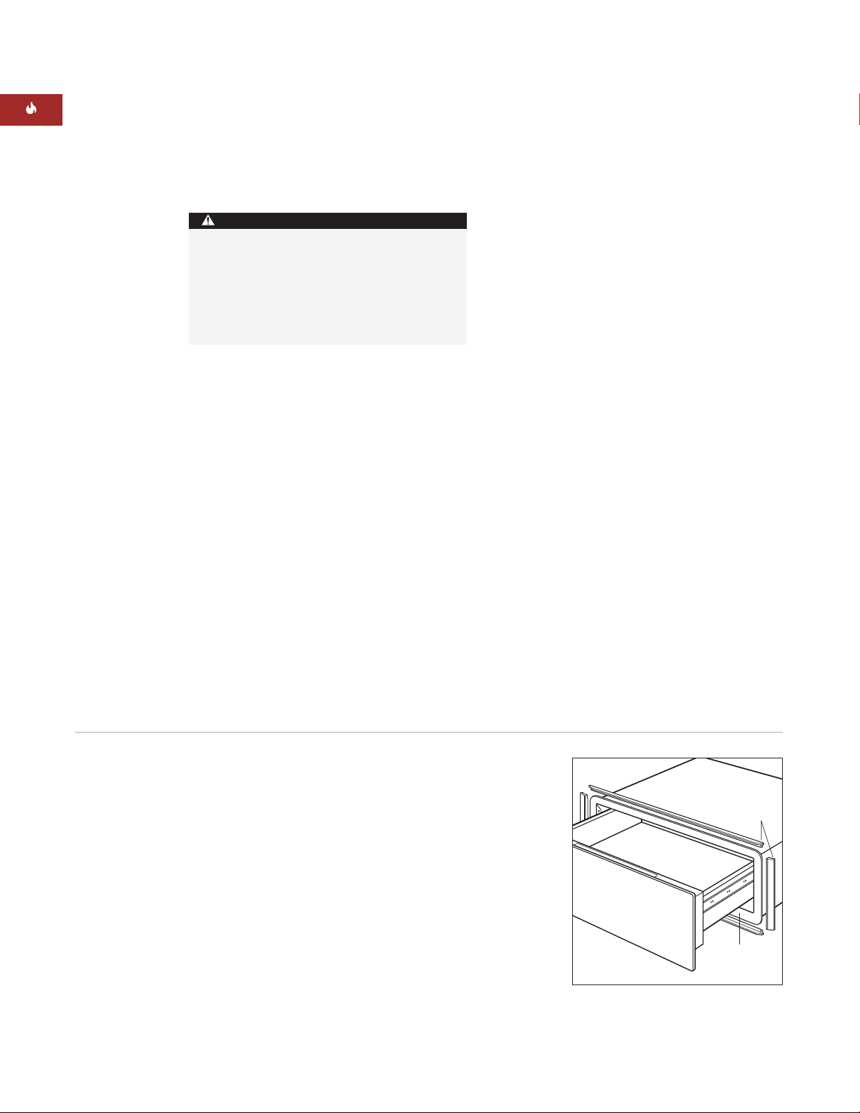
EINFASSUNG DER WÄRMESCHUBLADE
INSTALLIEREN
Das gesamte Verpackungsmaterial von der Einfassung entfernen. Im Lieferumfang des Schubladenfrontsatzes aus Edelstahl sind zwei lange Einfassungsteile für den oberen und unteren Bund der
Wärmeschublade und zwei kurze Einfassungsteile
für die Seiten enthalten. Jedes Einfassungsteil ist
mit einer Rille versehen, die über die Kante des
Bunds passt. Siehe die Abbildung unten.
Eines der langen Einfassungsteile so auf den
oberen Bund der Wärmeschublade positionieren,
dass die Rille auf den oberen Bund passt.
Als Nächstes eines der kleinen Seiteneinfassungsteile auf den linken Bundrand positionieren. Die
obere Einfassung und Seiteneinfassung sollten
ineinander verschachtelt werden. Auf der Rückseite der Einfassungsteile befinden sich
Montagelöcher. Die beiden Teile mit den im Satz
enthaltenen kleinen 8 mm langen Schrauben
aneinander befestigen.
Dieses Verfahren zum Befestigen der Einfassung
rechts und unten wiederholen.
88
WÄRMESCHUBLADE VON WOLF
FRONTPLATTE AUS
EDELSTAHL
KIPPSCHUTZBLOCK INSTALLIEREN
Einen Kippschutzblock mit den Abmessungen
51 mm x 51 mm oder 51 mm x 102 mm an der
Rückwand des Schranks installieren. Wenn die
Wärmeschublade unter einem Einbaubackofen
installiert wird, können Sie eine 22 mm starke
Plattform verwenden, um die Einfassung der
Wärmeschublade auf die Einfassung des Backofens abzugleichen. Die Plattform fungiert als
Kippschutzvorrichtung für die Wärmeschublade.
Beide Ausführungen sind in den Abbildungen
auf Seite 80 dargestellt.
ACHTUNG
Ein Kippschutz oder eine Plattform muss
installiert werden, um ein Abkippen der
Wärmeschublade nach vorne zu verhindern,
wenn die Schublade geöffnet oder beladen
wird. Ansonsten besteht Verletzungsgefahr,
und der Schrank könnte beschädigt werden.
Bund
Position der
Montagelöcher
Einfassung der Wärmeschublade
installieren
Page 89

89
INSTALLATIONSANWEISUNGEN
FRONTPLATTE AUS
EDELSTAHL
FRONTPLATTE INSTALLIEREN
Alle Verpackungsmaterialien vom Griff und von
der Frontplatte entfernen. Die Schutzabdeckung
vorsichtig von der Frontplatte aus Edelstahl
abnehmen. Die Klebschicht sollte sich sauber
von der Oberfläche abziehen lassen. Eventuell
verbleibende Klebstoffreste sollte mit einem
milden Reinigungsmittel gereinigt werden.
Um den Griff an der Frontplatte zu befestigen, die
Löcher in den Abstandsbolzen und dem Griff auf
die Löcher in der Frontplatte ausrichten. Die Griffschrauben durch die Löcher in der Frontplatte
einführen und die Schrauben an der Frontplatte
festziehen.
Den oberen Vorsprung der Frontplatte über die
Schubladenfront schieben. Drei Schrauben in die
Oberseite des Frontplattenvorsprungs durch die
Schubladenfrontbaugruppe einführen und die
Schrauben festziehen. Drei Schrauben in die
Unterseite der Frontplatte durch die Schubladenfrontbaugruppe einführen und die Schrauben
festziehen. Siehe die Abbildung unten.
Die Stromzufuhr zur Steckdose unterbrechen.
WÄRMESCHUBLADE INSTALLIEREN
Die linke Ecke der Wärmeschublade in die
Öffnung schieben. Wenn die Steckdose in der
Öffnung installiert ist, das Netzkabel in die Steckdose einstecken. Das überhängende Kabel sollte
hinter oder neben dem Gerät aufgerollt werden.
Wenn sich die Steckdose in einem angrenzenden
Schrank befindet, das Netzkabel durch das Loch
in der Schrankwand führen. Die Schublade zurück
in die Öffnung schieben, bis die Einfassung an
der Schrankfront anliegt. Sicherstellen, dass
das Netzkabel nicht unter der Wärmeschublade
festhängt.
WICHTIGER HINWEIS:
Die Schublade nicht
am Griff hochziehen und sie nicht in Position
drücken. Dadurch könnte die Schaltblende
verkratzt werden.
Die Wärmeschublade vollständig herausziehen.
Pilotlöcher in jedes Seitenloch bohren, das sich
weiter vorne an jeder Seite der Wärmeschublade
befindet. Die im Lieferumfang des Geräts enthaltenen Holzschrauben installieren. Siehe die Abbildung unten.
Die Stromzufuhr zur Steckdose wieder herstellen.
Position des
Seitenlochs
Schubladenfront-
Baugruppe
Vor sprung
Frontplatte
Installation der WärmeschubladeGriff anbringen
Page 90

90
INTEGRIERTE FRONTPLATTE
SCHLAGLEISTEN UND PLATTFORM
INSTALLIEREN
Für eine Verkleidungs- oder voll integrierte
Ausführung müssen Sie eine versenkte Plattform
und Schlagleisten mit den folgenden Abmessungen in die Öffnung installieren.
Abmessungen obere Schlagleiste
749 mm B x 13 mm H x 51 mm T
Abmessungen seitliche Schlagleiste
13 mm B x 232 mm H x 51 mm T
Plattformabmessungen
749 mm B x 16 mm H x 603 mm T
Tiefe der Plattform kann sich je nach
Schranktiefe erhöhen.
Bei einer Verkleidungsausführung müssen die
Plattform und Schlagleiste um 5 mm versenkt
sein. Bei einer voll integrierten Ausführung
müssen sie um 5 mm zuzüglich der Stärke der
Schubladendekorplatte versenkt sein, damit die
Dekorplatte bündig mit der Vorderseite des
Schranks abschließt. Es muss sichergestellt
werden, dass die Plattform fest montiert wird,
damit sie eine Tragfähigkeit von mindestens
91 kg hat. Siehe die Abbildungen weiter unten.
WICHTIGER HINWEIS:
Bei einer Verkleidungsausführung dürfen die Schlagleisten
nicht um mehr als 5 mm versenkt sein. Ein
tieferes Versenken kann dazu führen, dass
sich die Schublade nicht richtig schließt.
WÄRMESCHUBLADE VON WOLF
WICHTIGER HINWEIS:
Stellen Sie sicher, dass
der Innenvorsprung der Öffnung und die Frontfläche des Regals sowie die Schlagleisten bearbeitet sind. Einige dieser Bereich sind sichtbar,
wenn die Schublade offen ist.
WICHTIGER HINWEIS:
Achten Sie auf die
Position der Montagelöcher auf dem
Wärmeschubladenrahmen, um sicherzustellen,
dass die zum Befestigen der Schlagleisten
verwendeten Schrauben nicht die Schraubenlöcher zum Montieren der Wärmeschublade
stören.
Plattform
Obere Schlagleiste
Seitliche
Schlagleiste
Schranköffnung
Schlagleisten und Plattform
5 mm versenkt zuzüglich
Stärke der Dekorplatte
Plattform
Obere Schlagleiste
Seitliche
Schlagleiste
Schranköffnung
Schlagleisten und Plattform
5 mm versenkt
Versenkte Schlagleisten und Plattform –
voll integrierte Ausführung
Versenkte Schlagleisten und Plattform –
Verkleidungsausführung
Page 91

91
INSTALLATIONSANWEISUNGEN
Position des
Seitenlochs
Installation der Wärmeschublade
INTEGRIERTE FRONTPLATTE
KIPPSCHUTZBLOCK INSTALLIEREN
Einen Kippschutzblock mit den Abmessungen
51 mm x 51 mm oder 51 mm x 102 mm an der
hinteren Schrankwand installieren (siehe die
Installationsabbildung für Ihre spezifische
Installation auf Seite 83–86).
WÄRMESCHUBLADE INSTALLIEREN
Die Stromzufuhr zur Steckdose unterbrechen. Die
linke Ecke der Wärmeschublade in die Öffnung
schieben. Wenn die Steckdose in der Öffnung
installiert ist, das Netzkabel in die Steckdose
einstecken. Das überhängende Kabel sollte hinter
oder neben dem Gerät aufgerollt werden. Wenn
sich die Steckdose in einem angrenzenden
Schrank befindet, das Netzkabel durch das Loch
in der Schrankwand führen. Das Gerät zurück in
die Öffnung schieben, bis der Wärmeschubladenbund an den versenkten Schlagleisten und der
Plattform anliegt. Sicherstellen, dass das Netzkabel nicht unter der Wärmeschublade festhängt.
Die Schublade vollständig herausziehen.
Pilotlöcher in jedes Seitenloch bohren, das sich
weiter vorne an jeder Seite der Wärmeschublade
befindet. Die im Lieferumfang der Wärmeschublade enthaltenen Holzschrauben installieren. Siehe die Abbildung unten. Die Stromzufuhr zur Steckdose wieder herstellen.
Page 92

92
WÄRMESCHUBLADE VON WOLF
INTEGRIERTE FRONTPLATTE
FRONTPLATTE AN SCHUBLADE
INSTALLIEREN
Die Kommunikationsleitung vom Kommunikationsanschluss abtrennen. Der Kommunikationsanschluss wird ausgebaut, indem die Halteklammer
auf der Vorderseite der Montageplatte niedergedrückt und anschließend die Halteklammerseite
des Anschlusses durch die Montageplatte gedrückt
und dann aus der Montageplatte heraus gedreht
wird. Den ausgebauten Kommunikationsanschluss
in die Schubladenrahmenbaugruppe positionieren.
Die Metallplatte von der integrierten Schubladenfront auf die Rückseite des Dekorfrontplatte
platzieren. Alle Löcher in der Metallplatte auf
die Dekorplatte einzeichnen.
Eine Linie von der Kante der Langlöcher zum
entsprechenden Langloch darunter zeichnen. Die
Markierungen auf der Rückseite der Dekorplatte
sollten wie in der unteren Plattenabbildung
aussehen.
Für jede runde Markierung auf der Dekorplatte
(12 Positionen, sechs für Schraubköpfe und sechs
für die Rückseiten der Gummipuffer) ein 12,7 mm
großes und 6,35 mm tiefes Loch in die Rückseite
der Platte bohren.
Die rechteckigen Bereiche (8 Stellen), die auf der
Rückseite der Dekorplatte markiert sind, 6,35 mm
tief ausfräsen.
Die Griffbeschläge an der Vorderseite der Dekorplatte anbringen. Im integrierten Schubladenfrontsatz ist kein Griff enthalten. Dadurch kann
der Hauseigentümer die Beschläge an die angrenzenden Schränke anpassen.
Mithilfe der sechs Schrauben, die im Lieferumfang der Wärmeschublade enthalten waren,
die Metallplatte vom integrierten Schubladenfrontsatz auf der Wärmeschubladenfront installieren. Sicherstellen, dass die gebürstete Seite
der Metallplatte zur Wärmeschublade hin weist.
Die sechs Gummipuffer, die im Wärmeschubladenfrontsatz enthalten sind, auf der Metallplatte installieren. Die Dekorplatte an der
Wärmeschublade befestigen, indem die sechs
12,7-mm-Montageschrauben, die im Satz
enthalten sind, durch die Rückseite der Wärmeschublade in die Dekorfrontplatte eingeschraubt
werden.
Gummipuffer
Dekorplatte
Schraube
Metallplatte
Position der Puffer und
Montageschrauben
Rückansicht der Dekorplatte
Page 93

93
KON TAK TINFORMATIONEN
Website:
wolfappliance.com
FEHLERSUCHE
WICHTIGER HINWEIS:
Wenn die Wärmeschublade nicht richtig funktioniert, führen
Sie zur Fehlersuche folgende Schritte aus:
Stellen Sie sicher, dass die Wärmeschublade
mit Strom versorgt wird.
Prüfen Sie die elektrischen Anschlüsse, um
sicherzustellen, dass die Installation richtig
abgeschlossen wurde.
Lesen Sie die Anweisungen zur Fehlersuche
in der Bedienungs- und Pflegeanleitung der
Wärmeschublade von Wolf.
Wenn die Wärmeschublade immer noch nicht
richtig funktioniert, wenden Sie sich an einen
Vertragshändler oder eine regionale Vertriebsstelle von Wolf. Versuchen Sie auf keinen Fall,
die Wärmeschublade selbst zu reparieren.
WENN SERVICE ERFORDERLICH IST
Wenden Sie sich zwecks Service in Ihrer
Region entweder an Ihren Wolf-Vertragshändler oder besuchen Sie die Locator-Seite
auf unserer Website
wolfappliance.com
, um
nach der regionalen Vertriebsstelle im jeweiligen Land zu suchen.
Wenn Sie den Kundendienst anrufen, benötigen Sie die Modell- und Seriennummer der
Wärmeschublade. Beide Nummern sind auf
dem Produkttypenschild aufgeführt, das sich
im linken vorderen Bodenbereich des Innenschranks befindet. Um Zugang zum Typenschild zu erhalten, muss die Schublade ganz
offen sein. Siehe die Abbildung auf Seite 77 .
INSTALLATIONSANWEISUNGEN
Die Informationen und Abbildungen sind das urheberrechtlich geschützte Eigentum der Wolf Appliance, Inc.,
einem Tochterunternehmen der Sub-Zero, Inc. Weder
dieses Handbuch noch darin enthaltene Informationen
oder Abbildungen dürfen insgesamt oder teilweise
ohne die ausdrückliche schriftliche Genehmigung der
Wolf Appliance, Inc., einem Tochterunternehmen der
Sub-Zero, Inc., kopiert oder verwendet werden.
©Wolf Appliance, Inc. Alle Rechte vorbehalten.
Page 94

WOLF APPLIANCE, INC.
PO BOX 44848
MADISON, WI 53744 USA
WOLFAPPLIANCE.COM
811418 11/2007
 Loading...