

Page 1
FIND OUT MORE
THE WEB.
ON
WILBURCURTIS.COM
WW
W
WW
ILBURILBUR
ILBUR
ILBURILBUR
C C
C
C C
URTISURTIS
URTIS
URTISURTIS
C C
C
C C
OMPOMP
OMP
OMPOMP
ANYANY
ANY
ANYANY
, I, I
, I
, I, I
NCNC
NC
NCNC
Primo Cappuccino Instructions
MODEL PC-3
References in this manual to "Primo
Cappuccino" Throughout this service
manual, the Primo Cappuccino model
PC-3 is illustrated. This will be typical.
On all other models, PC-1, PC-2, PC-4
and HC-1. parts are common except
where noted.
..
.
..
C
ISO 9001 REGISTERED
WILBUR CURTIS COMPANY
Montebello, CA 90640
Table of Contents
UNPACKING . . . . . . . . . . . . . . . .
SETUP . . . . . . . . . . . . . . . . . .
COLD DRINKS . . . . . . . . . . . . . . .
ADJUSTING BEVERAGE STRENGTH . . . .
REPLACING LAMP & STARTER . . . . . . .
CLEANING & MAINTENANCE . . . . . . .
SIDE PANEL REMOVAL . . . . . . . . . . .
TROUBLESHOOTING . . . . . . . . . . . .
ILLUSTRATED PARTS BREAKDOWN . . . .
ILLUSTRATED PARTS LIST . . . . . . . .
WIRING DIAGRAM, PC-3 . . . . . . . . . .
WARRANTY . . . . . . . . . . . . . . . .
FOR THE LATEST SPECIFICATIONS AND INFORMATION GO TO
WWW.WILBURCURTIS.COM
PageDescription
1
1 - 2
3
3
3
3 - 5
5
5 - 7
8 - 9
11 - 12
13
14
Page 2
3
3
1
3
3
3
3
3
3
3
3
Unpacking
All products manufactured by the Wilbur Curtis Company are thoroughly inspected at the
factory and are warranted to be free of all defects or faulty workmanship. The Primo Cappuccino unit is packaged for maximum protection while being shipped. Make sure the shipping carton is not damaged or punctured. Unpack the carton carefully, inspecting the contents for any damage that may have occurred in transit. Report any damage immediately to
the freight company.
Setup
THIS EQUIPMENT IS TO BE INSTALLED TO COMPLY WITH THE APPLICABLE FEDERAL, STATE, OR LOCAL
PLUMBING AND ELECTRICAL CODES HAVING JURISDICTION.
The Primo Cappuccino unit should be located on a solid counter top. The counter top should
be level. Connect the water line from the water filter to the unit using ¼" copper tubing with
a flare fitting at the end. Some type of water strainer must be used to maintain a trouble-free
operation. In areas with extremely hard water, we suggest that an Everpure QC7-MH water
filter be installed.
NSF, The National Sanitation Foundation, requires the following water hookup:
1. A quick disconnect water connection or enough extra coiled tubing (at least 2x the
depth of the unit) so that the machine can be moved for cleaning underneath.
2 . An approved flow back prevention device, such as a double check valve to be installed
between the machine and the water supply.
Primo
Cappuccino
2
2
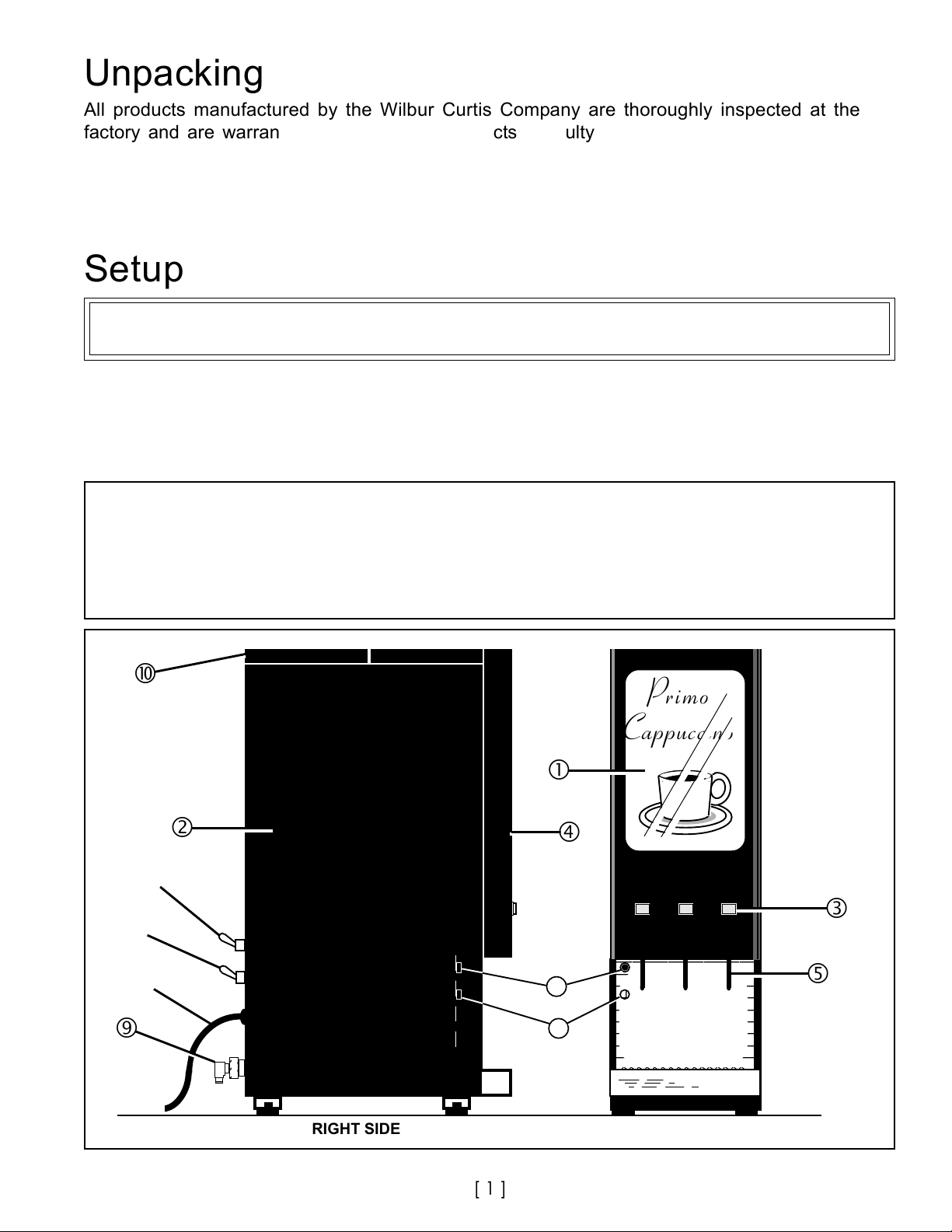
Figure 1. Location of Components on the Primo Cappuccino. PC-3 Shown, Others Similar.
RIGHT SIDE VIEW
[ 1 ]
11
12
23456789012
23456789012
23456789012
23456789012
23456789012
23456789012
23456789012
23456789012
FRONT VIEW
Page 3
Refer to figure 1. for index numbers ( ) in this section. Primo Cappuccino machines are
1
1
shipped with the power cord connected inside the machine. The power cord (8) ends with a
standard 3 pronged 120V plug. Check the serial plate on the side of the machine to make
sure of the electrical requirements for your unit.
Setup Steps
CAUTIONCAUTION
CAUTION DO NOT connect this brewer to hot water. Inlet valve not rated for hot water.
CAUTIONCAUTION
1. Connect a ¼" copper water line from your facility to the ¼" flare water inlet fitting (9)
of the valve, behind the machine. Water pressure going to the machine must be stable.
Use a water regulator to maintain constant pressure. Brewer works perfectly with
water pressures from 20 to 80 psi.
2. Make sure the thermostat is in the OFF position (turn stem all the way counterclockwise).
3. To Locate the thermostat:
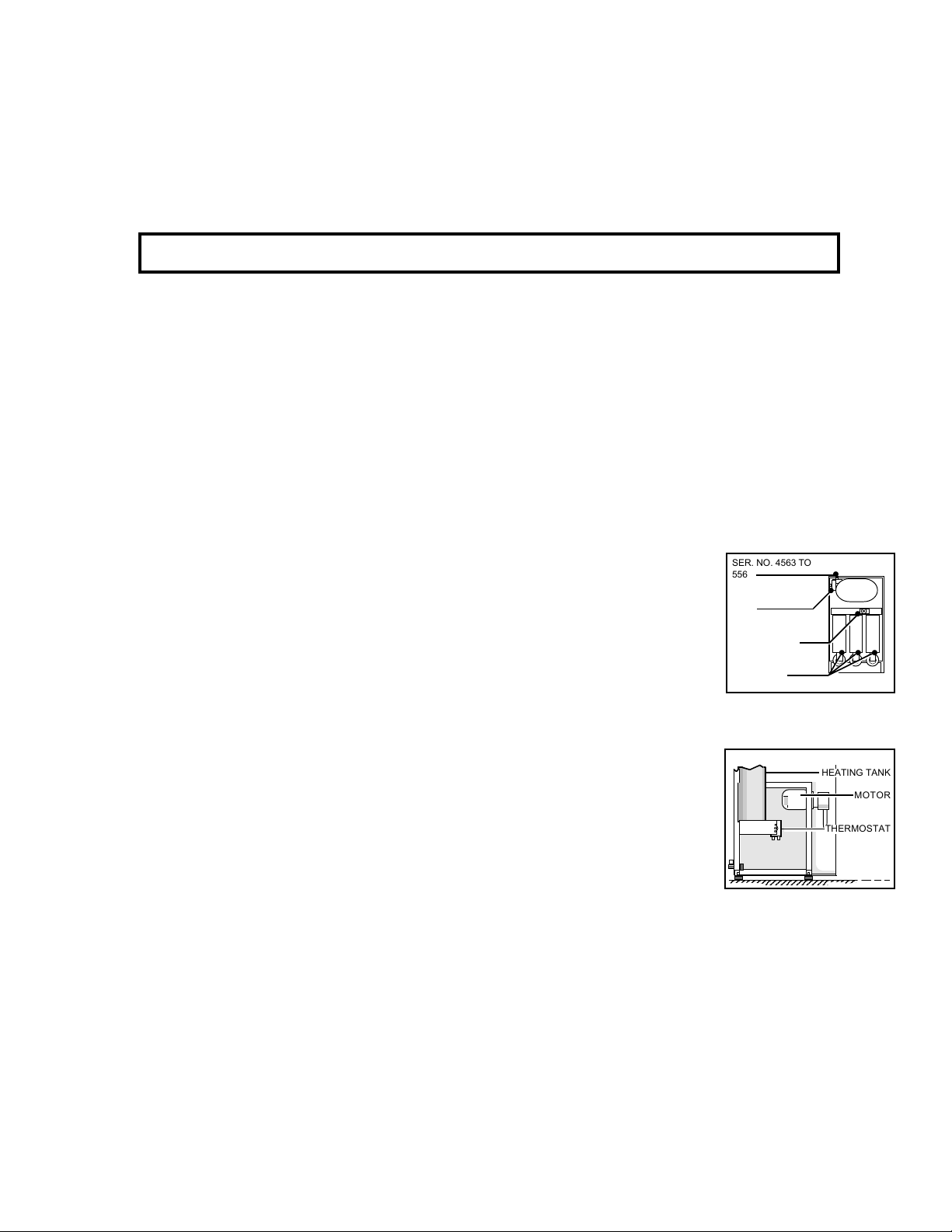
A. On later PC-3 and PC-4 units the thermostat is located behind the canisters. Open the
front door (4) and pull out the canisters.The thermostat is on the right side at the back
of the canister shelf. The knob will be sticking out from behind the cover.
B. See Fig. 2a. for the various thermostat locations used on the PC-3.
C. On PC-1, PC-2 and HC-1, thermostat is located behind the remov-
able left side panel, Figure 2b.
Remove the screws under the front section of the top cover (10),
slide forward and remove the top cover. Loosen the screw con-
necting the spout shield and side panel (2).
Hold panel by the edges and lift up to free screw heads on the
panel from the key holes on the frame. For a more detailed de-
scription see Side Panel Removal, page 5.
SER. NO. 4563 TO
5569
SER. NO. 0100 TO
4562
THERMOSTAT
SER. NO. 5570
THRU PRESENT
CANISTERS
TOP VIEW
Figure 2a. Thermostat
Location, PC-3.
4. Turn off the heating elements, switch (6), toggle down.
5. Plug the power cord into an electrical outlet rated at 20A.
HEATING TANK
MOTOR
THERMOSTAT
6. Switch on the toggle switch (7), up, sending power to the components in the machine. The lights (display window [1] & row of
switches [3]) on the front cover will activate and the heating tank
will start to fill. At this time the READY TO BREW light will come on.
Figure 2b. HC-1 &
PC-1, Side View.
7. When the heating tank has filled, turn on the thermostat by twisting the stem clockwise
as far as it will go. Switch on the toggle switch (6) to turn on the heating elements. The
READY TO BREW light will go off.
9. The heating tank requires about 30 minutes to get up to operating temperature, 195ºF.
The READY TO BREW light will come on when the water reaches this temperature.
10.Reinstall the left side panel (2) and top cover (10) and fill the canisters with powdered
cappuccino mix.
[ 2 ]
Page 4
Cold Drinks
Primo Cappuccino units that brew hot drinks can be setup for cold iced coffee operation.
Using the optional cold water system, cold water bypasses the hot water tank when the
first switch (left) is pressed. A seperate water inlet tube and valve draws cold water from
the main water line directly into the mixing cup.
To activate this system, open the front door. Pull out the product canisters and locate the
cold water switch (#47, illustration, fig. 13.) mounted on the canister shelf. Flip this switch
to COLD. Assemble canisters on the shelf and close the door.
NOTE: Use coffee product made for cold use only.
To setup all the flavor switches to dispense cold drinks only (no hot), the heating element
must be turned off. Look behind the machine; locate the two toggle switches. The top
switch is labeled HEATING ELEMENTS. Switch this one OFF. Allow hot water in tank to cool
down before using.
Adjusting the Beverage Strength
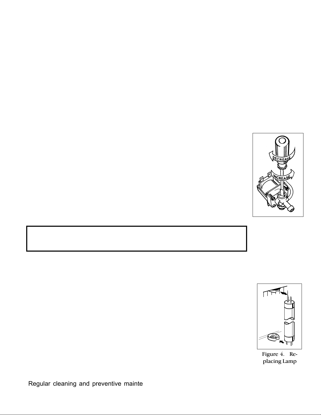
Adjusting the water flow rate allows you to determine the strength of
beverage you desire. Decreasing the flow rate will result in a stronger
beverage; increasing to weaken.
The dump valves are adjustable so that you can control the rate of the
water flow.
To Change the adjustment on the dump valves, use a slotted screwdriver. Turn the adjustment screw clockwise to decrease the flow rate;
counterclockwise to increase.
The dump valves are set at the factory for a flow rate of .8 ounce per
second; a higher rate will overflow the mixing cup.
Figure 3. Adjustment
NOTE The flow rate of the powder mix going to the mixing cup is fixed
by the speed of the motor and auger design. If you wish to change the
powder flow rate, various auger designs are available by special order.
Screw on Dump Valve
Replacing Lamp and Starter
Disconnect the power by unplugging the machine. To change a fluorescent
lamp, remove the panel inside the door and the light box. The fluorescent
lamp is held in its mounting with two contacts on top and two at the bottom. Take hold of the lamp and turn it slightly to free it from the socket.
Replace the lamp by aligning and inserting the lamp contacts as shown in
figure 4.. As you push the lamp into place, twist the lamp so that the other
contact seats in the socket.
To change a starter, remove by twisting slightly in the socket counterclockwise. The starter will separate from the starter base. Replace the starter by
pushing it into the base and twisting clockwise slightly.
Figure 4. Re-
placing Lamp
Cleaning & Maintenance
Regular cleaning and preventive maintenance is essential in keeping the Primo Cappuccino
coffee dispenser looking and working like new.
[ 3 ]
Page 5
CAUTION - When cleaning the unit, do not use cleansers, bleach liquids, powders or
any other substance that contains chlorine. These products promote corrosion and
will pit the stainless steel. USE OF THESE PRODUCTS WILL VOID THE WARRANTY.
DAILY CLEANING
1. Wipe off any spills, dust or debris from the exterior surfaces.
2. Wipe surfaces with a damp cloth.
3. Slide out the drip drawer and louvered cover. Wash out its contents. Dry these parts and
return them to the machine.
4. Clean around the dispensing area, wiping with a nontoxic cleaner. Dry thoroughly.
5. Flush the Whipper Chamber:
A. Turn power on.
B. Place a container under the dispensing spout to catch waste water.
C. Open the front door of the machine and locate the rinse switch (item 11, figure 1.).
D. Rinse each flavor by pushing and holding the rinse switch while at the same time
pushing the orange colored dispensing switch on the front panel. Continue until the
water runs clear.
E. Clean up any water that may have spilled.
FILL CANISTERS DAILY
1. Open the front door to access canisters. Lift the top cover.
2. Top off each of the canisters with the powdered coffee mixes. The canisters can be
removed from the unit for easier filling. Each canister holds approximately 4 pounds.
3. Reposition the canisters on the machine, aligning the auger drive with the motor shaft.
The pin on the canisters must align with the guide hole on the support shelf.
WEEKLY CLEANING
CLEANING THE CANISTERS
1. Remove the canisters from the machine.
2. To disassemble the cannister, pull off the elbow funnel from the front of the canis ter. Remove the lid from the top.
3. Wash out the canister. Wash old leftover coffee powder or dried mix from all
disassembled parts. Dry completely before reusing.
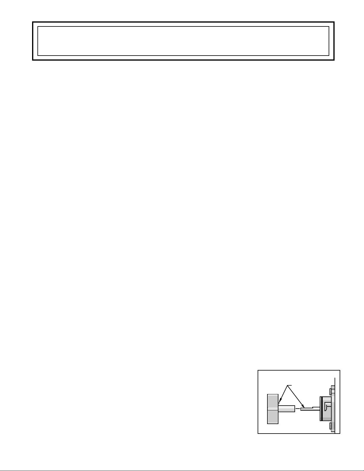
REMOVING AND CLEANING THE WHIPPER CHAMBERS*
1. Start by taking off the upper mixing cup. Pull it forward, twist to the left and lift
up to separate from the lower mixing cup.
2. Take off the lower mixing cup by pulling it up and for
ward to free it from the hot water inlet fitting.
LINE UP TICK MARK
WITH FLAT ON
MOTOR SHAFT
3. Pull the dispensing nozzle from the whipper chamber.
4. Take hold of the whipper chamber and turn clockwise to
free it from the mounting plate. Remove it from the unit.
5. Pull the whipper propeller from the motor shaft. When re assembling, make sure the propeller is properly aligned
and seated on the motor shaft (fig 5.). Failure to push
Figure 5. Prop Alignment
*For easy access remove all canisters.
[ 4 ]
Page 6

Cleaning & Maintenance (Continued)
0
0
0
5
5
5
5
propeller in all the way will cause the propeller to fuse with the whipper chamber.
6. Twist the mounting plate clockwise and pull it off the motor shaft (#9, Fig. 9.).
7. Pull off the O' ring from the mounting plate (#10, Fig. 9.).
8 . Clean all the parts with a mild dishwashing liquid. Thoroughly clean inside the dis-
pensing nozzle. Rinse off the parts before re-assembling.
9. Assemble components.
EVERY SIX MONTHS
The inside of the heating tank should be de-limed periodically, more often in areas with
extremely hard water. The de-liming procedure must be performed by a qualified service
technician.
Side Panel Removal
The left side panel of Primo Cappuccino machines can be removed
easily by taking the following steps:
CAUTION Disconnect electrical power while performing
these steps.
1. Open the front door. Remove the top cover by taking out
the screws holding it to the top of the side panels. Slide the top
cover forward to remove.
On some models a screw centered in the front of the top
cover must also be loosened
2. Remove the screw holding the spout shield to inside the
left or right side panel (PC-3 only), lower arrow.
3. Take hold of the top edge of the panel, lift up and off.
NOTE If removing the right side panel, care must be taken to support
the front door. The wires that run to the controls in the door will still be
23456789
234
23456789
234
23456789
234
234
LIFTLIFT
LIFT
LIFTLIFT
UPUP
UP
UPUP
PANELPANEL
PANEL
PANELPANEL
SCREWSCREW
SCREW
SCREWSCREW
HEADHEAD
HEAD
HEADHEAD
INSIDEINSIDE
INSIDE
INSIDEINSIDE
PANELPANEL
PANEL
PANELPANEL
FRAMEFRAME
FRAME
FRAMEFRAME
KEY-KEY-
KEY-
KEY-KEYHOLEHOLE
HOLE
HOLEHOLE
ONON
ON
ONON
FRAMEFRAME
FRAME
FRAMEFRAME
Figure 6. Detail of
Fastener on Panel.
connected to the components in the frame.
Figure 7. Screw
Location.
Troubleshooting
ALL IN WARRANTY SERVICE SHOULD BE PERFORMED BY AN AUTHORIZED SERVICE TECHNICIAN
The Primo Cappuccino units are simple machines to service. This Troubleshooting guide will
cover most questions you may have about problems you can encounter with the machine. If
you find that you cannot remedy a problem on your machine, you may call our factory service department at (213) 269-8121, extension 3001.
[ 5 ]
Page 7

Troubleshooting (Continued)
WARNING As with all electrical equipment, caution must be taken to avoid electrical
shock. Be sure power cord is disconnected before removing components.
The following steps will also involve working with hot water. Scalding may occur if care
is not taken to avoid spilling hot water.
1 . PROBLEM: Water does not flow into heating tank
POSSIBLE CAUSE
Water line turned off or
filter clogged up.
Grounded probe, WC-5502.
Defective or burned out
liquid level control board,
WC-608.
SOLUTION
Disconnect the water line from the inlet valve and check the
water pressure. Reopen the water line. Replace the filter
cartridge and remove any obstruction.
Whenever the water level in the tank drops below the probe
tip, the water inlet valve should open to fill the tank. If the
water level is too low, check to see if the probe is grounded.
Pull the wire terminal off the terminal on the probe. If water
begins to flow into the tank, this indicates that the probe
has shorted. Clean up the probe thoroughly and reinstall it. If
condition persists, replace it with a new probe. Wrap probe
wire with Teflon tape if there is an indication of excessive
condensation. Leave 1/8" of the probe exposed.
If the probe is not grounded, check the operation of the
liquid level control board (L.L.C.).
Measure the voltage at the input terminals T2 and T3 of
the L.L.C.. Your voltmeter should read approximately 115
volts. It should also read 115 volts at the output terminals
T1 & T3 (this output supplies power to the valve coil).
Lacking voltage at terminals T1 & T3 will indicate that the
L.L.C. is malfunctioning. All wire connections to the board
should be tight. Make sure there is contact between the
grounding plate on the back side of the L.L.C. and its mounting bracket.
Faulty water inlet valve coil
Valve Part No. WC-826.
CAUTION Do not turn water supply off while the power is on. Damage to the coil on
the water inlet valve will result.
To check the water inlet valve, the water level must be
below the probe, the machine on and plugged in. With a
voltmeter, check for voltage to the valve coil. If there is
power to the coil and no water is flowing, the coil or valve
must be replaced.
[ 6 ]
Page 8

Troubleshooting (Continued)
2 . PROBLEM: Water level in the heating tank too high. Tank is overflowing.
POSSIBLE CAUSE
Torn diaphragm or lime build
up in the water inlet valve
Lime build up on the water
level probe
A break in the probe circuit
3 . PROBLEM: Low temperature or cold water in the heating tank.
Remove the top cover of the heating tank and check the
water level. Switch off the power using the toggle switch
behind the machine. If water continues to flow into the
tank, the valve is leaking.
Clean, rebuild or replace the valve.
Pull off the wire with terminal from the water level probe.
Touch the terminal end of the wire to the steel body of the
heating tank. If the water flow stops, this is an indication
that the probe is probably limed up or has lost its continuity
to the solid state L.L.C. board. Clean probe or look for a
break in the circuit and repair it.
When the probe is submerged in water, there should not be
voltage present at the terminals of the inlet valve. Check for
broken or loose wire connections.
SOLUTION
POSSIBLE CAUSE
Thermostat is turned off
Faulty Thermostat
Burned out heating element
SOLUTION
Check to see that the thermostat is turned on. Twist the
stem clockwise as far as it will go.
With the thermostat turned fully clockwise, turn the power
on, observe and measure the water temperature at the
instant the thermostat switches off (brew light on). If the
temperature is too low, replace the thermostat.
Read the current with a clamp ammeter on one of the two
14 gauge wires connected to the element. Turn on the
machine. The meter should read approximately 16 amperes. If you cannot get a reading, use a voltmeter to
check for voltage across the heating element terminals. If
there is ~115 volts, the element is burned out.
[ 7 ]
Page 9

AA
AA
A
DETAIL DETAIL
DETAIL DETAIL
6
7
DETAIL
Fig. 9. Whipper Motor & CanisterFig. 8. Main View, Primo Cappuccino
Illustrated Parts List
3
1
4
5
2
Illustrated Parts List
[ 8 ]
Page 10

REFREF
REFREF
REF
CC
CC
C
DETAIL DETAIL
DETAIL DETAIL
DETAIL
Fig. 11. Frame, PC-3Fig. 10. Door, PC-3
Illustrated Parts List
BB
BB
B
DETAIL DETAIL
DETAIL DETAIL
DETAIL
Illustrated Parts List
Shown.
Door, PC-1
[ 9 ]
Page 11

Illustrated Parts List
DETAIL D
Fig. 12. Heating Tank
[ 10 ]
Page 12

Parts List, PC-1, PC-2 & PC-3, PC-4 & HC-1
IndexIndex
IndexIndex
Index
IndexIndex
NN
Nº
NN
1A
1B
1C
2A
2B
2C
3A
3B
4A
4B
4C
4D
4E
5A
5B
6
7
8
9
10
11
12
13
14
15
16
17A
17B
18
19
20
21
22
23
24A
24B
24C
24D
25A
25B
26A
26B
26C
27A
27B
Part NPart N
Part Nº
Part NPart N
WC-6673
WC-6755
WC-6853
WC-6633
WC-6758
WC-6848
WC-6644
WC-6768-BLK
WC-6645
WC-6747-BLK
WC-6746-BLK
WC-6842
WC-6843
WC-6643
WC-6744-BLK
CA-1011-03
WC-43033
WC-3739
CA-1010-05
CA-1008-03
CA-1006-03
CA-1037
CA-1009-03
CA-1005-03
CA-1026-03
CA-1065
CA-1000
CA-1050
CA-1001
CA-1002
CA-1041
CA-1042
WC-37054
WC- 152
WC-6639
WC-6767
WC-6766
WC-6840
CA-1022
CA-1060
CA-1023-01
CA-1061 -01
CA-1071 -01
CA-1021
CA-1059
DescriptionDescription
Description
DescriptionDescription
Drawer, Drip,
Drawer, Drip,
Drawer, Drip,
Screen, Drip Drawer,
Screen, Drip Drawer,
Screen, Drip Drawer,
Panel, Right Side,
Panel, Right Side,
Cover, Top,
Cover, Top Front,
Cover, Top Back,
Cover, Top Front,
Cover, Top Back,
Panel, Left Side,
Panel, Left Side,
Bulkhead Water Fitting
O' Ring . . . . . . . . . . . . . . . . . . . . . . . . . . .
Kit, Motor Whipper Assy . . . . . . . . . . . . . . . . . . .
Plate, Whipper Chamber Assy W/Resin Seal . . . . . . .
Propeller, Whipper . . . . . . . . . . . . . . . . . . .
Chamber, Whipper . . . . . . . . . . . . . . . . . . .
Nozzle, Dispensing . . . . . . . . . . . . . . . . . . .
Bowl, Mixing . . . . . . . . . . . . . . . . . . . . . . .
Trap, Steam . . . . . . . . . . . . . . . . . . . . . . .
Elbow, Ingredient Chute . . . . . . . . . . . . . . .
Bushing, Discharge . . . . . . . . . . . . . . . . . .
Canister Assembly, 4 Lb.,
Canister Assembly, 6 Lb.,
Canister Only,
Lid, Canister,
Wheel, Agitation,
Auger, 6.7 cc/sec . . . . . . . . . . . . . . . . . . .
Kit, Socket Gear . . . . . . . . . . . . . . . . .
Switch, Push Button . . . . . . . . . . . . . . . .
Door, Front Only,
Door, Front Only,
Door, Front Only,
Door, Front Only
Window, Outer, Clear,
Window, Outer, Clear,
Film, Std Curtis Logo
Film Graphic, Curtis Logo,
Film Graphic, Curtis Logo,
Window, Inner, Clear,
Window, Inner, Clear,
PC-3PC-3
PC-3 . . . . . . . . . . . . . . . . .
PC-3PC-3
PC-1, PC-2, HC-1 PC-1, PC-2, HC-1
PC-1, PC-2, HC-1 . . . . . . . .
PC-1, PC-2, HC-1 PC-1, PC-2, HC-1
PC-4PC-4
PC-4 . . . . . . . . . . . . . . . . . .
PC-4PC-4
PC-3 PC-3
PC-3 . . . . . . . . . . . .
PC-3 PC-3
PC-1, PC-2, HC-1 PC-1, PC-2, HC-1
PC-1, PC-2, HC-1 . .
PC-1, PC-2, HC-1 PC-1, PC-2, HC-1
PC-4PC-4
PC-4 . . . . . . . . . . . .
PC-4PC-4
PC-3 PC-3
PC-4 PC-4
PC-3,
PC-4 . . . . . . . . .
PC-3 PC-3
PC-4 PC-4
PC-1, PC-2, HC-1 PC-1, PC-2, HC-1
PC-1, PC-2, HC-1 . . . . .
PC-1, PC-2, HC-1 PC-1, PC-2, HC-1
PC-3 PC-3
PC-3 . . . . . . . . . . . . . . . . . .
PC-3 PC-3
PC-1, PC-2, HC-1PC-1, PC-2, HC-1
PC-1, PC-2, HC-1 . . . . .
PC-1, PC-2, HC-1PC-1, PC-2, HC-1
PC-1, PC-2, HC-1PC-1, PC-2, HC-1
PC-1, PC-2, HC-1 . . . . .
PC-1, PC-2, HC-1PC-1, PC-2, HC-1
PC-4PC-4
PC-4 . . . . . . . . . . . . . . .
PC-4PC-4
PC-4PC-4
PC-4 . . . . . . . . . . . . . . .
PC-4PC-4
PC-3 PC-3
PC-4 PC-4
PC-3,
PC-4 . . . . . . . . . .
PC-3 PC-3
PC-4 PC-4
PC-1, PC-2, HC-1PC-1, PC-2, HC-1
PC-1, PC-2, HC-1 . . . . . .
PC-1, PC-2, HC-1PC-1, PC-2, HC-1
PC, CK, HCPC, CK, HC
PC, CK, HC. . . . . . . . . . .
PC, CK, HCPC, CK, HC
PC-2, PC-3, PC4PC-2, PC-3, PC4
PC-2, PC-3, PC4
PC-2, PC-3, PC4PC-2, PC-3, PC4
PC-1, HC-1 PC-1, HC-1
PC-1, HC-1 . . . .
PC-1, HC-1 PC-1, HC-1
PC-2, PC-3, PC4 PC-2, PC-3, PC4
PC-2, PC-3, PC4 . . . . . . . .
PC-2, PC-3, PC4 PC-2, PC-3, PC4
PC-2 & PC-3, PC4 PC-2 & PC-3, PC4
PC-2 & PC-3, PC4 . . . . . . .
PC-2 & PC-3, PC4 PC-2 & PC-3, PC4
PC-2, PC-3, PC4 PC-2, PC-3, PC4
PC-2, PC-3, PC4 . . . . . .
PC-2, PC-3, PC4 PC-2, PC-3, PC4
PC-3 PC-3
PC-3 . . . . . . . . . . . . . .
PC-3 PC-3
PC-2 PC-2
PC-2 . . . . . . . . . . . . . . .
PC-2 PC-2
PC-1 & HC-1 PC-1 & HC-1
PC-1 & HC-1 . . . . . . . .
PC-1 & HC-1 PC-1 & HC-1
, PC4, PC4
, PC4 . . . . . . . . . . . . . . . .
, PC4, PC4
PC-3, PC4 PC-3, PC4
PC-3, PC4 . . . . .
PC-3, PC4 PC-3, PC4
PC-1, PC-2, HC-1 . PC-1, PC-2, HC-1 .
PC-1, PC-2, HC-1 .
PC-1, PC-2, HC-1 . PC-1, PC-2, HC-1 .
PC-3, PC4 PC-3, PC4
PC-3, PC4 . . . . . . . . . . . .
PC-3, PC4 PC-3, PC4
PC-1 & PC-2 PC-1 & PC-2
PC-1 & PC-2 . .
PC-1 & PC-2 PC-1 & PC-2
HC-1 HC-1
HC-1 . . . . . . . .
HC-1 HC-1
PC-3, PC4 PC-3, PC4
PC-3, PC4 . . . . . .
PC-3, PC4 PC-3, PC4
PC-1, PC-2, HC-1 PC-1, PC-2, HC-1
PC-1, PC-2, HC-1 . .
PC-1, PC-2, HC-1 PC-1, PC-2, HC-1
[ 11 ]
Index
IndexIndex
NN
Nº
NN
28
29
30
31
32
33A
33B
34
35
36
37
38
39
40A
40B
40C
40D
41A
41B
41C
42
43
44A
44B
45
46
47
48
49
50
51
52
53
56
57
58
59
60
61A
61B
62
63
64
65
Part NPart N
Part Nº
Part NPart N
CA-1015
CA-1020
CA-1017
WC-5930
WC-4426
WC-6635
WC-6751
CA-1018
CA-1016
WC-4201
WC- 608
WC-4380
WC- 435
WC-6615
WC-6763
WC-6754
WC-6839
WC-6670
WC-6756
WC-6839
CA-1013
CA-1036
WC-6636
WC-6879
CA-1030
WC- 518
WC- 102
WC-1200
WC-1408
WC-2401
WC-4425
WC-43019
WC- 826
WC-37123
WC-3503
WC-6637
WC-4440
CA-1024-03
WC-6616
WC-6677
WC- 202
WC- 101
WC-4320
WC-4211
DescriptionDescription
Description
DescriptionDescription
Transformer . . . . . . . . . . . . . . . . . . . . . . .
Starter, Fluorecent Lamp . . . . . . . . . . . . . .
Socket, Starter Base . . . . . . . . . . . . . . . . .
Panel, Weld Assy. Door . . . . . . . . . . . . . . .
Screw, 8-32 X 3/8 Phillips . . . . . . . . . . . . .
PC-3PC-3
Box, Light,
Panel, Back,
Lamp, Fluorecent . . . . . . . . . . . . . . . . . . . .
Holder, Fluorecent Lamp . . . . . . . . . . . . . . .
Nut, Hex Kep . . . . . . . . . . . . . . . . . . . . . .
Liquid Level Control . . . . . . . . . . . . . . . . . .
Guard, Shock . . . . . . . . . . . . . . . . . . . . . .
Relay, 120V . . . . . . . . . . . . . . . . . . . . . . .
Shelf, Canister,
Shelf, Canister,
Shelf, Canister,
Shelf, Canister,
Cover, Dump Valve,
Cover, Dump Valve,
Cover, Dump Valve,
Motor, Gear . . . . . . . . . . . . . . . . . . . . . . .
Gear, Plastic Auger . . . . . . . . . . . . . . . . . .
Plenum, Exhaust,
Plenum, Exhaust,
Hose, 18", Air . . . . . . . . . . . . . . . . . . . . .
Thermostat . . . . . . . . . . . . . . . . . . . . . . . .
Switch, Toggle . . . . . . . . . . . . . . . . . . . . .
Power Cord, 120V . . . . . . . . . . . . . . . . . .
Grip, Cord . . . . . . . . . . . . . . . . . . . . . . . .
Elbow, 3/8 x 1/4 Flare . . . . . . . . . . . . . . . .
Bolt, 3/8-16 x 5/8 . . . . . . . . . . . . . . . . . . .
Washer,Split Lock . . . . . . . . . . . . . . . . . . .
Valve, S53 Water Inlet . . . . . . . . . . . . . . . .
Fan, Extract . . . . . . . . . . . . . . . . . . . . . . .
Bumper Leg . . . . . . . . . . . . . . . . . . . . . . .
Base, Bottom . . . . . . . . . . . . . . . . . . . . . .
Screw, 8-32 x ¾ L Phillip . . . . . . . . . . .
Pillar, Mounting Plate . . . . . . . . . . . . . . . . .
Shield,
, PC-4, PC-4
Shield
, PC-4 . . . . . . . . . . . . . . . . . . . . . . .
, PC-4, PC-4
Brew Light 115V . . . . . . . . . . . . . . . . . . . .
Switch, Wash Cycle . . . . . . . . . . . . . . . . . .
O' Ring,
Nut, Jam,
PC-4PC-4
PC-3,
PC-4 . . . . . . . . . . . . . . .
PC-3PC-3
PC-4PC-4
PC-1, PC-2, HC-1PC-1, PC-2, HC-1
PC-1, PC-2, HC-1 . . . . . . . . .
PC-1, PC-2, HC-1PC-1, PC-2, HC-1
PC-3PC-3
PC-3 . . . . . . . . . . . . . .
PC-3PC-3
PC-2PC-2
PC-2 . . . . . . . . . . . . . .
PC-2PC-2
PC-1PC-1
PC-1 . . . . . . . . . . . . . .
PC-1PC-1
PC-4PC-4
PC-4 . . . . . . . . . . . . . . . .
PC-4PC-4
PC-3PC-3
PC-3 . . . . . . . . . . . . .
PC-3PC-3
PC-1, PC-2, HC-1 . .PC-1, PC-2, HC-1 . .
PC-1, PC-2, HC-1 . .
PC-1, PC-2, HC-1 . .PC-1, PC-2, HC-1 . .
PC-4PC-4
PC-4 . . . . . . . . . . . . .
PC-4PC-4
PC-3PC-3
PC-3 . . . . . . . . . . . . .
PC-3PC-3
PC-4PC-4
PC-4 . . . . . . . . . . . . . . .
PC-4PC-4
PC-3PC-3
PC-3 . . . . . . . . . . . . . . . . . . . . . . .
PC-3PC-3
PC-3, PC-4PC-3, PC-4
PC-3, PC-4 . . . . . . . . . . . . . . . . .
PC-3, PC-4PC-3, PC-4
PC-3, PC-4PC-3, PC-4
PC-3, PC-4 . . . . . . . . . . . . . . . .
PC-3, PC-4PC-3, PC-4
Page 13

Parts List, PC-1, PC-2 & PC-3, PC-4 & HC-1
IndexIndex
Index
IndexIndex
Index
IndexIndex
NN
Nº
NN
66A
66B
66C
66D
67
68
69
70
71
72
74
75
76
77
78
79
Part NPart N
Part Nº
Part NPart N
CA-1034
CA-1057
CA-1055
WC-54074
WC-2938
WC-5502
WC-29009
WC-4306
WC-29010
WC-4394
WC- 904
WC-4506
WC-6654
WC-3688
WC-4212
WC-29006
DescriptionDescription
Description
DescriptionDescription
Heating Tank W/Fittings Only,
Heating Tank W/Fittings Only,
Heating Tank W/Fittings Only,
Heating Tank W/Fittings Only,
Fitting, Probe . . . . . . . . . . . . . . . . . . . . . .
Probe, LLC . . . . . . . . . . . . . . . . . . . . . . . .
Fitting, Inlet . . . . . . . . . . . . . . . . . . . . . . .
Washer, 9/16 I.D. Teflon . . . . . . . . . . . . . .
Fitting, Overflow . . . . . . . . . . . . . . . . . . . .
Guard, Shock for Heating Elements . . . . . . .
Heating Element, 1600W, 120V . . . . . . . . . . .
Screw, 8-32 x 5/8, Slotted . . . . . . . . . . . . . .
Lid, Heating Tank . . . . . . . . . . . . . . . . . . . . .
Insulation, Wrap
Nut, 5/8" Jam . . . . . . . . . . . . . . . . . . . . . . .
Fitting, Dump Valve . . . . . . . . . . . . . . . . . . . .
PC-3 & PC-4PC-3 & PC-4
PC-3 & PC-4 . . . . . . . . . . . . . . . .
PC-3 & PC-4PC-3 & PC-4
PC-3 PC-3
PC-3 . . . . . .
PC-3 PC-3
PC-2PC-2
PC-2 . . . . . .
PC-2PC-2
PC-1 & HC-1PC-1 & HC-1
PC-1 & HC-1
PC-1 & HC-1PC-1 & HC-1
PC-4PC-4
PC-4 . . . . . . . .
PC-4PC-4
IndexIndex
NN
Nº
NN
80
81
82
83A
83B
83C
83D
84
89
90
91
92A
92B
92C
92D
93
Part NPart N
Part Nº
Part NPart N
CA-1039
WC- 880E
WC-43062
CA-1035
CA-1058
CA-1056
WC-54073
WC-3734
WC-4501
WC-39105
WC-39107
WC-39106
WC-39120
WC-39116
WC-39205
CA-1027
DescriptionDescription
Description
DescriptionDescription
O' Ring, Cappuccino Dump Valve . . . . . . . . . . .
Valve, Adjustable Dump . . . . . . . . . . . . . . . . .
Gasket, Silicone . . . . . . . . . . . . . . . . . . . . . . .
Heating Tank Complete,
Heating Tank Complete,
Heating Tank Complete,
Heating Tank Complete,
Kit, Rpl Deltrol Dump Valve PC . . . . . . . . . . . .
Screw, 8-32 x 1/4, Slotted . . . . . . . . . . . . . . . .
Label, Flavor, Static Cling . . . . . . . . . . . . . . . . .
Label, Flavor, Adhesive Backed . . . . . . . . . . . . .
Label, Splash Panel,
Label, Splash Panel,
Label, Splash Panel,
Label, Splash Panel,
Label, Prevent Overflow . . . . . . . . . . . . . . . . . .
PC-3PC-3
PC-3 . . . . . . . . . . . .
PC-3PC-3
PC-2 PC-2
PC-2 . . . . . . . . . . . .
PC-2 PC-2
PC-1 & HC-1PC-1 & HC-1
PC-1 & HC-1 . . . . .
PC-1 & HC-1PC-1 & HC-1
PC-4PC-4
PC-4 . . . . . . . . . . . . . .
PC-4PC-4
PC-3PC-3
PC-3 . . . . . . . . . . . . . . . . .
PC-3PC-3
PC-2PC-2
PC-2 . . . . . . . . . . . . . . . . .
PC-2PC-2
PC-1 & HC-1PC-1 & HC-1
PC-1 & HC-1 . . . . . . . . . . .
PC-1 & HC-1PC-1 & HC-1
PC-4PC-4
PC-4 . . . . . . . . . . . . . . . . .
PC-4PC-4
[ 12 ]
Page 14

[ 13 ]
Page 15

[ 14 ]
Page 16

WARRANTY
We hereby certify that the products manufactured by the Wilbur Curtis Company, Inc., are, to thebest of our knowledge,
free from all defects and faulty workmanship.
The following warranties and conditions are applicable:
1. 1 Year Parts & Labor from Date of Purchase from Factory: This warranty covers all electrical parts, fittings
and tubing.
2. 40 Months or 40, 000 Pounds of Coffee on a set of Grinding Burrs. (ADS Grinders)
3. 3 Years from Date of Purchase: This warranty covers electronic control boards and leaking or pitting of a
stainless steel body of a Brewer or Urn.
4. 90 Days from Date of Purchase: On replacement parts that have been installed on out of warranty equipment
All in-warranty service calls must have prior authorization from the manufacturer. For an RMA (Return Merchandise
Authorization) number, call the Technical Service Department at 1-800-995-0417. The Wilbur Curtis Company will allow
up to 100 miles, round trip, per in-warranty service call.
CONDITIONS & EXCEPTIONS
The warranty covers original equipment at time of purchase only. The Wilbur Curtis Company, Inc., assumes no
responsibility for substitute replacement parts installed on Curtis equipment that have not been purchased from the
Wilbur Curtis Company. Inc The Wilbur Curtis Company will not accept any responsibility if the following conditions are not
met. The warranty does not cover and is void under these circumstances:
1) Improper operation of equipment. The equipment must be used for its designed and intended
purpose and function.
2) Improper installation of equipment. This equipment must be installed by a professional,
certified technician and must comply with all local electrical, mechanical and plumbing codes.
3) Wilbur Curtis Company will not be responsible for the operation of equipment at other than the
stated voltages on the serial plate.
4) Abuse or neglect (including failure to periodically clean or remove lime accumulations).
Manufacturer is not responsible for variation in equipment operation due to excessive lime or
local water conditions.
5) Replacement of items subject to normal use and wear. This shall include, but is not limited to,
light bulbs, shear disks, “0” rings, gaskets, canister assemblies. whipper chambers and plates,
mixing bowls, agitation assemblies and whipper propellers.
6) Any faults resulting from inadequate water supply. This includes, but is not limited to, excessive or low water pressure, and inadequate or fluctuating water flow rate.
7) All repairs and/or replacements are subject to our decision that the workmanship or parts were
faulty and the defects showed up under normal use.
8) All labor shall be performed during regular working hours. Overtime charges are the responsibility of the owner.
9) Charges incurred by delays, waiting time, or operating restrictions that hinder the service
technician’s ability to perform service is the responsibility of the owner of the equipment.
This includes institutional and correctional facilities.
10) All claims under this warranty must be submitted to the Wilbur Curtis Company Technical
Service Department before return of the unit to the factory.
11) All equipment returned to us must be repackaged properly in the original carton. No units will
be accepted if they are damaged in transit due to improper packaging.
12) Damaged in transit.
13) The resetting of safety thermostats and circuit breakers, programming and temperature
adjustments are the responsibility of the equipment owner.
11.0 . ECN6052 . F-2043_revA.p65X
NO UNITS OR PARTS WILL BE ACCEPTED WITHOUT A RETURN MERCHANDISE AUTHORIZATION (RMA).
RMA NUMBER MUST BE MARKED ON THE CARTON OR SHIPPING LABEL.
All in-warranty service calls must be performed by an authorized service center, where service is available. Call the factory
for location near you.
WILBUR CURTIS CO., INC.
6913 Acco St., Montebello, CA 90640-5403 USA
Phone: 800/421-6150
Technical Support Phone: 800/995-0417 (M-F 5:30A - 4:00P PST) E-Mail: techsupport@wilburcurtis.com
Web Site: www.wilburcurtis.com
FOR THE LATEST SPECIFICATION INFORMATION GO TO WWW.WILBURCURTIS.COM
Fax: 323-837-2410
Printed in U.S.A. 8/03 F-2043 revA
 Loading...