

Page 1
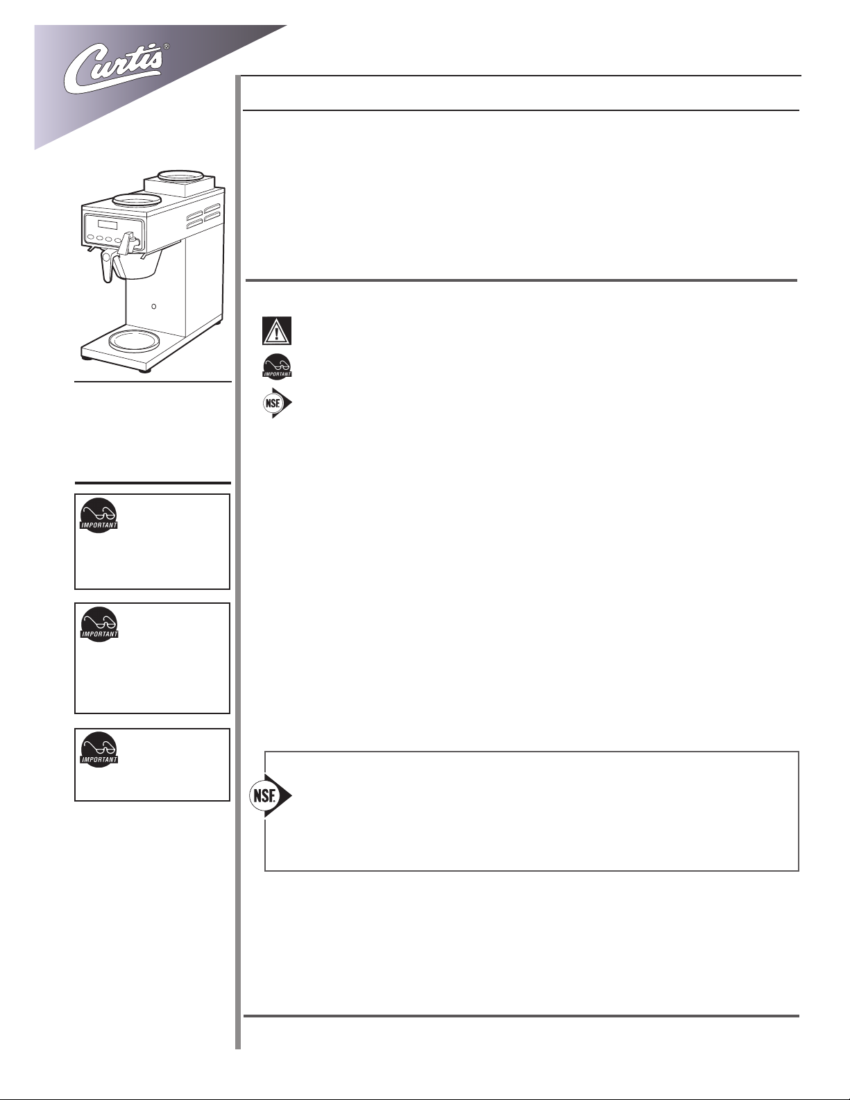
Wilbur Curtis Company, inC.
Service Manual – ALPGT Fresh-Trac
Important Safeguards/Conventions
This appliance is designed for commercial use. Any servicing other than cleaning and preventive maintenance
should be performed by an authorized Wilbur Curtis service technician.
• Do NOT immerse the unit in water or any other liquid
• To reduce the risk of re or electric shock, do NOT open service panels. No user serviceable parts inside.
• Keep hands and other items away from hot surfaces of unit during operation.
• Never clean with scouring powders, bleach or harsh chemicals.
Symbols
WARNINGS – To help avoid personal injury
Important Notes/Cautions – from the factory
Models Included:
• ALPHA 3GT Fresh-Trac
• ALPHA 6GTN Fresh-Trac
CAUTION:
Equipment must be
installed to comply
with applicable federal, state,
and local plumbing/electrical
codes.
CAUTION: Follow
this setup procedure
before attempting
to use this unit. Failure to
follow these instructions can
result in injury and/or void of
warranty.
CAUTION: DO NOT
connect the unit to
hot water supply.
The inlet valve is not rated for
hot water.
Sanitation Requirements
The Curtis Alpha GT is Factory Pre-Set and Ready to Go… Right from the Box.
Following are the Factory Settings for the Alpha Fresh-Trac:
• Brew Temperature = 200°F
• Brew Volume = Set to vessel requirements (60 oz).
System Requirements:
• Water Source 20 – 90 PSI (minimum ow rate of ½ GPM)
• Electrical: See attached schematic for standard model or visit www.wilburcurtis.com for your model.
SETUP STEPS
1. The unit should be level (left to right - front to back), on a secure surface.
2. Connect the water line to the water inlet tting on the rear of the unit. Water volume ow to the machine
should be consistent. Use tubing sized sufciently to provide a minimum ow rate of ½ gallon per minute
(1 gallon per minute preferred).
NOTE: A water ltration system must be used to help maintain trouble-free operation. Air must be
purged from the cartridge prior to connection to equipment. In areas with extremely hard water,
we recommend the use of a Curtis approved water lter. For our full line of lters, please log on to www.
wilburcurtis.com.
NSF International requires the following water connection:
1. A quick disconnect or additional coiled tubing (at least 2x the depth of the unit) is required so
that the unit can be moved for cleaning.
2. Thisunitmustbeinstalledwithadequatebackowprotectiontocomplywithapplicablefederal,
state and local codes.
3.Waterpipeconnectionsandxturesdirectlyconnectedtoaportablewatersupplyshallbe
sized,installedandmaintainedinaccordancewithfederal,state,andlocalcodes.
ISO 9001:2008 REGISTERED
WILBUR CURTIS CO., INC.
6913 West Acco Street
Montebello, CA 90640-5403
For the latest information go to
www.wilburcurtis.com
Tel: 800-421-6150
Fax: 323-837-2410
3. Connect the unit to electrical outlet with appropriate amperage rating (see serial tag on machine).
4. Once power has been supplied to the unit, ip the toggle switch to the ‘ON’ position (located on the rear of
the unit), the water tank will begin to ll. When the water level in the tank reaches the probe, the heating
element(s) will turn on.
5. Water in the heating tank will require approximately a half hour before reaching operating temperature (factory
setting of 200°F). Where applicable, turn on the Universal Control Module (UCM). When the unit reaches
operating temperature, it will display “READY TO BREW”..
Technical Support: 1-800-995-0417 M-F 5:30am-4:00pm PT
Email: techsupport@wilburcurtis.com
1
Page 2
Your Curtis G3 System is Factory Pre-Set for Optimum Performance.
After connection to water and power; the rear toggle switch must be on. You will hear a beep sound, indicating power
is available to the controller.
The control displays . Press ON/OFF button and the screen will display . After three
seconds is displayed.
Water will ll the tank (approximately 2-3 minutes depending on water ow rate). When the proper level is reached
will appear on the screen. It takes approximately 20 minutes to reach setpoint temperature of 200°F.
Control will display when temperature reaches the setpoint (200°F). Unit is now ready to brew.
BREWING INSTRUCTIONS
1. Brewer should be ON. Conrm this at the rear toggle switch. Press the ON/OFF button on the UCM control panel.
Ready-to-Brew should be displayed.
2. Place an empty decanter on the warmer plate.
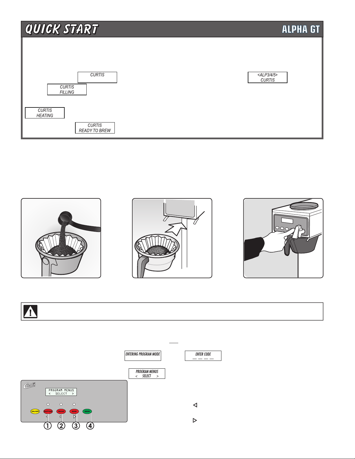
3. Place a paper lter into the brewcone.
4. Pour ground coffee into the
new lter.
WARNING TO AVOID SCALDING, Do not remove the brewcone or coffee container until the UCM screen indicates that the brew
cycle has nished.
5. Position brewcone nto
brew rails.
6. Press Brew button to start
the brew cycle.
To Go Into Programming
Turn off (dark display) by pressing ON/OFF button (yellow). Press and hold BREW button (green) and then press and release ON/OFF button
(yellow).
Continue holding BREW button. Display will read , wait until is displayed Enter the 4-digit access code, the
digits 1-4 correspond to the buttons (see illustration below).
The default code set at the factory is 1-2-3-4. Then will be displayed.
All programming selections are performed with the three center
buttons.
The symbols below the buttons are:
Scroll LEFT
SELECTION or ENTER to save new parameter
Scroll RIGHT
2
Page 3
PROGRAM MENUS
Model Select – Always perform this rst. This feature re-sets all settings to the factory defaults.
Scroll through the menu to Model Select. The choices are ALPHA-1, ALPHA-2, ALPHA-3/4/5, and Thermo-Alpha. For Fresh-Trac
models, select ALPHA-2 or ALPHA-3/4/5.
Brew Volume
Selecting Brew by Volume or Brew by Time depends on whether you know your brew time before starting. From Program Menus press >
display will now show the next feature.
During the actual brew cycle, a 2-minute drip mode is added to the brew time. The programmed water level compensates for back to
back brewing to allow for an increase of water volume.
Brew by Volume (Factory set to 60 oz.): Press to Select, Display will now show Push START To Begin... Press the BREW button then hot
water starts running, when desired volume is reached press BREW button again to stop the ow. Now the volume has been set. Pressing > button will display the subsequent menu features.
Brew by Time (Factory set to 2min–20sec). Press to Select to change the brew time. Display will now show the current time. By pressing <
or > you can toggle back and forth from minutes to seconds to exit (EX). Change the time or set and exit by pressing .
Temperature (Factory set to 200°F) Press to Select. Press < or > to move to desired temperature and then to set. Temperature is
programmable from 170ºF to 206ºF, in 2-degree increments.
Energy Save Mode (Factory set to OFF) Press to Select, < or > ON, OFF or ON 140ºF , to set. When in ON, unit will automatically shut
off 4 hours from last brew. When feature is OFF, unit does not have the energy saving mode. In the ON 140ºF position, temperature goes down
to 140ºF. if unit has not brewed in 4 hours. This feature will save energy by lowering the tank temperature during periods of non-operation.
Brew Count Odom Press to display total gallons brewed. Press ex or Reset
Pre-Infusion (Factory set to OFF) Press to Select. Current setting in seconds is displayed < to decrease or select > to increase. The
range is from OFF to 10 through 60 seconds, in 10 second increments. Press to set.
If Pre-infusion is selected (ON), Cold Brew Lock is set to within 15ºF of set point and Cold Brew Lock disappears from the list of program selections. When Pre-infusion is ON, Pulse Brew disappears from the list of program selections.
Quality Timer (Factory set to OFF) Press to Select. Press < or > to move to OFF, ON, or a range from 20 Min to 120 Min in 10 minute
increments. Press to set.
Brew Count Total Press to Select, Shows total gallons and total brew cycles on the unit. Is read only and not resettable.
Cold Brew Lock (Factory set to 15º) Press to select, < or > to select desired setting (CBL 5 or 15), to set.
The Cold Brew Lock feature allows the brewer to brew at three different temperature levels from the actual set point. The rst setting is within
5 degrees of set point, next is within 15 degrees of set point for the Ready to Brew message, however it will brew at any temperature.
Master Reset Press to display Are You Sure? Then < for Yes, > for No. Brewer factory defaults are then reset.
Service Call (Phone number Factory set to 1-[800] 000-0000x) Press to display number and change number or < to move place and EX to
exit when complete This number will be displayed during a Heating system SENSOR ERROR or during a WATER ERROR.
Access Code (Factory set to 1-2-3-4) Press to display number and change number, (the range is 1 to 4) or < to move place and ex to exit
when complete.
Banner Name (Factory set to CURTIS) Press to display letters and change letters or < to move place and EX to exit when complete. This
feature allows up to 14 letters to be programmed for company name or regional name. Programming all blanks disables Banner Name.
Warmer Auto OFF (Factory set to Disable) Press to Select. Press < or > to move to desired time and then to set. Timer range is OFF, 2
hours, 3 hours, and 4 hours.
P-Maintenance (Factory set to OFF) Press to select. To turn on, press < or > set gallons brewed. The range is from Off to 3000 gallons.
Press to exit. When the number of brews reaches the set amount, P-Maintenance will display on the screen.
Beeper On/Off (Factory set to ON) Press to display ON or OFF. Pressing either < or > to toggle between on and off. Press to set.
Pulse Brew (Factory set to OFF). Press to select, < or > to select OFF or one of ve pulse patterns (A to E).
This feature allows tuning of the coffee avor. The pot level should always be set rst with this option OFF. Depending on your grind prole and
water conditions, the ve Pulse Brew options help “tune” or change the coffee avor.
Pulse Brew continued on page 4 . . .
3
Page 4
PROGRAM MENUS
Guidelines for Pulse Brew:
Filter Pack type coffees characteristically extract better with the A and B pulse setting. Decaffeinated coffees normally extract better with the
B pulse setting. High-Yield coffees typically extract better with the C pulse setting. The A, B or C settings may be satisfactory to go well with
your coffee variety or taste prole. There are two additional settings (D and E) that allow you to manually set the ON time pulses and OFF time
pulses.
If Pulse Brew is selected (ON), Cold Brew Lock is set to within 15ºF of set point and Cold Brew Lock disappears from the list of program selections. When Pulse Brew is ON, Pre-infusion disappears from the list of program selections.
Display Brew Time (Factory set to ON). Press to display ON or OFF. Pressing either < or > toggles between on and off. Press to set.
When on, this feature will appear when the brew button is pressed. The brew time will count down.
FreshTrac – Glass (Factory set to 30 min) Press to Select. Press < or > to move to OFF or a range from 10 Min to 120 Min in 1 minute
increments. Press to set. This feature allows the operator to control when the RED led on the decanter begins to ash.
Drip-Out Mode (Factory set to 2 min) Press to select. Press > to increase time (to a maximum of 5 minutes) or < to decrease the time and
turn OFF. Time counts up in 5 second increments. Press to set.
Display Messages (Factory set to ON) Press to turn ON or OFF. The message displayed is “Rinse Server Before Brewing”. This message
will alternate; two seconds with Rinse Server Before Brewing, then McDONALD’S - READY will appear for six seconds..
Language (Factory set to English) Pressing < or > toggles between English and French. Press to set.
Model Select (Factory set to ALPHA-3/4/5) Press to select, < or > to select model. The selections are: ALPHA-1, ALPHA-2, ALPHA-3/4/5,
Airpot Brewer, Thermo-Alpha. Press to set. When the Model Select feature is changed, all settings are reset to the defaults of the newly
selected model.
Exit Press to select, exits program mode and returns unit to operation.
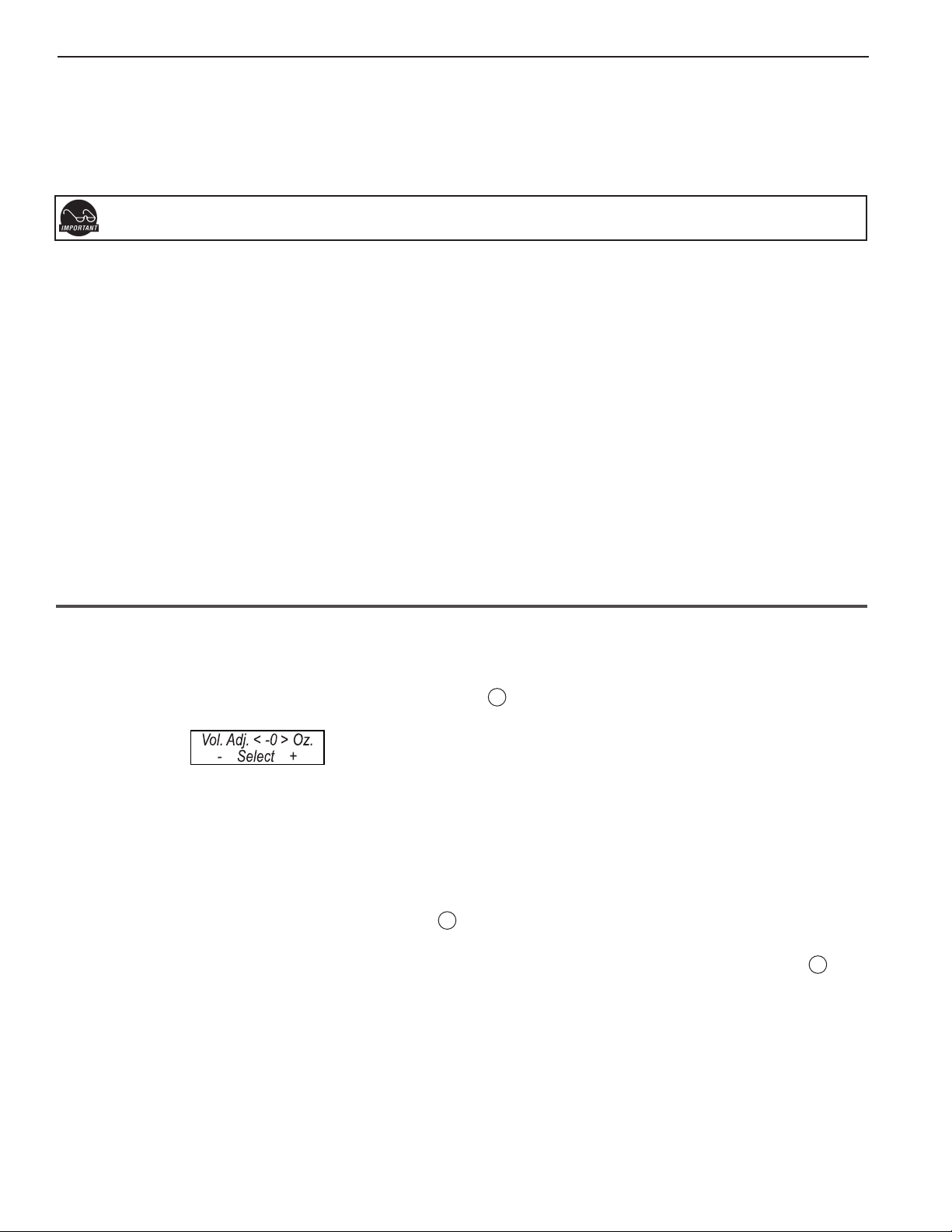
Brew Volume – Easy Access
Units can be easily adjusted from the front panel. Written into the software on the Alpha GT UCM, is a feature to access the brew volume without entering the program mode.
On any multi-station Alpha (ALP2/3/4/5/6GT): Press the center Select button 2 (see illustration, page 2) twice, with the second press hold
down the button for around ve [5] seconds.
The screen will display pressing < or > will adjust the brew volume up or down, ± 20 oz, in 1 ounce increments.
Warmer Temperature Control (Factory set to 90%)
Turn on brewer at the control panel ON/OFF button. Warmer button should be OFF (LED off). Press and hold desired WARMER button. Screen
will display current setting in % of power. Press < or > to increase or decrease power to warmer (50% to 100% in 10% increments). Press to
set.
Tank Temperature Check
Turn on brewer at the control panel ON/OFF button. Press and hold 3 button (see illustration, page 2) for 5 seconds. Water Temperature will
be displayed. The temperature will not display while the unit is in the process of reheating.
NOTE: Alpha 3GT ONLY; when checking tank temperature, rst make sure REAR warmer is ON (red LED on) and then press button 3 for 5
seconds to display tank temperature.
4
Page 5

FRESH-TRAC TIMER
Fresh-Trac Receiver
These instructions will explain the operation and maintenance of the Fresh-Trac coffee timer. This timer will allow the
user to track the freshness of coffee brewed into glass decanters. Fresh-Trac is only available with Curtis Alpha GT
brewers. A ashing light inside the decanter handle signals when the coffee is no longer fresh.
All changes to the timer settings are made at the Alpha’s UCM (Universal Control Module). See Resetting the Timer, on page two. Earlier Alpha
UCM controllers do not have the Fresh-Trac feature.
The Fresh-Trac timer uses a visual alarm in the form of a ashing light.
When a new brewcycle begins, you will observe ve quick ashes indicat-
ing that the timer has started. Timing data is transmitted to the Fresh-Trac
receiver on the decanter. The timer adjustment range is from 10 minutes to
120 minutes. The factory setting is 30 minutes (default time in the UCM).
When time has expired, the Fresh-Trac will light every ve seconds. The
light will turn off completely after one hour or unless you brew again into
the same decanter.
The Fresh-Trac decanter is dish-washer safe. The expected battery life in the light unit is two years. The battery is not
replaceable.
OPERATION OF THE
FRESH-TRAC SYSTEM
TRANSMITTER RANGE
The most effective signal range
of the Fresh-Trac transmitter
is 230º. This is shown as a top
view in the illustration.
5
Page 6

ILLUSTRATED PARTS
ALPHA GT
Alpha 3GT Model Shown,
Other Models Identical
Except Where Noted.
6
Page 7

PARTS LIST
ALPHA GT
ITEM № PART № DESCRIPTION
1 WC-6812 WARMER, ASSY TOP ALP3GT
1A WC-8619 WARMER, TOP ASSY ALP6GT
2 WC-13164 HARNESS ASSY, WARMER ALPGT UPPER WARMER
3 WC-889-101 VALVE, DUMP LEFT 120V 12W
3A WC-860 VALVE, DUMP LEFT 220V 12W
4 WC-2962-101K KIT, SPRAYHEAD
5. WC-37441* KIT UCM & LABEL ALP3GT FRESH-TRAC
6 WC-1809* FAUCET, PS/HSP SERIES HOT WATER 1/2-20 UNF
7 WC-3316* BREW CONE ASSY, w/HANDLE 7.1” DIA.
8 WC-5853-102 COVER, TOP HEATING TANK
9 WC-43062* GASKET, TANK LID
10 WC-4320 O’ RING ½” I.D.
11 WC-5527K* KIT, WATER LEVEL PROBE W/O-RING & NUT
12 WC-4394 GUARD, SHOCK HEATING ELEMENT
13 WC-43055 GUARD, SHOCK RESET THERMOSTAT
14 WC-1438-101* SENSOR, TEMPERATURE TANK
15 WC-522 * THERMOSTAT, HI LIMIT HEATER DPST 277V-40A
16 WC-6267* TANK, COMPLETE ALP-DS/GT 220V
17 WC-2401 ELBOW, 3/8 NPT x 1/4 FLARE PLTD
18 WC-826L* VALVE, INLET 1.15GPM 120Vac 10W
18A WC-856 VALVE, INLET 1 GPM 240V 10W
19 WC-8556* HEATSINK and TRIAC ASSY 40A 600V
20 WC-103 * SWITCH, TOGGLE DPST 25A 125/250VAC RESISTIVE
21 WC-13315-101 HARNESS COMPLETE ALPHAGTN-15
22 WC-5970 COVER, BACK ALP3GT
22A WC-61595-101 COVER, BACK BOTTOM ALP6GT
23 WC-10002D TRANSMITTER ASSY, D-STYLE
24 WC-29025 SPRAYHEAD, ASSY AFS-PURPLE
25 WC-972 * PLATE, WARMER COMPLETE 100W, 120V
25A WC-975 WARMER, ASSY COMPLETE 100W 220V
26 WC-58056 COVER, BOTTOM ALP3GT
26A WC-61596 COVER, BOTTOM ALP6GT
27 WC-3518 LEG, 3/8”-16 X 1/2” L GLIDE
28 70580000303* DECANTER, GLASS CURTIS FRESH-TRAC
29 WC-3503 LEG, 3/8”- 16 STUD SCREW BUMPER
30 CR-10 * FILTER, PAPER COFFEE #506 1000/PKG
31 WC-5310* TUBE, 5/16 ID X 1/8 W SILICONE
32 WC-922-04* KIT,ELEMENT HEATING 3.5KW 220V W/JAM NUTS & SILICONE WASHERS
* SUGGESTED PARTS TO STOCK
7
Page 8

ELECTRICAL SCHEMATIC
8
Page 9

ELECTRICAL SCHEMATIC
9
Page 10

Cleaning the Coffee Brewer
Regular cleaning and preventive maintenance is essential in keeping your coffee brewer looking and working like new.
CAUTION – Do not use cleansers, bleach liquids, powders or any other substance containing chlorine. These
products promote corrosion and will pit the stainless steel. USE OF THESE PRODUCTS WILL VOID THE
WARRANTY.
1. Wipe exterior surfaces with a moist cloth, removing spills and debris.
2. Slide the brew cone out and clean it. Clean the spray head area with a moist clean cloth.
3. Rinse and dry the brew cone.
4. Drain drip tray of coffee. Wash out the drip tray. Dry the tray.
5. Rub a stainless steel polish on the outside surfaces to protect the brewer.
Cleaning Glass Decanter
Curtis glass decanters are dish-washer safe. Coffee decanters may be hand washed.
1. Prepare a mild solution of detergent and warm water.
2. Immerse the decanter in detergent solution and clean with a sponge brush.
3. Thoroughly rinse out the glass decanter with clean warm water.
4. Dry the decanter.
WARNING – To Avoid Damage or Injury
l Do not boil dry or heat pot when empty.
l Do not clean with materials that scratch.
l Do not use gas ame or range top of any kind.
l Do not pour towards people.
l Do not carry two decanters in one hand.
l Clean only with mild detergent or an urn cleaning solution specically intended for coffee decanters.
Liquid Level Probe
Cleaning intervals for the probe are to be determined by the user or the service
tech, based on water conditions. The use of water lters, or the type of water lter
that is being used can impact the service interval. Intervals can be from one month
to several years, however, replacing rather than cleaning the probe is preferable.
WARNING: Disconnect electrical power before removing access panels!
This procedure involves working with hot water and hot surfaces!
1. Unplug the power cord and shut off the water line.
2. Remove the top cover of the unit. Locate the top of the tank and remove the
cover.
3. Drain the tank to a level about 3” below the tip of the probe.
4. Allow some time for the probe to cool before working on the brewer.
5. Clean the tip of the probe using a Scotch-Brite™ scuff pad.
6. If scale is still visible, remove the probe and soak it in vinegar or a scale removing chemical.
7. When assembling the probe back onto the tank, make sure the tip of the probe
is pointing downward as illustrated.
LIQUID LEVEL PROBEHEATING TANK
10
Page 11

ROUGH-IN DRAWING
11
Page 12

Product Warranty Information
The Wilbur Curtis Company certies that its products are free from defects in material and workmanship under normal
use. The following limited warranties and conditions apply:
3 Years, Parts and Labor, from Original Date of Purchase on digital control boards.
2 Years, Parts, from Original Date of Purchase on all other electrical components, ttings and tubing.
1 Year, Labor, from Original Date of Purchase on all electrical components, ttings and tubing.
Additionally, the Wilbur Curtis Company warrants its Grinding Burrs for Forty (40) months from date of purchase or 40,000 pounds
of coffee, whichever comes rst. Stainless Steel components are warranted for two (2) years from date of purchase against leaking
or pitting and replacement parts are warranted for ninety (90) days from date of purchase or for the remainder of the limited warranty
period of the equipment in which the component is installed.
All in-warranty service calls must have prior authorization. For Authorization, call the Technical Support Department at 1-800-995-
0417. Effective date of this policy is April 1, 2003.
Additional conditions may apply. Go to www.wilburcurtis.com to view the full product warranty information.
CONDITIONS & EXCEPTIONS
The warranty covers original equipment at time of purchase only. The Wilbur Curtis Company, Inc., assumes no responsibility for
substitute replacement parts installed on Curtis equipment that have not been purchased from the
Wilbur Curtis Company, Inc. The Wilbur Curtis Company will not accept any responsibility if the following conditions are not met. The
warranty does not cover and is void under the following circumstances:
1) Improper operation of equipment: The equipment must be used for its designed and intended purpose and function.
2) Improper installation of equipment: This equipment must be installed by a professional technician and must comply with all
local electrical, mechanical and plumbing codes.
3) Improper voltage: Equipment must be installed at the voltage stated on the serial plate supplied with this equipment.
4) Improper water supply: This includes, but is not limited to, excessive or low water pressure, and inadequate or uctuating
water ow rate.
5) Adjustments and cleaning: The resetting of safety thermostats and circuit breakers, programming and temperature
adjustments are the responsibility of the equipment owner. The owner is responsible for proper cleaning and regular
maintenance of this equipment.
6) Damaged in transit: Equipment damaged in transit is the responsibility of the freight company and a claim should be
made with the carrier.
7) Abuse or neglect (including failure to periodically clean or remove lime accumulations): Manufacturer is not responsible for
variation in equipment operation due to excessive lime or local water conditions. The equipment must be maintained accord ing to the manufacturer’s recommendations.
8) Replacement of items subject to normal use and wear: This shall include, but is not limited to, light bulbs, shear disks, “0”
rings, gaskets, silicone tube, canister assemblies, whipper chambers and plates, mixing bowls, agitation assemblies and
whipper propellers.
9) Repairs and/or Replacements are subject to our decision that the workmanship or parts were faulty and the defects showed
up under normal use. All labor shall be performed during regular working hours. Overtime charges are the responsibility of
the owner. Charges incurred by delays, waiting time, or operating restrictions that hinder the service technician’s ability to
perform service is the responsibility of the owner of the equipment. This includes institutional and correctional facilities.
The Wilbur Curtis Company will allow up to 100 miles, round trip, per in-warranty service call.
RETURN MERCHANDISE AUTHORIZATION: All claims under this warranty must be submitted to the Wilbur Curtis Company
Technical Support Department prior to performing any repair work or return of this equipment to the factory. All returned equipment must be repackaged properly in the original carton. No units will be accepted if they are damaged in transit due to improper
packaging. NO UNITS OR PARTS WILL BE ACCEPTED WITHOUT A RETURN MERCHANDISE AUTHORIZATION (RMA). RMA
NUMBER MUST BE MARKED ON THE CARTON OR SHIPPING LABEL. All in-warranty service calls must be performed by an
authorized service agent. Call the Wilbur Curtis Technical Support Department to nd an agent near you.
ECN 16020 . 7/17/14@10.7 . rev F
ECN 15888 . 5/22/14@15.2 . rev E
ECN 14661 . 12/28/12@15.2 . revD
ECN 14320 . 8/8/12@14.9
ECN 14032 . 4/24/12@9.0
ECN 13531 . 10/12/11@14.0
EDR 7738. 4/26/11@15.6
12
WILBUR CURTIS CO., INC.
6913AccoSt.,Montebello,CA90640-5403USA
Phone:800/421-6150 Fax:323-837-2410
TechnicalSupportPhone:800/995-0417(M-F5:30A-4:00PPST) E-Mail:techsupport@wilburcurtis.com
Web Site: www.wilburcurtis.com
FOR THE LATEST SPECIFICATION INFORMATION GO TO WWW.WILBURCURTIS.COM
Printed in U.S.A. 7/2014 F-3817 rev F
 Loading...