

Page 1
®
Flush pressure transmitter
For viscous and solids-containing media
Model S-11
Applications
■
Machine building
■
Hydraulic aggregates
■
General industrial applications
■
Food and beverage industry
Special features
Electronic
pressure measurement
WIKA data sheet PE 81.02
■
High-quality product
■
Many congurations possible
■
Flush process connection
■
Large stocks for short delivery times
■
Vacuum-tight
Description
Specialist for viscous and solids-containing media
The model S-11 pressure transmitter with ush diaphragm
has been specically designed for the measurement of
viscous, paste-like, adhesive, crystallising, particle-laden and
contaminated media, which would clog the pressure channel
of conventional process connections.
Through its optimised design, the ush process connection
enables the cleanability of the wetted diaphragm to be
integrated into the process. Low-maintenance and troublefree pressure measurement is thus also guaranteed in critical
applications with frequently changing media.
High accuracy, a robust design, high-quality workmanship
and the high exibility of conguration are key features of the
model S-11.
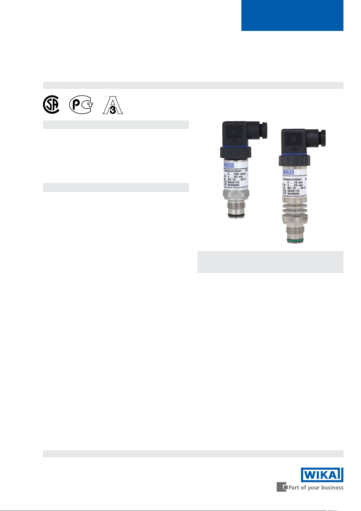
Fig. left: Pressure transmitter model S-11
Fig. right: Pressure transmitter model S-11 with
cooling element
Flush process connection
All process connections of the ush pressure transmitter are
made of stainless steel, all welded and isolate the process
medium from the pressure measuring instrument via a
positive seal. A reliable, dead-space free sealing between
the process connection and the measuring medium is thus
assured.
For high medium temperatures of up to 302 °F (150 °C),
the pressure transmitter is also available with an integrated
cooling element.
Specically for the food and beverage industry, a version
with internal system ll uid in accordance with FDA 21 CFR
178.3750 can be chosen.
Page 1 of 8WIKA data sheet PE 81.02 ∙ 02/2016
Data sheets showing similar products:
Pressure transmitter for general applications; model S-10; see data sheet PE 81.01
Intrinsically safe pressure transmitter; model IS-2X; see data sheet PE 81.50
Pressure transmitter for low pressure applications; model SL-1; see data sheet PE 81.36
Pressure transmitter for highest pressure applications; model HP-1; see data sheet PE 81.29
Page 2

Measuring ranges
Gauge pressure
bar Measuring range 0 ... 0.1 0 ... 0.16 0 ... 0.25 0 ... 0.4 0 ... 0.6 0 ... 1 0 ... 1.6
Overpressure limit 1 1.5 2 2 4 5 10
Measuring range 0 ... 2.5 0 ... 4 0 ... 6 0 ... 10 0 ... 16 0 ... 25 0 ... 40
Overpressure limit 10 17 35 35 80 50 80
Measuring range 0 ... 60 0 ... 100 0 ... 160 0 ... 250 0 ... 400 0 ... 600
Overpressure limit 120 200 320 500 800 1,200
psi Measuring range 0 ... 15 0 ... 20 0 ... 30 0 ... 50 0 ... 60 0 ... 100 0 ... 150
Overpressure limit 145 145 145 240 240 500 500
Measuring range 0 ... 160 0 ... 200 0 ... 250 0 ... 300 0 ... 400 0 ... 500 0 ... 600
Overpressure limit 1,160 1,160 1,160 1,160 1,160 1,160 1,160
Measuring range 0 ... 750 0 ... 1,000 0 ... 1,500 0 ... 2,000 0 ... 3,000 0 ... 5,000 0 ... 6,000
Overpressure limit 1,740 1,740 2,900 4,600 7,200 11,600 11,600
Absolute pressure
bar Measuring range 0 ... 0.25 0 ... 0.4 0 ... 0.6 0 ... 1 0 ... 1.6 0 ... 2.5 0 ... 4
Overpressure limit 2 2 4 5 10 10 17
Measuring range 0 ... 6 0 ... 10 0 ... 16
Overpressure limit 35 35 80
psi Measuring range 0 ... 15 0 ... 25 0 ... 50 0 ... 100 0 ... 250
Overpressure limit 72.5 145 240 500 1,160
Vacuum and +/- measuring range
bar Measuring range -0.6 ... 0 -0.4 ... 0 -0.25 ... 0 -0.16 ... 0 -0.1 ... 0
Overpressure limit 4 2 2 1.5 1
Measuring range -1 ... 0 -1 ... +0.6 -1 ... +1.5 -1 ... +3 -1 ... +5
Overpressure limit 5 10 10 17 35
Measuring range -1 ... +9 -1 ... +15 -1 ... +24
Overpressure limit 35 80 50
psi Measuring range -30 inHg ... 0 -30 inHg ... +30 -30 inHg ... +60 -30 inHg ... +100 -30 inHg ... +160
Overpressure limit 72.5 240 240 500 1,160
Measuring range -30 inHg ... +200 -30 inHg ... +300
Overpressure limit 1,160 1,160
The given measuring ranges are also available in mbar, MPa and further units.
Vacuum tightness
Ye s
Page 2 of 8 WIKA data sheet PE 81.02 ∙ 02/2016
Page 3

Output signals
Accuracy data
Signal type Signal
Current (2-wire) 4 ... 20 mA
Current (3-wire) 0 ... 20 mA
Voltage (3-wire) DC 0 ... 10 V
DC 0 ... 5 V
Other output signals on request.
Depending on the signal type the following loads apply:
Current (2-wire) ≤ (power supply - 10 V) / 0.02 A
Current (3-wire) ≤ (power supply - 3 V) / 0.02 A
Voltage (3-wire) > max. output signal / 1 mA
Voltage supply
Power supply
The power supply depends on the selected output signal
4 ... 20 mA (2-wire) DC 10 ...30 V
0 ... 20 mA (3-wire) DC 10 ...30 V
DC 0 ... 10 V DC 14 ... 30 V
DC 0 ... 5 V DC 10 ...30 V
Accuracy at reference conditions
Standard ≤ ±0.5 % of span
Option ≤ ±0.25 % of span
1) Only for measuring ranges ≥ 0.25 bar
Including non-linearity, hysteresis, zero oset and end value
deviation (corresponds to measured error per IEC 61298-2).
Calibrated in vertical mounting position with process connection facing downwards.
Non-linearity (per IEC 61298-2)
≤ ±0.2 % of span BFSL
Non-repeatability
≤ ±0.1 % of span
Temperature error in rated temperature range
Rated temperature range:
32 ... 176 °F (0 ... 80 °C)
Mean temperature coecient of zero point:
Measuring range > 0.25 bar ≤ 0.2 % of span/10 K
Measuring range ≤ 0.25 bar < 0.4 % of span/10 K
Mean temperature coecient of span:
≤ 0.2 % of span/10 K
1)
Reference conditions (per IEC 61298-1)
Temperature
59 ... 77 °F (15 ... 25 °C)
Atmospheric pressure
12.47 ... 15.37 psi (860 ... 1,060 mbar)
Humidity
45 ... 75 % r. h.
Power supply
DC 24 V
Mounting position
Calibrated in vertical mounting position with process
connection facing downwards.
Long-term drift
≤ ±0.2 % of span/year
Adjustability of zero point and span
Adjustment is made using potentiometers inside the
instrument.
Not possible for cable outlet with ingress protection IP 68.
Zero point ± 5 %
Span ± 5 %
Time response
Settling time
≤ 10 ms
Page 3 of 8WIKA data sheet PE 81.02 ∙ 02/2016
Page 4

Operating conditions
Electrical connections
Ingress protection (per IEC 60529)
The ingress protection depends on the type of electrical
connection.
Electrical connection Ingress protection
Angular connector DIN 175301-803 A IP 65
Circular connector M12 x 1 (4-pin) IP 67
Cable outlet
■
Standard IP 67
■
Option IP 68
2) Adjustability of zero point and span not possible.
2)
The stated ingress protection only applies when plugged in
using mating connectors that have the appropriate ingress
protection.
Vibration resistance
Process connections without cooling element:
20 g (IEC 60068-2-6, under resonance)
Process connections with cooling element:
10 g (IEC 60068-2-6, under resonance)
Shock resistance
Process connections without cooling element:
1,000 g (IEC 60068-2-27, mechanical)
Process connections with cooling element:
400 g
(IEC 60068-2-27, mechanical)
Permissible temperature ranges
Also meets EN 50178, tab. 7, operation (C) 4K4H,
storage (D) 1K4, transport (E) 2K3.
Process connections without cooling element
Medium
■
Standard -30 ... +100 °C -22 ... +212 °F
■
Option -30 ... +125 °C -22 ... +257 °F
Ambient -20 ... +80 °C -4 ... +176 °F
Storage -40 ... +100 °C -40 ... +212 °F
Process connections with cooling element
Medium -20 ... +150 °C -4 ... +302 °F
Ambient -20 ... +80 °C -4 ... +176 °F
Storage -40 ... +100 °C -40 ... +212 °F
Short-circuit resistance
S
vs. U
-
+
Reverse polarity protection
U+ vs. U
-
Overvoltage protection
DC 36 V
Insulation voltage
DC 500 V with NEC class 02 voltage supply (low voltage and
low current max. 100 VA even under fault conditions)
Connection diagrams
Angular connector DIN 175301-803 A
2-wire 3-wire
U
1 1
1
3
2
Wire cross-section max. 1.5 mm
Cable diameter 6 ... 8 mm (0.24 ... 0.31")
+
U
2 2
-
- 3
S
+
2
(AWG 16)
Circular connector M12 x 1 (4-pin)
2-wire 3-wire
U
1 1
3
4
2
1
+
U
3 3
-
- 4
S
+
Cable outlet
2-wire 3-wire
U
+
U
-
S
+
Shield grey grey
Wire cross-section 6 x 0.5 mm² (AWG 20)
Cable diameter 6.8 mm (0.27")
Cable lengths 1.5 m, 3 m, 5 m, 10 m, 15 m
(4.9 ft, 9.8 ft, 16.4 ft, 32.8 ft, 49.2 ft)
brown brown
green green
- white
Other connections on request.
Page 4 of 8 WIKA data sheet PE 81.02 ∙ 02/2016
Page 5

Process connections
Process connection Available measuring ranges
G ½ B ush
G 1 B ush
Hygienic G 1 B ush
(in accordance with 3-A Sanitary
Standards)
3) Process connection also available with cooling element.
Cooling elements
For higher medium temperatures process connections with cooling element are available (see
“Operating conditions”) .
Sealing
Process
connection
without cooling
element
with cooling
element
Hygienic up to 302 °F (150 °C) EPDM
4) Minimum permissible medium and ambient temperature -20 °C / -4 °F
3)
3)
Max. medium
temperature
up to 212 °F (100 °C) NBR
up to 257 °F (125 °C) NBR
up to 302 °F (150 °C) FKM/FPM
0 ... 2.5 to 0 ... 600 bar 0... 50 to 0 ... 6,000 psi
0 ... 0.1 to 0 ... 1.6 bar 0 ... 15 psi
0 ... 0.1 to 0 ... 25 bar 0 ... 15 to 0 ... 300 psi, respectively
Sealing material and max. pressure limitation
Standard Option 1 Option 2
4)
4)
up to 8,700 psi (600 bar)
up to 8,700 psi (600 bar)
4)
up to 4,350 psi (300 bar)
up to 2,900 psi (200 bar)
FKM/FPM
up to 8,700 psi (600 bar)
FKM/FPM
up to 5,800 psi (400 bar)
EPDM
up to 2,900 psi (200 bar)
- -
EPDM
up to 2,900 psi (200 bar)
EPDM
up to 2,900 psi (200 bar)
-
The sealings listed under “Standard” are included in the delivery.
Materials
Wetted parts
■
Stainless steel
■
For sealing materials see “Process connections”
Non-wetted parts
Internal system ll uid
Standard Synthetic oil
Option Food-compatible system ll uid per FDA 21 CFR
178.3750
Page 5 of 8WIKA data sheet PE 81.02 ∙ 02/2016
Page 6

CE conformity
Pressure equipment directive
97/23/EC
EMC directive
2004/108/EC, EN 61326 emission (group 1, class B) and
interference immunity (industrial application)
Approvals
■
CSA, safety (e.g. electr. safety, overpressure, ...), Canada
■
GOST-R, import certicate, Russia
■
GOST, metrology/measurement technology, Russia
■
3-A 5), food, USA
■
CRN, safety (e.g. electr. safety, overpressure, ...), Canada
5) 3-A only for instruments with hygienic process connection G 1 B
Approvals, see website
Page 6 of 8 WIKA data sheet PE 81.02 ∙ 02/2016
Page 7

Dimensions in mm (inch)
Pressure transmitter
with angular connector DIN 175301-803
A
Weight approx. 0.2 kg / 7 oz
Process connections
with M12 x 1 circular connector with cable outlet
Weight approx. 0.2 kg / 7 oz Weight approx. 0.2 kg / 7 oz
G D1 L1 L2 L3 L4
G ½ B 18
(0.71)23(0.91)
20.5
(0.81)10(0.4)
15.5
(0.61)
G D1 L1 L2 L3 L4
G 1 B 30
(1.19)23(0.91)
20.5
(0.81)10(0.4)
15.5
(0.61)
G D1 L1 L2 L3 L4
G 1 B
hygienic
29.5
(1.17)28(1.11)25(0.99)9(0.36)
For information on tapped holes and welding sockets, see Technical information IN 00.14 at www.wika.com.
15.5
(0.61)
Page 7 of 8WIKA data sheet PE 81.02 ∙ 02/2016
Page 8

Accessories
Welding socket
Designation Order no.
Welding socket for G ½ B ush 1192299
Welding socket for G 1 B ush 1192264
Welding socket for G 1 B hygienic flush 14070973
Welding socket for G 1 B hygienic flush with leak-control channel 14070974
Further adapter systems for for measuring instruments with process connection G 1 B hygienic, see data sheet AC 09.20.
Mating connector
Designation Order no.
without cable 2 m cable, shielded 5 m cable, shielded 10 m cable, shielded
Angular connector DIN 175301-803 A
■
with cable gland, metric 11427567 14100465 14100466 -
■
with cable gland, conduit 11022485 - - -
Circular connector M12 x 1 (4-pin)
■
straight - 14086880 14086883 14086884
■
angled - 14086889 14086891 14086892
Sealings for mating connectors
Mating connector Order no.
Blue (WIKA) Brown (neutral)
Angular connector DIN EN 175301-803 A 1576240 11437902
Sealings for process connection
Thread size and sealing Order no.
NBR FPM/FKM EPDM
G ½ B
■
O-ring 14072275 14072276 14072277
■
Prole sealing 1039067 1039075 1538306
G 1 B
■
O-ring 1108247 1099094 1535056
■
Prole sealing 1100386 1145967 11522381
G 1 B hygienic
■
O-ring - - 2225859
■
Prole sealing - - 11522381
Ordering information
Model / Measuring range / Output signal / Accuracy / Electrical connection / Medium temperature / Process connection /
Sealing / System ll uid
© 2012 WIKA Alexander Wiegand SE & Co. KG, all rights reserved.
The specications given in this document represent the state of engineering at the time of publishing.
We reserve the right to make modications to the specications and materials.
Page 8 of 8 WIKA data sheet PE 81.02 ∙ 02/2016
WIKA Instrument Corporation
1000 Wiegand Boulevard
Lawrenceville, GA 30043-5868
Tel: 888-WIKA-USA • 770-513-8200
Fax: 770-338-5118
E-Mail: info@wika.com
www.wika.com
MM/YYYY country code based on 07/2014 GB
 Loading...