

Page 1
Operating instructions
Betriebsanleitung
Mode d'emploi
Manual de instrucciones
Flush diaphragm pressure transmitter model S-11
Druckmessumformer mit frontbündiger Membrane Typ S-11
Transmetteur de pression à membrane aeurante type S-11
Transmisor de presión con membrana aorante modelo
Flush diaphragm pressure transmitter model S-11
S-11
GB
D
F
E
Page 2

GB
Operating instructions model S-11 Page 3 - 26
D
Betriebsanleitung Typ S-11 Seite 27 - 50
F
Mode d'emploi type S-11 Page 51 - 76
E
Manual de instrucciones modelo S-11 Página 77 - 99
© 2012 WIKA Alexander Wiegand SE & Co. KG
All rights reserved. / Alle Rechte vorbehalten.
WIKA® is a registered trademark in various countries.
WIKA® ist eine geschützte Marke in verschiedenen Ländern.
Prior to starting any work, read the operating instructions!
Keep for later use!
Vor Beginn aller Arbeiten Betriebsanleitung lesen!
Zum späteren Gebrauch aufbewahren!
Lire le mode d‘emploi avant de commencer toute opération !
A conserver pour une utilisation ultérieure !
¡Leer el manual de instrucciones antes de comenzar cualquier trabajo!
¡Guardar el manual para una eventual consulta posterior!
2 WIKA operating instructions
14043046.01 06/2012 GB/D/F/E
Page 3
Contents
Contents
1. General information 4
2. Safety 6
3. Specications 9
4. Design and function 15
5. Transport, packaging and storage 15
6. Commissioning, operation 16
7. Adjustment of zero point and span 21
8. Maintenance and cleaning 22
9. Faults 23
10. Dismounting, return and disposal 24
11. Accessories 25
GB
12. Appendix 1: EC Declaration of conformity model S-11 26
Declarations of conformity can be found online at www.wika.com.
14043046.01 06/2012 GB/D/F/E
3WIKA operating instructions pressure transmitter, model S-11
Page 4

1. General information
1. General information
■
The pressure transmitter described in the operating instructions has been designed and manufac-
GB
tured using state-of-the-art technology. All components are subject to stringent quality and
environmental criteria during production. Our management systems are certied to ISO 9001 and
ISO 14001.
■
These operating instructions contain important information on handling the instrument. Working
safely requires that all safety instructions and work instructions are observed.
■
Observe the relevant local accident prevention regulations and general safety regulations for the
instrument's range of use.
■
The operating instructions are part of the product and must be kept in the immediate vicinity of the
instrument and readily accessible to skilled personnel at any time.
■
Skilled personnel must have carefully read and understood the operating instructions, prior to beginning any work.
■
The manufacturer's liability is void in the case of any damage caused by using the product contrary
to its intended use, non-compliance with these operating instructions, assignment of insuciently
qualied skilled personnel or unauthorised modications to the instrument.
■
The general terms and conditions contained in the sales documentation shall apply.
■
Subject to technical modications.
■
Further information:
- Internet address: www.wika.de / www.wika.com
- Relevant data sheet: PE 81.02
- Application consultant:
Tel.: (+49) 9372/132-8976
Fax: (+49) 9372/132-8008976
E-mail: support-tronic@wika.de
4 WIKA operating instructions pressure transmitter, model S-11
14043046.01 06/2012 GB/D/F/E
Page 5
1. General information
Explanation of symbols
WARNING!
... indicates a potentially dangerous situation that can result in serious injury or death, if not
avoided.
CAUTION!
... indicates a potentially dangerous situation that can result in light injuries or damage to
equipment or the environment, if not avoided.
Information
… points out useful tips, recommendations and information for ecient and trouble-free
operation.
CAUTION!
... indicates a potentially dangerous situation that can result in burns, caused by hot
surfaces or liquids, if not avoided.
Abbreviations
2-wire The two connection lines are used for the voltage supply.
The measurement signal also provides the supply current.
3-wire Two connection lines are used for the power supply.
One connection line is used for the measurement signal.
U
+
U
-
S
+
Positive power supply terminal
Reference potential
Analogue output
GB
14043046.01 06/2012 GB/D/F/E
5WIKA operating instructions pressure transmitter, model S-11
Page 6
2. Safety
2. Safety
WARNING!
GB
2.1 Intended use
The pressure transmitter is used to convert pressure into an electrical signal indoors and outdoors.
The instrument has been designed and built solely for the intended use described here, and may only
be used accordingly.
The technical specications contained in these operating instructions must be observed. Improper
handling or operation of the pressure transmitter outside of its technical specications requires the
instrument to be taken out of service immediately and inspected by an authorised WIKA service
engineer.
Before installation, commissioning and operation, ensure that the appropriate pressure
transmitter has been selected in terms of measuring range, design and specic measuring
conditions.
Non-observance can result in serious injury and/or damage to equipment.
WARNING!
■
Open the connections only after the system has been depressurised.
■
Observe the working conditions in accordance with chapter 3 "Specications".
■
Always operate the pressure transmitter within the overpressure limit.
Further important safety instructions can be found in the individual chapters of these
operating instructions.
The manufacturer shall not be liable for claims of any type based on operation contrary to the intended
use.
6 WIKA operating instructions pressure transmitter, model S-11
14043046.01 06/2012 GB/D/F/E
Page 7
2. Safety
2.2 Personnel qualication
WARNING!
Risk of injury should qualication be insucient!
Improper handling can result in considerable injury and damage to equipment.
The activities described in these operating instructions may only be carried out by skilled
personnel who have the qualications described below.
Skilled personnel
Skilled personnel are understood to be personnel who, based on their technical training, knowledge
of measurement and control technology and on their experience and knowledge of country-specic
regulations, current standards and directives, are capable of carrying out the work described and
independently recognising potential hazards.
Special operating conditions require further appropriate knowledge, e.g. of aggressive media.
2.3 Special hazards
WARNING!
For hazardous media such as oxygen, acetylene, ammable or toxic gases or liquids,
and refrigeration plants, compressors, etc., in addition to all standard regulations, the
appropriate existing codes or regulations must also be followed.
WARNING!
Residual media in the dismounted pressure transmitter can result in a risk to persons, the
environment and equipment.
Take sucient precautionary measures.
GB
Do not use this instrument in safety or emergency stop devices. Incorrect use of the
instrument can result in injury.
Should a failure occur, aggressive media with extremely high temperature and under high
pressure or vacuum may be present at the instrument.
14043046.01 06/2012 GB/D/F/E
7WIKA operating instructions pressure transmitter, model S-11
Page 8

2. Safety
2.4 Labelling / safety marks
Product label
GB
Measuring range
Output signal
Power supply
S# Serial no.
P# Product no.
If the serial number and the 2D code become illegible due to mechanical damage or overpainting,
traceability will no longer be possible.
Explanation of symbols
CSA, Canadian Standard Association®
The instrument was inspected and certied by CSA International. Instruments bearing this
mark comply with the applicable Canadian and US standards on safety.
GOST, Gossudarstwenny Standart (Государственный Стандарт)
GOST-R (mark)
Instruments bearing this mark comply with the applicable Russian national safety regulations
(Russian Federation).
CE, Communauté Européenne
Instruments bearing this mark comply with the relevant European directives.
Approvals
Pin assignment
2D code
8 WIKA operating instructions pressure transmitter, model S-11
14043046.01 06/2012 GB/D/F/E
Page 9

3. Specications
3. Specications
3.1 Measuring ranges
Relative pressure
bar Measuring range 0 ... 0.1 0 ... 0.16 0 ... 0.25 0 ... 0.4 0 ... 0.6 0 ... 1 0 ... 1.6
Overpressure limit 1 1.5 2 2 4 5 10
Burst pressure 2 2 2.4 2.4 4.8 6 12
Measuring range 0 ... 2.5 0 ... 4 0 ... 6 0 ... 10 0 ... 16 0 ... 25 0 ... 40
Overpressure limit 10 17 35 35 80 50 80
Burst pressure 12 20.5 42 42 96 96 400
Measuring range 0 ... 60 0 ... 100 0 ... 160 0 ... 250 0 ... 400 0 ... 600
Overpressure limit 120 200 320 500 800 1,200
Burst pressure 550 600 600 600 1,600 1,600
Absolute pressure
bar Measuring range 0 ... 0.25 0 ... 0.4 0 ... 0.6 0 ... 1 0 ... 1.6 0 ... 2.5 0 ... 4
Overpressure limit 2 2 4 5 10 10 17
Burst pressure 2.4 2.4 4.8 6 12 12 20.5
Measuring range 0 ... 6 0 ... 10 0 ... 16
Overpressure limit 35 35 80
Burst pressure 42 42 96
Vacuum and +/- measuring range
bar Measuring range -0.1 ... 0 -0.16 ... 0 -0.25 ... 0 -0.4 ... 0 -0.6 ... 0 -1 ... 0 -1 ... +0.6
Overpressure limit 1 1.5 2 2 4 5 10
Burst pressure 2 2 2.4 2.4 4.8 6 12
Measuring range -1 ... +1.5 -1 ... +3 -1 ... +5 -1 ... +9 -1 ... +15 -1 ... +24
Overpressure limit 10 17 35 35 80 50
Burst pressure 12 20.5 42 42 96 96
14043046.01 06/2012 GB/D/F/E
GB
9WIKA operating instructions pressure transmitter, model S-11
Page 10

3. Specications
Vacuum tightness
Yes
GB
3.2 Output signals
Signal type Signal
Current (2-wire) 4 ... 20 mA
Current (3-wire) 0 ... 20 mA
Voltage (3-wire) DC 0 ... 10 V
Depending on the signal type the following loads apply:
Signal type Load in Ω
Current (2-wire) ≤ (power supply - 10 V) / 0.02 A
Current (3-wire) ≤ (power supply - 3 V) / 0.02 A
Voltage (3-wire) > maximum output signal / 1 mA
3.3 Voltage supply
Power supply
The permissible power supply depends on the corresponding output signal.
Output signal Power supply
4 ... 20 mA (2-wire) DC 10 ...30 V
0 ... 20 mA (3-wire) DC 10 ...30 V
DC 0 ... 10 V DC 14 ... 30 V
DC 0 ... 5 V DC 10 ...30 V
DC 0 ... 5 V
10 WIKA operating instructions pressure transmitter, model S-11
14043046.01 06/2012 GB/D/F/E
Page 11

3. Specications
3.4 Accuracy
Accuracy at room temperature
■
Standard: ≤ ±0.5 % of span
■
Option: ≤ ±0.25 % of span
1) Only for measuring ranges ≥ 0.25 bar
Including non-linearity, hysteresis, zero oset and end value deviation (corresponds to measured error
per IEC 61298-2). Calibrated in vertical mounting position with process connection facing downwards.
Non-linearity (per IEC 61298-2)
≤ ±0.2 % of span BFSL
Non-repeatability
≤ ±0.1 % of span
Temperature error in rated temperature range
Nominal temperatur: 0 ... 80 °C
Mean temperature coecient of zero point
■
≤ 0.2 % of span/10 K
■
< 0.4 % of span/10 K
1) Applies to measuring ranges ≤ 0,25 bar
1)
Mean temperature coecient of span
■
≤ 0.2 % of span/10 K
1)
GB
Settling time
≤ 10 ms
Long-term drift
≤ ±0.2 % of span/year
14043046.01 06/2012 GB/D/F/E
11WIKA operating instructions pressure transmitter, model S-11
Page 12

3. Specications
Adjustability of zero point and span
1)
Adjustment is made using potentiometers inside the instrument.
Zero point ± 5 %
GB
Span ± 5 %
1) Adjustment not possible for cable outlet with ingress protection IP 68
3.5 Operating conditions
Ingress protection (per IEC 60529)
The ingress protection depends on the type of electrical connection.
Electrical connection Ingress protection
Angular connector DIN 175301-803 A IP 65
Circular connector M12 x 1 (4-pin) IP 67
Cable outlet
■
Standard IP 67
■
Option IP 68
1) Adjustability of zero point and span not possible
1)
The stated ingress protection only applies when plugged in using mating connectors that have the
appropriate ingress protection.
Vibration resistance
■
Process connections without cooling element
20 g (IEC 60068-2-6, under resonance)
■
Process connections with cooling element
10 g (IEC 60068-2-6, under resonance)
12 WIKA operating instructions pressure transmitter, model S-11
14043046.01 06/2012 GB/D/F/E
Page 13

3. Specications
Shock resistance
■
Process connections without cooling element
1,000 g (IEC 60068-2-27, mechanical)
■
Process connections with cooling element
400 g (IEC 60068-2-27, mechanical)
Permissible temperature ranges
Process connections without cooling element
Ambient -20 ... +80 °C
Storage -40 ... +100 °C
1)
Medium
■
Standard -30 ... +100 °C
■
Option -30 ... +125 °C
1) For measuring ranges 0 ... 400 and 0 ... 600 bar, the medium temperature is limited to -30 ... +70 °C.
2) In vertical mounting position the measuring point must be insulated in order to avoid inuences of heat radiation and convection.
3.6 Electrical connections
Short-circuit resistance
S+ vs. U
-
Reverse polarity protection
U+ vs. U
-
Overvoltage protection
DC 36 V
Process connections with cooling element
Ambient -20 ... +80 °C
Storage -40 ... +100 °C
Medium
1)
-20 ... +150 °C
GB
Insulation voltage
DC 500 V with NEC class 02 voltage supply (low voltage and low current max. 100 VA even under fault
conditions).
14043046.01 06/2012 GB/D/F/E
13WIKA operating instructions pressure transmitter, model S-11
Page 14

3. Specications
3.7 Process connections
Process connection Available measuring ranges
GB
G ½ B ush
G 1 B ush
Hygienic G 1 B ush 0 ... 0.1 to 0 ... 25 bar
3.8 Materials
Wetted parts
■
Stainless steel
■
For sealing materials see table
Process connection Standard Option
without cooling element NBR
with cooling element FPM/FKM EPDM
Hygienic EPDM -
Non-wetted parts
Internal system ll uid
■
Standard: Synthetic oil
■
Option: Food-compatible system ll uid per FDA 21 CFR 178.3750
3.9 Approvals, directives and certicates
Approval
■
CSA
■
GOST
1)
1)
0 ... 2.5 to 0 ... 600 bar
0 ... 0.1 to 0 ... 1.6 bar
■
FPM/FKM
■
EPDM
14 WIKA operating instructions pressure transmitter, model S-11
14043046.01 06/2012 GB/D/F/E
Page 15

3. Specications / 4. ... / 5. Transport, packaging and storage
CE conformity
■
EMC directive 2004/108/EC, EN 61326 emission (group 1, class B) and immunity (industrial
application)
■
Pressure equipment directive 97/23/EC
For special model numbers, e.g. S-11000, please note the specications stated on the delivery note.
For further specications see WIKA data sheet PE 81.02 and the order documentation.
4. Design and function
4.1 Description
The prevailing pressure is measured at the sensor element through the deformation of a diaphragm.
By supplying power, this deformation of the diaphragm is converted into an electrical signal. The output
signal from the pressure transmitter is amplied and standardised. The output signal is proportional to
the measured pressure.
4.2 Scope of delivery
Cross-check the scope of delivery with the delivery note.
5. Transport, packaging and storage
5.1 Transport
Check the pressure transmitter for any damage that may have been caused during transportation.
Obvious damage must be reported immediately.
GB
5.2 Packaging
Do not remove packaging until just before mounting.
Keep the packaging as it will provide optimum protection during transport (e.g. change in installation site,
sending for repair).
14043046.01 06/2012 GB/D/F/E
15WIKA operating instructions pressure transmitter, model S-11
Page 16
5. Transport, packaging, ... / 6. Commissioning, operation
5.3 Storage
Permissible conditions at the place of storage:
■
GB
Storage temperature: see chapter 3 “Specications”
■
Humidity: 45 ... 75 % relative humidity
Avoid exposure to the following factors:
■
Mechanical vibration, mechanical shock (putting it down hard)
■
Soot, vapour, dust and corrosive gases
■
Potentially explosive environments, ammable atmospheres
Store the pressure transmitter in its original packaging in a location that fulls the conditions listed
above. If the original packaging is not available, pack and store the instrument as described below:
1. Place the protection cap on the process connection
2. Place the instrument, along with shock-absorbent material, in the packaging.
WARNING!
Before storing the instrument (following operation), remove any residual media. This is of
particular importance if the medium is hazardous to health, e.g. caustic, toxic, carcinogenic,
radioactive, etc..
6. Commissioning, operation
CAUTION!
Prior to commissioning, the pressure transmitter must be subjected to a visual inspection.
■
Leaking uid is indicative of damage.
■
Check the diaphragm of the process connection for any damage.
■
Only use the pressure transmitter if it is in perfect condition with respect to safety.
16 WIKA operating instructions pressure transmitter, model S-11
14043046.01 06/2012 GB/D/F/E
Page 17
6. Commissioning, operation
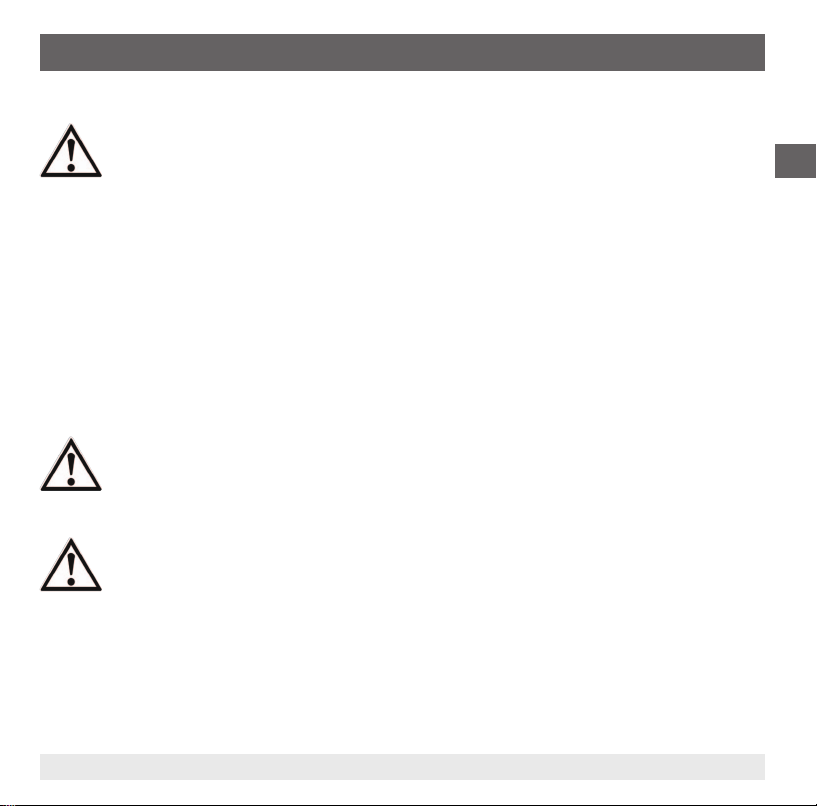
6.1 Mechanical mounting
■
Remove the protection cap not until shortly before installation.
■
Ensure that the diaphragm of the process connection is not damaged
during installation.
■
The sealing faces at the pressure transmitter and the measuring point
always have to be clean.
■
Only ever screw in, or unscrew, the instrument using the spanner
ats. Never use the case or the cooling element as a working surface.
■
The correct torque depends on the dimensions of the process
connection and the gasket used (form/material).
■
When screwing in, do not cross the threads.
■
For information on tapped holes and welding sockets, see Technical
information IN 00.14 at www.wika.com.
■
Attach the connector and screw it in hand-tight. The assembly of the
angular connector is described in chapter 6.2 "Electrical mounting".
Sealing
Correct sealing of the process
connections with parallel threads
at the sealing face
must be
made using suitable at gaskets,
sealing rings or WIKA prole
sealings. The sealing of tapered
threads (e.g. NPT threads) is
made by providing the thread with
additional sealing material such as, for example, PTFE tape (EN 837-2).
Parallel thread Tapered thread
per EN 837 per DIN 3852-E
GB
Spanner ats
NPT, R and PT
For further information on seals see WIKA data sheet AC 09.08 or under www.wika.com.
14043046.01 06/2012 GB/D/F/E
17WIKA operating instructions pressure transmitter, model S-11
Page 18
6. Commissioning, operation
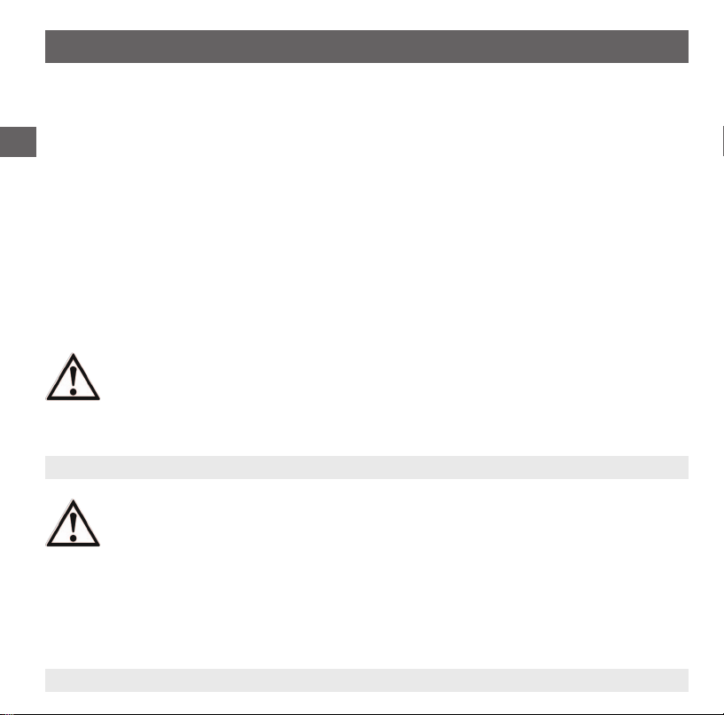
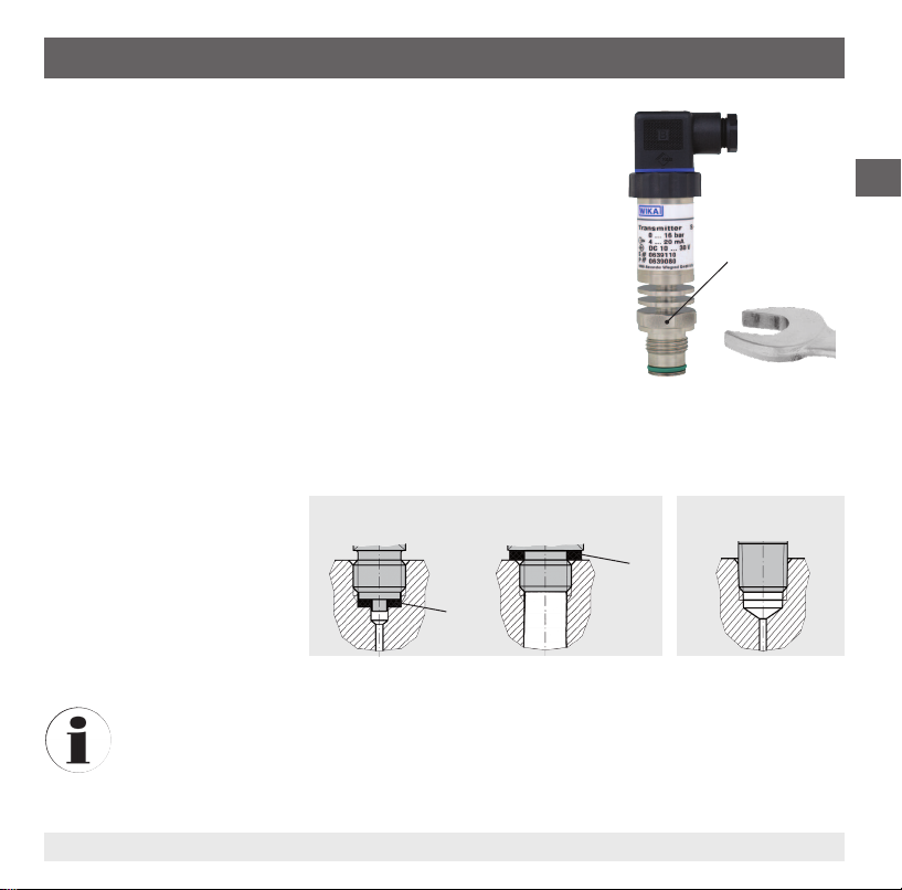
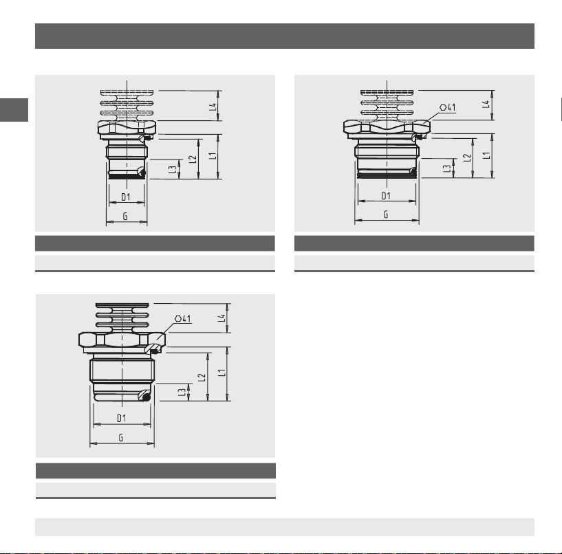
Dimensions of the process connections in mm
GB
G D1 L1 L2 L3 L4
G ½ B 18 23 20.5 10 15.5
G D1 L1 L2 L3 L4
G 1 B hygienic 29.5 28 25 9 15.5
18 WIKA operating instructions pressure transmitter, model S-11
G D1 L1 L2 L3 L4
G 1 B 30 23 20.5 10 15.5
For information on tapped holes and welding
sockets, see Technical information IN 00.14 at
www.wika.com.
14043046.01 06/2012 GB/D/F/E
Page 19
6. Commissioning, operation
6.2 Electrical mounting
■
The instrument must be earthed via the process connection.
■
For instruments with voltage output, use shielded cable, and, if the cables are longer than 30 m or
they leave the building, earth the shield at least at one end of the cable.
■
In North America, use the instrument in line with "class 2 circuits" or "class 2 power units" in accordance with CEC (Canadian Electrical Code) or NEC (National Electrical Code).
■
Select a cable diameter that matches the cable gland of the plug. Make sure that the cable gland of
the mounted plug has a tight t and that the seals are present and undamaged. Tighten the threaded
connection and check that the seal is correctly seated, in order to ensure a tight seal.
■
For cable outlets, make sure that no moisture enters at the cable end.
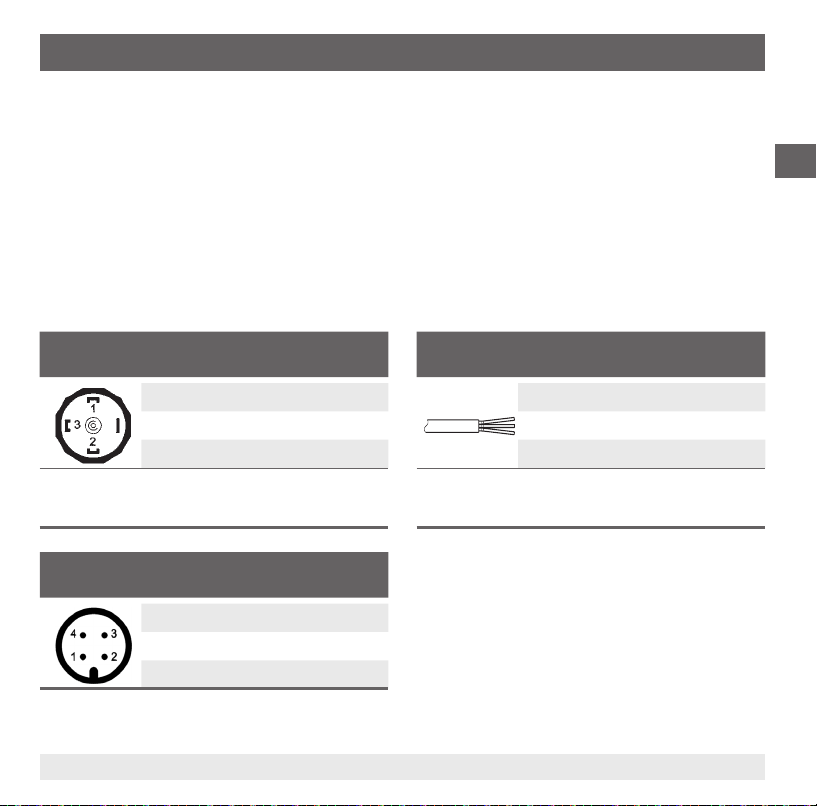
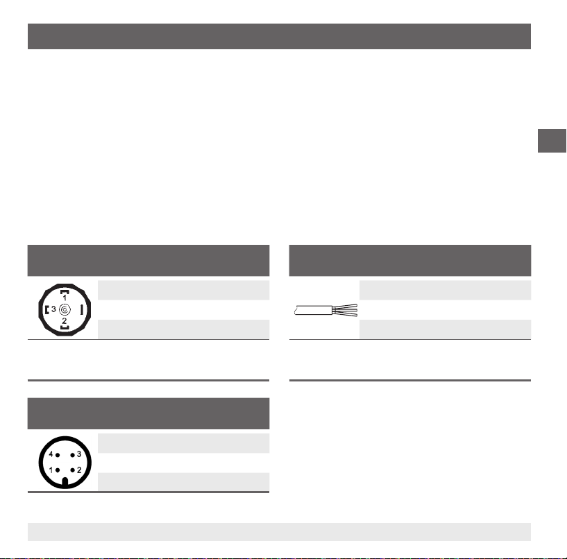
Connection diagrams
Angular connector DIN 175301-803 A
2-wire 3-wire
U+1 1
U-2 2
- 3
S
+
Wire cross-section max. 1.5 mm
Cable diameter 6 ... 8 mm
2
Circular connector M12 x 1 (4-pin)
2-wire 3-wire
U+1 1
3 3
U
-
- 4
S
+
Cable outlet, unshielded
2-wire 3-wire
U+brown brown
U-green green
- white
S
+
Wire cross-section 3 x 0.5 mm
Cable diameter 6.8 mm
Cable lengths 1.5 m, 3 m, 5 m, 10 m, 15 m
2
GB
14043046.01 06/2012 GB/D/F/E
19WIKA operating instructions pressure transmitter, model S-11
Page 20
6. Commissioning, operation
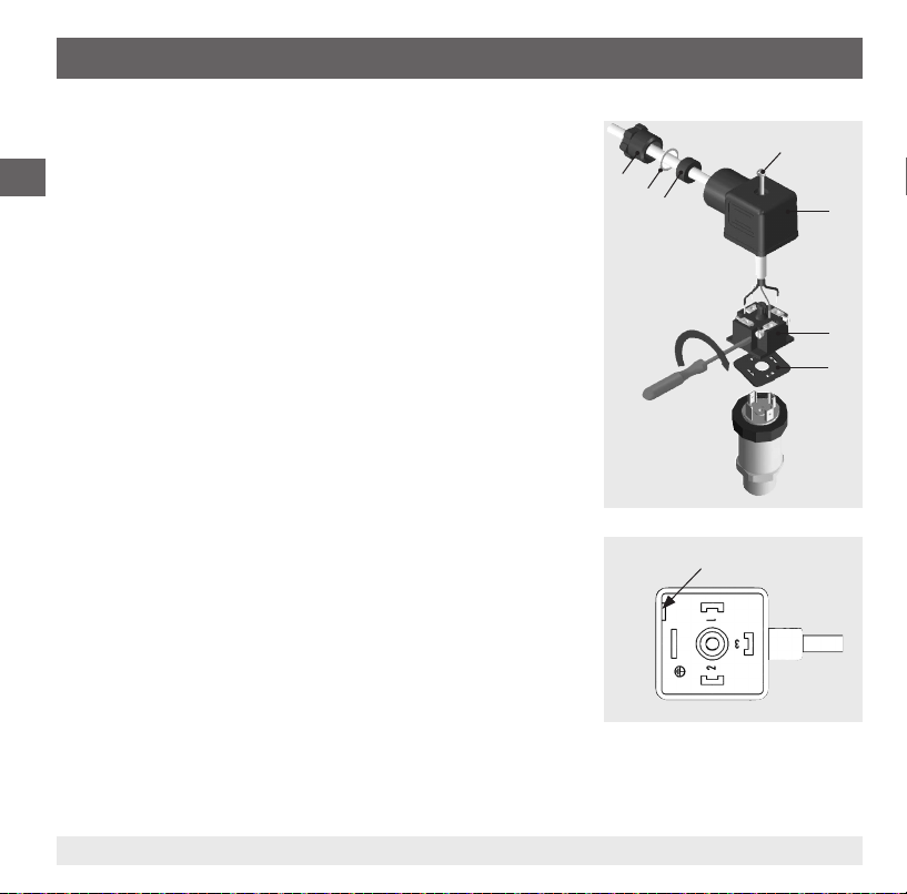
Fitting a DIN 175301-803 angular connector
1. Loosen the screw .
2. Loosen the cable gland .
GB
3. Pull the angled socket + from the instrument.
4. Via the mounting hole , lever the terminal block out of the
case .
5. Pass the cable with the appropriate cable outer diameter (see
"Connection diagrams") through the cable gland , ring ,
sealing and the case .
6. Connect the cable ends to the connection terminals on the
terminal block in accordance with the pin assignment (see
"Connection diagrams" for the pin assignment).
7. Press the terminal block into the case .
8. 8. Tighten the cable gland around the cable. Make sure that
the cable gland and seal are not damaged and that they are
assembled correctly in order to ensure ingress protection.
9. Place the at, square gasket over the pressure transmitter's
connection pins.
10. Slide the assembled angled socket + onto the pressure
transmitter's connection pins.
11. Using the screw , screw the angled socket to the pressure
transmitter, hand-tight.
Mounting hole
20 WIKA operating instructions pressure transmitter, model S-11
14043046.01 06/2012 GB/D/F/E
Page 21
7. Adjustment of zero point and span
7. Adjustment of zero point and span
Only adjust the span-setting potentiometer if calibration equipment is available which has at
least three times the accuracy of the pressure transmitter.
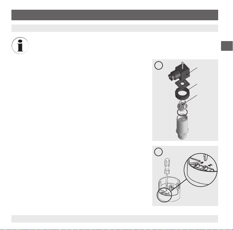
7.1 Preparation (gure A)
To gain access to the potentiometers, open the instrument as follows:
■
Disconnect the electrical connection from the instrument.
■
Remove the clamping nut .
■
Carefully pull the instrument connector from the instrument.
■
Connect the instrument connector to the power supply and a
display unit (e.g. ammeter, voltmeter) according to the connection
diagram.
7.2 Adjustment of zero point (gure B)
■
Go to the start of the measuring range.
■
Using potentiometer "Z", adjust the minimum output signal
(e.g. 4 mA)
7.3 Setting the span (gure B)
■
Go to the end of the measuring range.
■
Using potentiometer "S", adjust the maximum output signal
(e.g. 20 mA)
■
Check the zero point and if there is any deviation, re-adjust it.
■
Repeat the procedure until the zero point and the span are set
correctly.
GB
A
B
14043046.01 06/2012 GB/D/F/E
21WIKA operating instructions pressure transmitter, model S-11
Page 22
7. Adjustment of zero point ... / 8. Maintenance and cleaning
7.4 Finish the adjustment (gure A)
■
Disconnect the instrument connector from the power supply and the display unit.
■
Carefully push the instrument connector onto the instrument, without damaging the wires or the
GB
seals. The seals must be clean and undamaged in order to guarantee the given ingress protection.
■
Tighten the clamping nut .
After the adjustment, check that the system is functioning correctly.
Recommended recalibration cycle: 1 year
8. Maintenance and cleaning
8.1 Maintenance
This pressure transmitter is maintenance-free.
Repairs must only be carried out by the manufacturer.
8.2 Cleaning
CAUTION!
■
Before cleaning, correctly disconnect the instrument from the pressure supply, switch it
o and disconnect it from the power supply.
■
Do not use any pointed or hard objects for cleaning, as they may damage the diaphragm
of the process connection.
■
Clean the instrument with a moist cloth.
■
Electrical connections must not come into contact with moisture.
■
Wash or clean the dismounted instrument before returning it in order to protect personnel
and the environment from exposure to residual media.
■
Residual media in the dismounted pressure transmitter can result in a risk to persons,
the environment and equipment. Take sucient precautionary measures.
For information on returning the instrument see chapter 10.2 "Return".
22 WIKA operating instructions pressure transmitter, model S-11
14043046.01 06/2012 GB/D/F/E
Page 23

9. Faults
9. Faults
In the event of any faults, rst check whether the pressure transmitter is mounted correctly, mechanically
and electrically.
Fault Possible cause Measure
No output signal Cable break
No/wrong power supply
No/wrong output signal Wiring error Rectify the wiring
Constant output signal upon
change in pressure
Signal span too small/drops Mechanical overload caused by overpressure
Signal span varies/inaccurate EMC interference sources in the environment
Deviating zero point signal Operating temperature too high/low
Mechanical overload caused by overpressure Replace instrument
Diaphragm damage
Sealing/sealing face damaged/soiled, sealing
does not have a tight t, threads jammed
(e.g. frequency converter)
Operating temperature too high/low
Instrument not earthed
Strongly varying pressure of the process
medium
Other mounting position
Overpressure limit exceeded
Check the through drilling
Correct the power supply
Replace instrument
Replace instrument
Clean the sealing/sealing face,
replace sealing
Shield instrument; shield cable;
remove source of interference
Observe the permissible temperatures
Earth the instrument
Damping; consulting by the manufacturer
Observe the permissible temperatures
Adjust the zero point
Replace instrument
GB
14043046.01 06/2012 GB/D/F/E
23WIKA operating instructions pressure transmitter, model S-11
Page 24
9. Faults / 10. Dismounting, return and disposal
CAUTION!
If faults cannot be eliminated by means of the measures listed above, the pressure
transmitter must be shut down immediately, and it must be ensured that signal is no longer
GB
10. Dismounting, return and disposal
10.1 Dismounting
Only disconnect the pressure transmitter once the system has been depressurised!
During removal, do not damage the diaphragm of the process connection. After removal and cleaning
(see chapter 8.2 "Cleaning"), place the protection cap on the instrument to protect the diaphragm.
present, and it must be prevented from being inadvertently put back into service. In this
case, contact the manufacturer. If a return is needed, follow the instructions given in chapter
10.2 "Return".
WARNING!
Residual media in the dismounted pressure transmitter can result in a risk to persons, the
environment and equipment.
Take sucient precautionary measures.
WARNING!
Risk of burns!
Let the instrument cool down suciently before dismounting!
During dismounting there is a risk of dangerously hot pressure media escaping.
24 WIKA operating instructions pressure transmitter, model S-11
14043046.01 06/2012 GB/D/F/E
Page 25
10. Dismounting, return and disposal / 11. Accessories
10.2 Return
WARNING!
Absolutely observe the following when shipping the instrument:
All instruments delivered to WIKA must be free from any kind of hazardous substances
(acids, leachate, solutions, etc.).
When returning the instrument, use the original packaging or a suitable transport package.
Enclose the completed returns form with the instrument.
The return form can be found under the heading 'Service' at www.wika.com.
10.3 Disposal
Incorrect disposal can put the environment at risk.
Dispose of instrument components and packaging materials in an environmentally compatible way and
in accordance with the country-specic waste disposal regulations.
11. Accessories
Description Order no.
Welding socket for G ½ B flush 1192299
Welding socket for G 1 B flush 1192264
Welding socket for G 1 B hygienic flush 2166011
GB
14043046.01 06/2012 GB/D/F/E
25WIKA operating instructions pressure transmitter, model S-11
Page 26
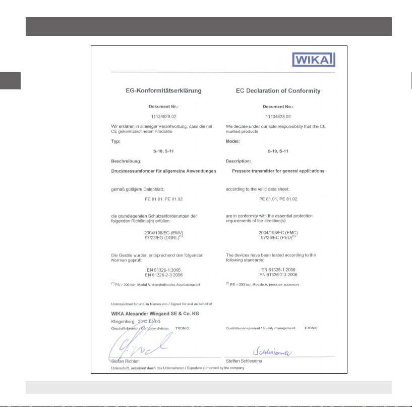
Appendix 1: EC Declaration of conformity model S-11
GB
26 WIKA operating instructions pressure transmitter, model S-11
14043046.01 06/2012 GB/D/F/E
Page 27
Inhalt
Inhalt
1. Allgemeines 28
2. Sicherheit 30
3. Technische Daten 33
4. Aufbau und Funktion 39
5. Transport, Verpackung und Lagerung 39
6. Inbetriebnahme, Betrieb 40
7. Einstellung Nullpunkt und Spanne 45
8. Wartung und Reinigung 46
9. Störungen 47
10. Demontage, Rücksendung und Entsorgung 48
11. Zubehör 49
12. Anlage 1: EG-Konformitätserklärung Typ S-11 50
Konformitätserklärungen nden Sie online unter www.wika.de.
14043046.01 06/2012 GB/D/F/E
D
27WIKA Betriebsanleitung Druckmessumformer, Typ S-11
Page 28

1. Allgemeines
1. Allgemeines
■
Der in der Betriebsanleitung beschriebene Druckmessumformer wird nach den neuesten Erkenntnissen konstruiert und gefertigt.
Alle Komponenten unterliegen während der Fertigung strengen Qualitäts- und Umweltkriterien.
Unsere Managementsysteme sind nach ISO 9001 und ISO 14001 zertiziert.
D
■
Diese Betriebsanleitung gibt wichtige Hinweise zum Umgang mit dem Gerät. Voraussetzung für
sicheres Arbeiten ist die Einhaltung aller angegebenen Sicherheitshinweise und Handlungsanweisungen.
■
Die für den Einsatzbereich des Gerätes geltenden örtlichen Unfallverhütungsvorschriften und allgemeinen Sicherheitsbestimmungen einhalten.
■
Die Betriebsanleitung ist Produktbestandteil und muss in unmittelbarer Nähe des Gerätes für das
Fachpersonal jederzeit zugänglich aufbewahrt werden.
■
Das Fachpersonal muss die Betriebsanleitung vor Beginn aller Arbeiten sorgfältig durchgelesen und
verstanden haben.
■
Die Haftung des Herstellers erlischt bei Schäden durch bestimmungswidrige Verwendung, Nichtbeachten dieser Betriebsanleitung, Einsatz ungenügend qualizierten Fachpersonals sowie eigenmächtiger Veränderung am Gerät.
■
Es gelten die allgemeinen Geschäftsbedingungen in den Verkaufsunterlagen.
■
Technische Änderungen vorbehalten.
■
Weitere Informationen:
- Internet-Adresse: www.wika.de / www.wika.com
- zugehöriges Datenblatt: PE 81.02
- Anwendungsberater:
Tel.: (+49) 9372/132-8976
Fax: (+49) 9372/132-8008976
E-Mail: support-tronic@wika.de
28 WIKA Betriebsanleitung Druckmessumformer, Typ S-11
14043046.01 06/2012 GB/D/F/E
Page 29
1. Allgemeines
Symbolerklärung
WARNUNG!
… weist auf eine möglicherweise gefährliche Situation hin, die zum Tod oder zu schweren
Verletzungen führen kann, wenn sie nicht gemieden wird.
VORSICHT!
… weist auf eine möglicherweise gefährliche Situation hin, die zu geringfügigen oder
leichten Verletzungen bzw. Sach- und Umweltschäden führen kann, wenn sie nicht
gemieden wird.
Information
… hebt nützliche Tipps und Empfehlungen sowie Informationen für einen ezienten und
störungsfreien Betrieb hervor.
VORSICHT!
… weist auf eine möglicherweise gefährliche Situation hin, die durch heiße Oberächen
oder Flüssigkeiten zu Verbrennungen führen kann, wenn sie nicht gemieden wird.
Abkürzungen
2-Leiter Die zwei Anschlussleitungen dienen zur Spannungsversorgung.
Der Speisestrom ist das Messsignal.
3-Leiter Zwei Anschlussleitungen dienen zur Spannungsversorgung.
Eine Anschlussleitung dient für das Messsignal.
U
+
U
-
S
+
Positiver Versorgungsanschluss
Bezugspotential
Analogausgang
D
14043046.01 06/2012 GB/D/F/E
29WIKA Betriebsanleitung Druckmessumformer, Typ S-11
Page 30
2. Sicherheit
2. Sicherheit
WARNUNG!
Vor Montage, Inbetriebnahme und Betrieb sicherstellen, dass der richtige Druckmessumformer
hinsichtlich Messbereich, Ausführung und spezischen Messbedingungen ausgewählt
D
2.1 Bestimmungsgemäße Verwendung
Der Druckmessumformer dient zum Umwandeln von Druck in ein elektrisches Signal im Innen- und
Außenbereich.
Das Gerät ist ausschließlich für den hier beschriebenen bestimmungsgemäßen Verwendungszweck
konzipiert und konstruiert und darf nur dementsprechend verwendet werden.
Die technischen Spezikationen in dieser Betriebsanleitung sind einzuhalten. Eine unsachgemäße
Handhabung oder ein Betreiben des Druckmessumformers außerhalb der technischen Spezikationen
macht die sofortige Stilllegung und Überprüfung durch einen autorisierten WIKA-Servicemitarbeiter
erforderlich.
Ansprüche jeglicher Art aufgrund von nicht bestimmungsgemäßer Verwendung sind ausgeschlossen.
wurde.
Bei Nichtbeachten können schwere Körperverletzungen und/oder Sachschäden auftreten.
WARNUNG!
■
Anschlüsse nur im drucklosen Zustand önen.
■
Betriebsparameter gemäß Kapitel 3 „Technische Daten“ beachten.
■
Druckmessumformer immer innerhalb der Überlast-Druckgrenze betreiben.
Weitere wichtige Sicherheitshinweise benden sich in den einzelnen Kapiteln dieser
Betriebsanleitung.
30 WIKA Betriebsanleitung Druckmessumformer, Typ S-11
14043046.01 06/2012 GB/D/F/E
Page 31
2. Sicherheit
2.2 Personalqualikation
WARNUNG!
Verletzungsgefahr bei unzureichender Qualikation!
Unsachgemäßer Umgang kann zu erheblichen Personen- und Sachschäden führen.
Die in dieser Betriebsanleitung beschriebenen Tätigkeiten nur durch Fachpersonal nachfolgend beschriebener Qualikation durchführen lassen.
Fachpersonal
Das Fachpersonal ist aufgrund seiner fachlichen Ausbildung, seiner Kenntnisse der Mess- und
Regelungstechnik und seiner Erfahrungen sowie Kenntnis der landesspezischen Vorschriften,
geltenden Normen und Richtlinien in der Lage, die beschriebenen Arbeiten auszuführen und mögliche
Gefahren selbstständig zu erkennen.
Spezielle Einsatzbedingungen verlangen weiteres entsprechendes Wissen, z. B. über aggressive Medien.
2.3 Besondere Gefahren
WARNUNG!
Bei gefährlichen Messstoen wie z. B. Sauersto, Acetylen, brennbaren oder giftigen
Stoen, sowie bei Kälteanlagen, Kompressoren etc. müssen über die gesamten allgemeinen
Regeln hinaus die einschlägigen Vorschriften beachtet werden.
WARNUNG!
Messstoreste im ausgebauten Druckmessumformer können zur Gefährdung von
Personen, Umwelt und Einrichtung führen.
Ausreichende Vorsichtsmaßnahmen ergreifen.
D
Dieses Gerät nicht in Sicherheits- oder in Not-Aus-Einrichtungen benutzen. Fehlerhafte
Anwendungen des Gerätes können zu Verletzungen führen.
Am Gerät können im Fehlerfall aggressive Medien mit extremer Temperatur und unter
hohem Druck oder Vakuum anliegen.
14043046.01 06/2012 GB/D/F/E
31WIKA Betriebsanleitung Druckmessumformer, Typ S-11
Page 32

2. Sicherheit
2.4 Beschilderung / Sicherheitskennzeichnungen
Typenschild
D
Messbereich
Ausgangssignal
Hilfsenergie
S# Serien-Nr.
P# Erzeugnis-Nr.
Wird die Seriennummer und der 2D-Code durch mechanische Beschädigung oder Übermalen
unleserlich, ist eine Rückverfolgbarkeit nicht mehr möglich.
Symbolerklärung
CSA, Canadian Standard Association
Das Gerät wurde durch CSA International geprüft und zertiziert.
Geräte mit dieser Kennzeichnung stimmen überein mit den anwendbaren kanadischen
Normen zur Sicherheit.
GOST, Gossudarstwenny Standart (Государственный Стандарт)
GOST-R (mark)
Geräte mit dieser Kennzeichnung stimmen überein mit den anwendbaren nationalen
Sicherheitsbestimmungen von Russland (Russische Föderation).
CE, Communauté Européenne
Geräte mit dieser Kennzeichnung stimmen überein mit den zutreenden europäischen
Richtlinien.
32 WIKA Betriebsanleitung Druckmessumformer, Typ S-11
®
Zulassungen
Anschlussbelegung
2D-Code
14043046.01 06/2012 GB/D/F/E
Page 33

3. Technische Daten
3. Technische Daten
3.1 Messbereiche
Relativdruck
bar Messbereich 0 ... 0,1 0 ... 0,16 0 ... 0,25 0 ... 0,4 0 ... 0,6 0 ... 1 0 ... 1,6
Überlast-Druckgrenze 1 1,5 2 2 4 5 10
Berstdruck 2 2 2,4 2,4 4,8 6 12
Messbereich 0 ... 2,5 0 ... 4 0 ... 6 0 ... 10 0 ... 16 0 ... 25 0 ... 40
Überlast-Druckgrenze 10 17 35 35 80 50 80
Berstdruck 12 20,5 42 42 96 96 400
Messbereich 0 ... 60 0 ... 100 0 ... 160 0 ... 250 0 ... 400 0 ... 600
Überlast-Druckgrenze 120 200 320 500 800 1.200
Berstdruck 550 600 600 600 1.600 1.600
Absolutdruck
bar Messbereich 0 ... 0,25 0 ... 0,4 0 ... 0,6 0 ... 1 0 ... 1,6 0 ... 2,5 0 ... 4
Überlast-Druckgrenze 2 2 4 5 10 10 17
Berstdruck 2,4 2,4 4,8 6 12 12 20,5
Messbereich 0 ... 6 0 ... 10 0 ... 16
Überlast-Druckgrenze 35 35 80
Berstdruck 42 42 96
Vakuum- und +/- Messbereich
bar Messbereich -0,1 ... 0 -0,16 ... 0 -0,25 ... 0 -0,4 ... 0 -0,6 ... 0 -1 ... 0 -1 ... +0,6
Überlast-Druckgrenze 1 1,5 2 2 4 5 10
Berstdruck 2 2 2,4 2,4 4,8 6 12
Messbereich -1 ... +1,5 -1 ... +3 -1 ... +5 -1 ... +9 -1 ... +15 -1 ... +24
Überlast-Druckgrenze 10 17 35 35 80 50
Berstdruck 12 20,5 42 42 96 96
D
14043046.01 06/2012 GB/D/F/E
33WIKA Betriebsanleitung Druckmessumformer, Typ S-11
Page 34

3. Technische Daten
Vakuumfestigkeit
Ja
3.2 Ausgangssignale
Signalart Signal
D
Strom (2-Leiter) 4 ... 20 mA
Strom (3-Leiter) 0 ... 20 mA
Spannung (3-Leiter) DC 0 ... 10 V
Je nach Signalart gelten folgende Bürden:
Signalart Bürde in Ω
Strom (2-Leiter) ≤ (Hilfsenergie - 10 V) / 0,02 A
Strom (3-Leiter) ≤ (Hilfsenergie - 3 V) / 0,02 A
Spannung (3-Leiter) > maximales Ausgangssignal / 1 mA
3.3 Spannungsversorgung
Hilfsenergie
Die zulässige Hilfsenergie ist vom jeweiligen Ausgangssignal abhängig.
Ausgangssignal Hilfsenergie
4 ... 20 mA (2-Leiter) DC 10 ...30 V
0 ... 20 mA (3-Leiter) DC 10 ...30 V
DC 0 ... 10 V DC 14 ... 30 V
DC 0 ... 5 V DC 10 ...30 V
DC 0 ... 5 V
34 WIKA Betriebsanleitung Druckmessumformer, Typ S-11
14043046.01 06/2012 GB/D/F/E
Page 35

3. Technische Daten
3.4 Genauigkeit
Genauigkeit bei Raumtemperatur
■
Standard: ≤ ±0,5 % der Spanne
■
Option: ≤ ±0,25 % der Spanne
1) Nur für Messbereiche ≥ 0,25 bar
Einschließlich Nichtlinearität, Hysterese, Nullpunkt- und Endwertabweichung (entspricht Messabweichung nach IEC 61298-2). Kalibriert bei senkrechter Einbaulage mit Prozessanschluss nach unten.
Nichtlinearität (nach IEC 61298-2)
≤ ±0,2 % der Spanne BFSL
Nichtwiederholbarkeit
≤ ±0,1 % der Spanne
Temperaturfehler im Nenntemperaturbereich
Nenntemperaturbereich: 0 ... 80 °C
Mittlerer Temperaturkoezient des Nullpunktes
■
≤ 0,2 % der Spanne/10 K
■
< 0,4 % der Spanne/10 K
1) Gilt für Messbereiche ≤ 0,25 bar
1)
Mittlerer Temperaturkoezient der Spanne
■
≤ 0,2 % der Spanne/10 K
1)
D
Einschwingzeit
≤ 10 ms
Langzeitdrift
≤ ±0,2 % der Spanne/Jahr
14043046.01 06/2012 GB/D/F/E
35WIKA Betriebsanleitung Druckmessumformer, Typ S-11
Page 36

3. Technische Daten
Einstellbarkeit Nullpunkt und Spanne
1)
Einstellung erfolgt über Potentiometer im Gerät.
■
Nullpunkt ± 5 %
■
Spanne ± 5 %
1) Einstellung bei Kabelausgang mit Schutzart IP 68 nicht möglich
D
3.5 Einsatzbedingungen
Schutzarten (nach IEC 60529)
Die Schutzart ist abhängig vom Typ des elektrischen Anschlusses.
Elektrischer Anschluss Schutzart
Winkelstecker DIN 175301-803 A IP 65
Rundstecker M12 x 1 (4-polig) IP 67
Kabelausgang
■
Standard
■
Option
1) Einstellbarkeit Nullpunkt und Spanne nicht möglich
IP 67
IP 68
1)
Die angegebenen Schutzarten gelten nur im gesteckten Zustand mit Gegensteckern entsprechender
Schutzart.
Vibrationsfestigkeit
■
Prozessanschlüsse ohne Kühlstrecke
20 g (IEC 60068-2-6, bei Resonanz)
■
Prozessanschlüsse mit Kühlstrecke
10 g (IEC 60068-2-6, bei Resonanz)
36 WIKA Betriebsanleitung Druckmessumformer, Typ S-11
14043046.01 06/2012 GB/D/F/E
Page 37

3. Technische Daten
Schockfestigkeit
■
Prozessanschlüsse ohne Kühlstrecke
1.000 g (IEC 60068-2-27, mechanisch)
■
Prozessanschlüsse mit Kühlstrecke
400 g (IEC 60068-2-27, mechanisch)
Zulässige Temperaturbereiche
Prozessanschlüsse ohne Kühlstrecke
Umgebung -20 ... +80 °C
Lagerung -40 ... +100 °C
1)
Medium
■
Standard -30 ... +100 °C
■
Option -30 ... +125 °C
1) Für Messbereiche 0 ... 400 und 0 ... 600 bar, ist die Medientemperatur auf -30 ... +70 °C beschränkt.
2) Bei senkrechter Einbaulage muss die Messstelle isoliert sein, um Einüsse durch Wärmestrahlung und Konvektion zu vermeiden.
3.6 Elektrische Anschlüsse
Kurzschlussfestigkeit
S+ gegen U-
Verpolschutz
U+ gegen U-
Überspannungsschutz
DC 36 V
Prozessanschlüsse mit Kühlstrecke
Umgebung -20 ... +80 °C
Lagerung -40 ... +100 °C
Medium
1) 2)
-20 ... +150 °C
D
Isolationsspannung
DC 500 V bei NEC Class 02 Spannungsversorgung (Niederspannung und Niederstrom max. 100 VA
auch im Fehlerzustand)
14043046.01 06/2012 GB/D/F/E
37WIKA Betriebsanleitung Druckmessumformer, Typ S-11
Page 38

3. Technische Daten
3.7 Prozessanschlüsse
Prozessanschluss Verfügbare Messbereiche
G ½ B frontbündig
G 1 B frontbündig
D
Hygienic G 1 B frontbündig 0 ... 0,1 bis 0 ... 25 bar
3.8 Werkstoe
Messstoberührte Teile
CrNi-Stahl
Dichtwerkstoe siehe Tabelle
Prozessanschluss Standard Option
ohne Kühlstrecke NBR
mit Kühlstrecke FPM/FKM EPDM
Hygienic EPDM -
Nicht messstoberührte Teile
Interne Druckübertragungsüssigkeit
■
Standard: Synthetisches Öl
■
Option: Lebensmitteltaugliche Druckübertragungsüssigkeit gemäß FDA 21 CFR 178.3750
1)
1)
0 ... 2,5 bis 0 ... 600 bar
0 ... 0,1 bis 0 ... 1,6 bar
■
FPM/FKM
■
EPDM
3.9 Zulassungen, Richtlinien und Zertikate
Zulassung
■
CSA
■
GOST
38 WIKA Betriebsanleitung Druckmessumformer, Typ S-11
14043046.01 06/2012 GB/D/F/E
Page 39

3. Technische Daten / ... / 5. Transport, Verpackung und ...
CE-Konformität
■
EMV-Richtline 2004/108/EG EN 61326 Emission (Gruppe 1, Klasse B) und Störfestigkeit (industrieller Bereich)
■
Druckgeräterichtlinie 97/23/EG
Bei Sondertypennummer, z. B. S-11000 Spezikationen gemäß Lieferschein beachten.
Weitere technische Daten siehe WIKA Datenblatt PE 81.02 und Bestellunterlagen.
4. Aufbau und Funktion
4.1 Beschreibung
Der anstehende Druck wird mittels Membranverformung am Sensorelement gemessen. Unter Zuführung von Hilfsenergie wird diese Membranverformung in ein elektrisches Signal umgewandelt. Das vom
Druckmessumformer ausgegebene Signal ist verstärkt und standardisiert. Das Ausgangssignal verhält
sich proportional zum gemessenen Druck.
4.2 Lieferumfang
Lieferumfang mit dem Lieferschein abgleichen.
5. Transport, Verpackung und Lagerung
5.1 Transport
Druckmessumformer auf eventuell vorhandene Transportschäden untersuchen.
Oensichtliche Schäden unverzüglich mitteilen.
5.2 Verpackung
Verpackung erst unmittelbar vor der Montage entfernen.
Die Verpackung aufbewahren, denn diese bietet bei einem Transport einen optimalen Schutz
(z. B. wechselnder Einbauort, Reparatursendung).
14043046.01 06/2012 GB/D/F/E
D
39WIKA Betriebsanleitung Druckmessumformer, Typ S-11
Page 40

5. Transport, Verpackung ... / 6. Inbetriebnahme, Betrieb
5.3 Lagerung
Zulässige Bedingungen am Lagerort:
■
Lagertemperatur: siehe Kapitel 3 „Technische Daten“
■
Feuchtigkeit: 45 ... 75 % relative Feuchte
Folgende Einüsse vermeiden:
D
■
Mechanische Vibration, mechanischer Schock (hartes Aufstellen)
■
Ruß, Dampf, Staub und korrosive Gase
■
Explosionsgefährdete Umgebung, entzündliche Atmosphären
Den Druckmessumformer in der Originalverpackung an einem Ort lagern, der die oben gelisteten
Bedingungen erfüllt. Wenn die Originalverpackung nicht vorhanden ist, dann das Gerät wie folgt verpacken und lagern:
1. Schutzkappe auf dem Prozessanschluss aufbringen
2. Das Gerät mit dem Dämmmaterial in der Verpackung platzieren.
WARNUNG!
Vor der Einlagerung des Gerätes (nach Betrieb) alle anhaftenden Messstoreste entfernen.
Dies ist besonders wichtig, wenn der Messsto gesundheitsgefährdend ist, wie z. B. ätzend,
giftig, krebserregend, radioaktiv, usw.
6. Inbetriebnahme, Betrieb
VORSICHT!
Vor der Inbetriebnahme den Druckmessumformer optisch prüfen.
■
Auslaufende Flüssigkeit weist auf eine Beschädigung hin.
■
Die Membrane des Prozessanschlusses auf Beschädigungen überprüfen.
■
Den Druckmessumformer nur in sicherheitstechnisch einwandfreiem Zustand einsetzen.
40 WIKA Betriebsanleitung Druckmessumformer, Typ S-11
14043046.01 06/2012 GB/D/F/E
Page 41

6. Inbetriebnahme, Betrieb
6.1 Mechanische Montage
■
Schutzkappe erst kurz vor dem Einbau entfernen.
■
Sicherstellen, dass die Membrane des Prozessanschlusses während
des Einbaus nicht beschädigt wird.
■
Dichtächen am Druckmessumformer und der Messstelle müssen
stets frei von Verschmutzungen sein.
■
Das Gerät nur über die Schlüsselächen ein- bzw. ausschrauben.
Niemals das Gehäuse oder die Kühlstrecke als Angrisäche
verwenden.
■
Das richtige Drehmoment ist abhängig von der Dimension des
Prozessanschlusses sowie der verwendeten Dichtung (Form/
Werksto).
■
Beim Einschrauben die Gewindegänge nicht verkanten.
■
Angaben zu Einschraublöchern und Einschweißstutzen siehe
Technische Information IN 00.14 unter www.wika.de.
■
Stecker aufstecken und handfest verschrauben. Die Montage des Winkelsteckers wird in Kapitel 6.2
„ Elektrische Montage“ beschrieben.
Abdichtung
Zur Abdichtung der Prozessanschlüsse mit zylindrischem
Gewinde an der Dichtäche
sind Flachdichtungen, Dichtlin-
Zylindrisches Gewinde Kegeliges Gewinde
nach EN 837 nach DIN 3852-E
sen oder WIKA-Proldichtungen
einzusetzen.
Bei kegeligem
Gewinde (z. B. NPT-Gewinde)
erfolgt die Abdichtung im Gewinde
, mit zusätzlichen Dichtwerkstoen, wie z.B. PTFE-Band (EN 837-2).
Schlüsseläche
NPT, R und PT
D
Hinweise zu Dichtungen siehe WIKA Datenblatt AC 09.08 oder unter www.wika.de.
14043046.01 06/2012 GB/D/F/E
41WIKA Betriebsanleitung Druckmessumformer, Typ S-11
Page 42

6. Inbetriebnahme, Betrieb
Abmessungen der Prozessanschlüsse in mm
D
G D1 L1 L2 L3 L4
G ½ B 18 23 20,5 10 15,5
G D1 L1 L2 L3 L4
G 1 B Hygienic 29,5 28 25 9 15,5
42 WIKA Betriebsanleitung Druckmessumformer, Typ S-11
G D1 L1 L2 L3 L4
G 1 B 30 23 20,5 10 15,5
Angaben zu Einschraublöchern und Einschweißstutzen siehe Technische Information IN 00.14
unter www.wika.de.
14043046.01 06/2012 GB/D/F/E
Page 43
6. Inbetriebnahme, Betrieb
6.2 Elektrische Montage
■
Das Gerät über den Prozessanschluss erden.
■
Geräte mit Spannungsausgang mit geschirmter Leitung betreiben und den Schirm auf mindestens
einer Leitungsseite erden, wenn die Leitungen länger als 30 m sind oder das Gebäude verlassen.
■
In Nordamerika das Gerät über „Class 2 Circuits“ oder „Class 2 Power Units“ gemäß CEC ( Canadian Electrical Code) oder NEC (National Electrical Code) betreiben.
■
Den Kabeldurchmesser passend zur Kabeldurchführung des Steckers wählen. Darauf achten, dass
die Kabelverschraubung des montierten Steckers korrekt sitzt und dass die Dichtungen vorhanden
und nicht beschädigt sind. Verschraubung festziehen und den korrekten Sitz der Dichtungen
überprüfen, um die Schutzart zu gewährleisten.
■
Bei Kabelausgängen sicherstellen, dass am Ende des Kabels keine Feuchtigkeit eintritt.
Anschlussschemen
Winkelstecker DIN 175301-803 A
2-Leiter 3-Leiter
U+1 1
U-2 2
- 3
S
+
Aderquerschnitt max. 1,5 mm
Kabeldurchmesser 6 ... 8 mm
2
Rundstecker M12 x 1 (4-polig)
2-Leiter 3-Leiter
U+1 1
U-3 3
- 4
S
+
Kabelausgang, ungeschirmt
2-Leiter 3-Leiter
U+braun braun
U-grün grün
- weiß
S
+
Aderquerschnitt 3 x 0,5 mm
Kabeldurchmesser 6,8 mm
Kabellängen 1,5 m, 3 m, 5 m, 10 m, 15 m
2
D
14043046.01 06/2012 GB/D/F/E
43WIKA Betriebsanleitung Druckmessumformer, Typ S-11
Page 44

6. Inbetriebnahme, Betrieb
Montage Winkelstecker DIN 175301-803
1. Die Schraube lösen.
2. Die Kabelverschraubung lösen.
3. Die Winkeldose + vom Gerät abziehen.
D
4. Über die Montageönung den Klemmblock aus dem
Gehäuse hebeln.
5. Das Kabel mit passendem Leitungsaußendurchmesser (siehe
„Anschlussschemen“) durch Kabelverschraubung , Ring ,
Dichtung und das Gehäuse schieben.
6. Die Kabelenden entsprechend der Belegung in den
Anschlussklemmen des Klemmblocks anschließen
(Belegung siehe „Anschlussschemen“).
7. Den Klemmblock in das Gehäuse drücken.
8. Das Kabel über die Kabelverschraubung verschrauben.
Darauf achten, dass die Kabelverschraubung und Dichtung
unbeschädigt ist und korrekt sitzt, um die Schutzart zu
gewährleisten.
9. Die quadratische Flachdichtung über die Anschlusspins des
Druckmessumformers legen.
10. Die montiere Winkeldose + auf die Anschlusspins des
Druckmessumformers schieben.
11. Über die Schraube die Winkeldose am Druckmessumformer
handfest verschrauben.
Montageönung
44 WIKA Betriebsanleitung Druckmessumformer, Typ S-11
14043046.01 06/2012 GB/D/F/E
Page 45

7. Einstellung Nullpunkt und Spanne
7. Einstellung Nullpunkt und Spanne
Das Potentiometer zur Spanneeinstellung nur verstellen, wenn eine Kalibrierausstattung
vorhanden ist, die mindestens die dreifache Genauigkeit des Druckmessumformers
aufweist.
7.1 Vorbereitung (Abbildung A)
Um Zugang zu den Potentiometern zu erhalten, das Gerät wie folgt
önen:
■
Den elektrischen Anschluss vom Gerät trennen.
■
Den Griring lösen.
■
Den Gerätestecker vorsichtig aus dem Gerät ziehen.
■
Den Gerätestecker gemäß Anschlussschema mit der
Hilfsenergie und einer Anzeigeeinheit (z. B. Strommessgerät,
Spannungsmessgerät) verbinden.
7.2 Einstellung Nullpunkt (Abbildung B)
■
Den Messbereichsanfang anfahren.
■
Über das Potentiometer „Z“ das minimale Ausgangssignal justieren (z. B. 4 mA)
D
A
7.3 Einstellung Spanne (Abbildung B)
■
Den Messbereichsendwert anfahren.
■
Über das Potentiometer „S“ das maximale Ausgangssignal
justieren (z. B. 20 mA).
■
Den Nullpunkt überprüfen und bei Abweichung erneut justieren.
■
Den Vorgang solange wiederholen bis Nullpunkt und Spanne
korrekt eingestellt sind.
14043046.01 06/2012 GB/D/F/E
B
45WIKA Betriebsanleitung Druckmessumformer, Typ S-11
Page 46

7. Einstellung Nullpunkt und Spanne / 8. Wartung und Reinigung
7.4 Einstellung abschließen (Abbildung A)
■
Den Gerätestecker von der Hilfsenergie und Anzeigeeinheit trennen.
■
Den Gerätestecker vorsichtig in das Gerät stecken, ohne Litzen und Dichtungen zu beschädigen.
Die Dichtungen müssen sauber und unbeschädigt sein, um die angegebene Schutzart sicherzustellen.
■
Den Griring festziehen.
D
Nach dem Justieren die korrekte Arbeitsweise des Systems überprüfen.
Empfohlener Nachkalibrierzyklus: 1 Jahr
8. Wartung und Reinigung
8.1 Wartung
Der Druckmessumformer ist wartungsfrei.
Reparaturen sind ausschließlich vom Hersteller durchzuführen.
8.2 Reinigung
VORSICHT!
■
Vor der Reinigung das Gerät ordnungsgemäß von der Druckversorgung trennen,
ausschalten und von der Hilfsenergie trennen.
■
Keine spitzen bzw. harten Gegenstände zur Reinigung verwenden, denn diese können
die Membrane des Prozessanschlusses beschädigen.
■
Das Gerät mit einem feuchten Tuch reinigen.
■
Elektrische Anschlüsse nicht mit Feuchtigkeit in Berührung bringen.
■
Ausgebautes Gerät vor der Rücksendung spülen bzw. säubern, um Personen und
Umwelt vor Gefährdung durch anhaftende Messstoreste zu schützen.
■
Messstoreste am ausgebauten Druckmessumformer können zur Gefährdung von
Personen, Umwelt und Einrichtung führen.
Ausreichende Vorsichtsmaßnahmen ergreifen.
Hinweise zur Rücksendung des Gerätes siehe Kapitel 10.2 „Rücksendung“.
46 WIKA Betriebsanleitung Druckmessumformer, Typ S-11
14043046.01 06/2012 GB/D/F/E
Page 47

9. Störungen
9. Störungen
Bei Störungen zuerst überprüfen, ob der Druckmessumformer mechanisch und elektrisch korrekt
montiert ist.
Störung Mögliche Ursache Maßnahme
Kein Ausgangssignal Leitungsbruch
Keine/Falsche Hilfsenergie
Kein/Falsches Ausgangssignal Verdrahtungsfehler Verdrahtung korrigieren
Gleichbleibendes Ausgangs-
signal bei Druckänderung
Signalspanne zu klein/fällt ab Mechanische Überlastung durch Überdruck
Signalspanne schwankend/
ungenau
Abweichendes Nullpunktsignal Zu hohe/niedrige Einsatztemperaturen
14043046.01 06/2012 GB/D/F/E
Mechanische Überlastung durch Überdruck Gerät austauschen
Membranbeschädigung
Dichtung/Dichtäche beschädigt/
verschmutzt, Dichtung sitzt nicht korrekt,
Gewindegänge verkantet
EMV-Störquellen in Umgebung (z. B.
Frequenzumrichter)
Zu hohe/niedrige Einsatztemperaturen
Gerät nicht geerdet
Stark schwankender Druck des Prozess-
mediums
Abweichende Einbaulage
Überlast-Druckgrenze überschritten
Durchgang überprüfen
Hilfsenergie korrigieren
Gerät austauschen
Gerät austauschen
Dichtung/Dichtäche säubern, Dichtung austauschen
Gerät abschirmen, Leitung
abschirmen, Störquelle entfernen
Zulässige Temperaturen einhalten
Gerät erden
Dämpfung; Beratung durch Hersteller
Zulässige Temperaturen einhalten
Nullpunkt korrigieren
Gerät austauschen
D
47WIKA Betriebsanleitung Druckmessumformer, Typ S-11
Page 48
9. Störungen / 10. Demontage, Rücksendung und Entsorgung
VORSICHT!
Können Störungen mit Hilfe der oben aufgeführten Maßnahmen nicht beseitigt werden, ist
der Druckmessumformer unverzüglich außer Betrieb zu setzen und gegen versehentliche
Inbetriebnahme zu schützen. In diesem Falle Kontakt mit dem Hersteller aufnehmen. Bei
notwendiger Rücksendung die Hinweise unter Kapitel 10.2 „Rücksendung“ beachten.
D
10. Demontage, Rücksendung und Entsorgung
WARNUNG!
Messstoreste am ausgebauten Druckmessumformer können zur Gefährdung von
Personen, Umwelt und Einrichtung führen.
Ausreichende Vorsichtsmaßnahmen ergreifen.
10.1 Demontage
WARNUNG!
Verbrennungsgefahr!
Vor dem Ausbau das Gerät ausreichend abkühlen lassen!
Beim Ausbau besteht Gefahr durch austretende, gefährlich heiße Messstoe.
Druckmessumformer nur im drucklosen Zustand demontieren!
Während der Demontage die Membrane des Prozessanschlusses nicht beschädigen. Schutzkappe
zum Schutz der Membrane nach der Demontage und Reinigung (siehe Kapitel 8.2 „Reinigung“) am
Gerät anbringen.
48 WIKA Betriebsanleitung Druckmessumformer, Typ S-11
14043046.01 06/2012 GB/D/F/E
Page 49

10. Demontage, Rücksendung und Entsorgung / 11. Zubehör
10.2 Rücksendung
WARNUNG!
Beim Versand des Gerätes unbedingt beachten:
Alle an WIKA gelieferten Geräte müssen frei von Gefahrstoen (Säuren, Laugen,
Lösungen, etc.) sein.
Zur Rücksendung des Gerätes die Originalverpackung oder eine geeignete Transportverpackung
verwenden.
Dem Gerät das Rücksendeformular ausgefüllt beifügen.
Das Rücksendeformular bendet sich in der Rubrik 'Service' unter www.wika.de.
10.3 Entsorgung
Durch falsche Entsorgung können Gefahren für die Umwelt entstehen.
Gerätekomponenten und Verpackungsmaterialien entsprechend den landesspezischen
Abfallbehandlungs- und Entsorgungsvorschriften umweltgerecht entsorgen.
11. Zubehör
Bezeichnung Bestell-Nr.
Einschweißstutzen für G ½ B frontbündig 1192299
Einschweißstutzen für G 1 B frontbündig 1192264
Einschweißstutzen für G 1 B Hygienic frontbündig 2166011
D
14043046.01 06/2012 GB/D/F/E
49WIKA Betriebsanleitung Druckmessumformer, Typ S-11
Page 50

Anlage 1: EG-Konformitätserklärung Typ S-11
D
50 WIKA Betriebsanleitung Druckmessumformer, Typ S-11
14043046.01 06/2012 GB/D/F/E
Page 51

Sommaire
Sommaire
1. Généralités 52
2. Sécurité 54
3. Spécications 57
4. Conception et fonction 63
5. Transport, emballage et stockage 63
6. Mise en service, exploitation 64
7. Réglage du point zéro y étendue 69
8. Entretien et nettoyage 70
9. Dysfonctionnements 71
10. Démontage, retour et mise au rebut 72
11. Accessoires 74
12. Annexe 1: Déclaration de conformité CE type S-11 75
Déclarations de conformité se trouvent sur www.wika.fr.
14043046.01 06/2012 GB/D/F/E
F
51WIKA Mode d‘emploi transmetteur de pression, type S-11
Page 52

1. Généralités
1. Généralités
■
Le transmetteur décrit dans le mode d'emploi est conçu et fabriqué selon les dernières technologies
en vigueur. Tous les composants sont soumis à des critères de qualité et d'environnement stricts
durant la fabrication. Nos systèmes de gestion sont certiés selon ISO 9001 et ISO 14001.
■
Ce mode d'emploi donne des indications importantes concernant l'utilisation de l'instrument. Il
est possible de travailler en toute sécurité avec ce produit en respectant toutes les consignes de
F
sécurité et d'utilisation.
■
Respecter les prescriptions locales de prévention contre les accidents et les prescriptions générales
de sécurité en vigueur pour le domaine d‘application de l'instrument.
■
Le mode d'emploi fait partie du produit et doit être conservé à proximité immédiate de l'instrument et
être accessible à tout moment pour le personnel qualié.
■
Le personnel qualié doit, avant de commencer toute opération, avoir lu soigneusement et compris
le mode d'emploi.
■
La responsabilité du fabricant n'est pas engagée en cas de dommages provoqués par une utilisation
non conforme à l'usage prévu, de non respect de ce mode d'emploi, d'utilisation de personnel peu
qualié de même qu'en cas de modications de l'instrument eectuées par l'utilisateur.
■
Les conditions générales de vente mentionnées dans les documents de vente s'appliquent.
■
Sous réserve de modications techniques.
■
Pour obtenir d'autres informations :
- Consulter notre site internet : www.wika.fr
- Fiche technique correspondante : PE 81.02
- Conseiller applications :
Tel. : (+33) 1 343084-84
Fax : (+33) 1 343084-94
E-Mail : info@wika.fr
52 WIKA Mode d'emploi transmetteur de pression, type S-11
14043046.01 06/2012 GB/D/F/E
Page 53

1. Généralités
Explication des symboles
AVERTISSEMENT !
… indique une situation présentant des risques susceptibles de provoquer la mort ou des
blessures graves si elle n'est pas évitée.
ATTENTION !
… indique une situation potentiellement dangereuse et susceptible de provoquer de
légères blessures ou des dommages matériels et pour l'environnement si elle n'est pas
évitée.
Information
… met en exergue les conseils et recommandations utiles de même que les informations
permettant d'assurer un fonctionnement ecace et normal.
ATTENTION !
… indique une situation présentant des risques susceptibles de provoquer des brûlures
dues à des surfaces ou liquides chauds si elle n'est pas évitée.
Abréviations
2 ls Les deux lignes de raccordement servent à l'alimentation en tension.
Le signal de mesure fournit également le courant d'alimentation.
3 ls Deux lignes de raccordement servent à l'alimentation en alimentation
Un câble de raccordement est utilisé pour le signal de mesure.
U
+
U
-
S
+
Borne d'alimentation positive
Potentiel de référence
Sortie analogique
F
14043046.01 06/2012 GB/D/F/E
53WIKA Mode d‘emploi transmetteur de pression, type S-11
Page 54

2. Sécurité
2. Sécurité
AVERTISSEMENT !
Avant le montage, la mise en service et le fonctionnement, s'assurer que le transmetteur
de pression a été choisi de façon adéquate, en ce qui concerne l'étendue de mesure, la
version et les conditions de mesure spéciques.
F
2.1 Utilisation conforme à l'usage prévu
Le transmetteur de pression est utilisé pour convertir la pression en un signal électrique à l'intérieur
comme à l'extérieur.
L'instrument est conçu et construit exclusivement pour une utilisation conforme à l'usage prévu décrit ici
et ne doit être utilisé qu'en conséquence.
Les spécications techniques mentionnées dans ce mode d'emploi doivent être respectées. En cas
d'utilisation inadéquate ou de fonctionnement du transmetteur de pression en dehors des spécications
techniques, un arrêt et contrôle doivent être immédiatement eectués par un collaborateur autorisé du
service de WIKA.
Aucune réclamation ne peut être recevable en cas d'utilisation non conforme à l'usage prévu.
Un non-respect de cette consigne peut entraîner des blessures corporelles graves et/ou
des dégâts matériels.
AVERTISSEMENT !
■
N'ouvrez les connexions qu'après que le système ait été dépressurisé.
■
Observez les conditions de fonctionnement conformément au chapitre 3 "Spécications".
■
Ne faites fonctionner le transmetteur de pression que dans les limites de surpression.
Vous trouverez d'autres consignes de sécurité dans les sections individuelles du présent
mode d'emploi.
54 WIKA Mode d'emploi transmetteur de pression, type S-11
14043046.01 06/2012 GB/D/F/E
Page 55
2. Sécurité
2.2 Qualication du personnel
AVERTISSEMENT !
Danger de blessure en cas de qualication insusante !
Une utilisation non conforme peut entraîner d'importants dommages corporels et matériels.
Les opérations décrites dans ce mode d'emploi ne doivent être eectuées que par un
personnel ayant la qualication décrite ci-après.
Personnel qualié
Le personnel qualié est, en raison de sa formation spécialisée, de ses connaissances dans le domaine
de la technique de mesure et de régulation et de ses expériences de même que de sa connaissance
des prescriptions nationales, des normes et directives en vigueur, en mesure d'eectuer les travaux
décrits et de reconnaître automatiquement les dangers potentiels.
Les conditions d'utilisation spéciales exigent également une connaissance adéquate par exemple des
liquides agressifs.
2.3 Dangers particuliers
AVERTISSEMENT !
Dans le cas de uides de mesure dangereux comme notamment l'oxygène, l'acétylène, les
substances combustibles ou toxiques, ainsi que dans le cas d'installations de réfrigération,
de compresseurs etc., les directives appropriées existantes doivent être observées en plus
de l'ensemble des règles générales.
AVERTISSEMENT !
Les restes de uides se trouvant dans le transmetteur de pression démonté peuvent mettre
en danger les personnes, l'environnement ainsi que l'installation.
Prendre des mesures de sécurité susantes.
Ne pas utiliser cet instrument dans des dispositifs de sécurité ou d'arrêt d'urgence. Une
utilisation incorrecte de l'instrument peut occasionner des blessures.
En cas d'erreur, des uides agressifs peuvent être présents à une température extrême et
sous une pression élevée ou sous vide au niveau de l'instrument.
14043046.01 06/2012 GB/D/F/E
F
55WIKA Mode d‘emploi transmetteur de pression, type S-11
Page 56

2. Sécurité
2.4 Etiquetage / Marquages de sécurité
Plaque signalétique
Homologations
Etendue de mesure
F
Signal de sortie
Alimentation
S# N° Série
P# N° Produit
Conguration du
raccordement
Code 2D
Si le numéro de série et le code 2D deviennent illisible (par ex. à cause de dommages mécaniques ou
de peinture), aucune traçabilité n'est plus possible.
Explication des symboles
CSA, Canadian Standard Association®
L'instrument a été contrôlé et certié par CSA International. En outre, les appareils avec ce
marquage sont conformes aux normes canadiennes et américaines de sécurité applicables.
GOST, Gossudarstwenny Standart (Государственный Стандарт)
GOST-R (marque)
Les instruments qui portent cette marque sont en accord avec les règles nationales de
sécurité russes applicables (Fédération Russe).
CE, Communauté Européenne
Les instruments avec ce marquage sont conformes aux directives européennes pertinentes.
56 WIKA Mode d'emploi transmetteur de pression, type S-11
14043046.01 06/2012 GB/D/F/E
Page 57

3. Spécications
3. Spécications
3.1 Etendues de mesure
Pression relative
bar Etendue de mesure 0 ... 0,1 0 ... 0,16 0 ... 0,25 0 ... 0,4 0 ... 0,6 0 ... 1 0 ... 1,6
Limite de surpression 1 1,5 2 2 4 5 10
Pression d'éclatement 2 2 2,4 2,4 4,8 6 12
Etendue de mesure 0 ... 2,5 0 ... 4 0 ... 6 0 ... 10 0 ... 16 0 ... 25 0 ... 40
Limite de surpression 10 17 35 35 80 50 80
Pression d'éclatement 12 20,5 42 42 96 96 400
Etendue de mesure 0 ... 60 0 ... 100 0 ... 160 0 ... 250 0 ... 400 0 ... 600
Limite de surpression 120 200 320 500 800 1 200
Pression d'éclatement 550 600 600 600 1.600 1.600
Pression absolue
bar Etendue de mesure 0 ... 0,25 0 ... 0,4 0 ... 0,6 0 ... 1 0 ... 1,6 0 ... 2,5 0 ... 4
Limite de surpression 2 2 4 5 10 10 17
Pression d'éclatement 2,4 2,4 4,8 6 12 12 20,5
Etendue de mesure 0 ... 6 0 ... 10 0 ... 16
Limite de surpression 35 35 80
Pression d'éclatement 42 42 96
Vide et étendues de mesure +/-
bar Etendue de mesure -0,1 ... 0 -0,16 ... 0 -0,25 ... 0 -0,4 ... 0 -0,6 ... 0 -1 ... 0 -1 ... +0,6
Limite de surpression 1 1,5 2 2 4 5 10
Pression d'éclatement 2 2 2,4 2,4 4,8 6 12
Etendue de mesure -1 ... +1,5 -1 ... +3 -1 ... +5 -1 ... +9 -1 ... +15 -1 ... +24
Limite de surpression 10 17 35 35 80 50
Pression d'éclatement 12 20,5 42 42 96 96
14043046.01 06/2012 GB/D/F/E
F
57WIKA Mode d‘emploi transmetteur de pression, type S-11
Page 58

3. Spécications
Etanchéité aux vide
Oui
3.2 Signaux de sortie
Type de signal Signal
F
Courant (2 ls) 4 ... 20 mA
Courant (3 ls) 0 ... 20 mA
Tension (3 ls) DC 0 ... 10 V
Selon le type de signal, les charges suivantes s’appliquent :
Type de signal Charge en Ω
Courant (2 ls) ≤ (alimentation - 10 V) / 0,02 A
Courant (3 ls) ≤ (alimentation - 3 V) / 0,02 A
Tension (3 ls) Signal de sortie max. / 1 mA
3.3 Tension d'alimentation
Alimentation
L'alimentation admissible dépend du signal de sortie correspondant.
Signal de sortie Alimentation
4 ... 20 mA (2 ls) DC 10 ...30 V
0 ... 20 mA (3 ls) DC 10 ...30 V
DC 0 ... 10 V DC 14 ... 30 V
DC 0 ... 5 V DC 10 ...30 V
DC 0 ... 5 V
58 WIKA Mode d'emploi transmetteur de pression, type S-11
14043046.01 06/2012 GB/D/F/E
Page 59

3. Spécications
3.4 Précision
Précision à température ambiante
■
Standard : ≤ ± 0,5 % de l'échelle
■
Option: ≤ ± 0,25 % de l'échelle
1) Seulement pour étendues de mesure ≥ 0,25 bar
Incluant la non-linéarité, l'hystérésis, les déviations du point zéro et de valeur nale (correspond à
l'erreur de mesure selon CEI 61298-2). Calibré en position de montage verticale avec le raccord
process regardant vers le bas.
Non-linéarité (CEI 61298-2)
≤ ± 0,2 % de l'échelle BFSL
Non-répétabilité
≤ ± 0,1 % de l'échelle
Erreur de température dans la plage de température nominale
Température nominale: 0 ... 80 °C
Coecient de température moyen du point zéro
■
≤ ± 0,2 % de l'échelle / 10 K
■
< 0,4 % de l'échelle / 10 K
1) S'applique à quelques étendues de mesure ≤ 0,25 bar
Coecient de température moyen de l'échelle
■
≤ ± 0,2 % de l'échelle / 10 K
1)
F
Durée de réglage
≤ 10 ms
Dérive à long terme
≤ ± 0,2 % de l'échelle par an
14043046.01 06/2012 GB/D/F/E
59WIKA Mode d‘emploi transmetteur de pression, type S-11
Page 60

3. Spécications
Possibilité de réglage du point zéro et étendue
1)
Réglage est fait en utilisant potentiomètres à l'intérieur de l'instrument.
Point zéro ± 5 %
L'échelle ± 5 %
1) Réglage pas possible pour un sortie de câble avec un indice de protection IP 68
F
3.5 Conditions de fonctionnement
Indice de protection (selon CEI 60529)
Le degré de protection dépend du type de connexion électrique.
Raccordement électrique Indice de protection
Connecteur coudé DIN 175301-803 A IP 65
Connecteur M12 x 1 (4-plots) IP 67
Sortie câble
■
Standard IP 67
■
Option IP 68
1) Possibilité de réglage du point zéro et étendue pas faisible
1)
L'indice de protection mentionné n’est valable que lorsque le contre-connecteur auquel est raccordé la
sonde de température possède également l'indice de protection requis.
Résistance aux vibrations
■
Raccords process sans élément de refroidissement
20 g (CEI 60068-2-6, sous résonance)
■
Raccords process avec élément de refroidissement
10 g (CEI 60068-2-6, sous résonance)
60 WIKA Mode d'emploi transmetteur de pression, type S-11
14043046.01 06/2012 GB/D/F/E
Page 61

3. Spécications
Résistance aux chocs
■
Raccords process sans élément de refroidissement
1 000 g (CEI 60068-2-27, mécanique)
■
Raccords process avec élément de refroidissement
400 g (CEI 60068-2-27, mécanique)
Plages de température admissibles
Raccords process sans élément de
refroidissement
Ambiante -20 ... +80 °C
Stockage -40 ... +100 °C
1)
Fluide
■
Standard -30 ... +100 °C
■
Option -30 ... +125 °C
1) Pour étendues de mesure 0 ... 400 et 0 ... 600 bar, la température du uide est limitée à -30 ... +70 °C.
2) En position de montage verticale, le point de mesure doit être isolé pour éviter l'inuence d'un rayonnement de chaleur et d'une
convection.
Raccords process avec élément de
refroidissement
Ambiante -20 ... +80 °C
Stockage -40 ... +100 °C
Fluide
1)
-20 ... +150 °C
3.6 Raccordements électriques
Résistance court-circuit
S+ vs. U-
Protection contre l'inversion de polarité
U+ vs. U
-
Protection contre la surtension
36 VDC
Tension d'isolement
DC 500 V avec NEC classe 02 alimentation (basse tension et faible courant max. 100 VA même en cas
de défaut).
14043046.01 06/2012 GB/D/F/E
F
61WIKA Mode d‘emploi transmetteur de pression, type S-11
Page 62

3. Spécications
3.7 Raccords process
Raccord process Etendues de mesure disponibles
G ½ B à aeurement frontal
G 1 B à aeuremen frontal
G 1 B hygiénique, à aeurement frontal 0 ... 0,1 à 0 ... 25 bar
F
3.8 Matériaux
Parties en contact avec le uide
■
Acier inox
■
Pour les matériaux des joints d'étanchéité voir le tableau
Raccord process Standard Option
sans élément de refroidissement NBR
avec élément de refroidissement FPM/FKM EPDM
Hygiénique EPDM -
Parties non en contact avec le uide
Liquide de transmission interne
■
Standard : Huile silicone
■
Option: Amortissement de liquide de transmission liquide de transmission par FCA 21 CFR
178.3750
1)
1)
0 ... 2,5 à 0 ... 600 bar
0 ... 0,1 à 0 ... 1,6 bar
■
FPM/FKM
■
EPDM
3.9 Homologations, directives et certicats
Homologation
■
CSA
■
GOST
62 WIKA Mode d'emploi transmetteur de pression, type S-11
14043046.01 06/2012 GB/D/F/E
Page 63

3. Spécications / 4. ... / 5. Transport, emballage et stockage
Conformité CE
■
CEM directive 2004/108/CE, EN61326 émission (groupe 1, classe B) et résistance aux perturbations
(domaine industriel)
■
Directive relative aux équipements sous pression 97/23/EC
Pour les numéros de type spéciaux, par exemple S-11000, prière de tenir compte des spécications
gurant sur la notice de livraison.
Pour de plus amples spécications, voir la che technique WIKA PE 81.02 et la documentation de
commande.
4. Conception et fonction
4.1 Description
La pression de référence est mesurée sur l'élément capteur par la déformation d'une membrane. En
fournissant du courant, on convertit cette déformation de la membrane en un signal électrique. Le signal
de sortie en provenance du transmetteur de pression est amplié et standardisé. Le signal de sortie est
proportionnel à la pression mesurée.
4.2 Détail de la livraison
Comparer le détail de la livraison avec le bordereau de livraison.
5. Transport, emballage et stockage
5.1 Transport
Vérier s'il existe des dégâts sur le transmetteur de pression liés au transport.
Communiquer immédiatement les dégâts constatés.
F
5.2 Emballage
N'enlever l'emballage qu'avant le montage.
Conserver l'emballage, celui-ci ore, lors d'un transport, une protection optimale (par ex. changement de
lieu d'utilisation, renvoi pour réparation).
14043046.01 06/2012 GB/D/F/E
63WIKA Mode d‘emploi transmetteur de pression, type S-11
Page 64

5. Transport, emballage ... / 6. Mise en service, exploitation
5.3 Stockage
Conditions admissibles sur le lieu de stockage :
■
Température de stockage : voir chapitre 3 "Spécications"
■
Humidité : 45 ... 75 % d'humidité relative
Eviter les inuences suivantes :
■
Vibrations mécaniques, chocs mécaniques (mouvements brusques en le posant)
■
Suie, vapeur, poussière et gaz corrosifs
F
■
Environnement présentant des risques d'explosion, atmosphères inammables
Conserver le pression diérentielle dans l'emballage original dans un endroit qui satisfait aux conditions
susmentionnées. Si l'emballage original n'est pas disponible, emballer et stocker l'instrument comme
suit :
1. Mettre le bouchon de protection sur le raccord process
2. Placer l'instrument avec le matériau isolant dans l'emballage.
AVERTISSEMENT !
Enlever tous les restes de uides adhérents avant l'entreposage de l'instrument (après le
fonctionnement). Ceci est particulièrement important lorsque le uide représente un danger
pour la santé, comme p. ex. des substances corrosives, toxiques, cancérogènes, radioactives
etc..
6. Mise en service, exploitation
ATTENTION !
Avant la mise en service, le transmetteur de pression doit être soumis à un contrôle visuel.
■
Une fuite de liquide indique un dommage.
■
Vérier s'il existe des dégâts sur la membrane du raccord process.
■
Le transmetteur de pression ne doit être utilisé qu'en parfait état de sécurité technique.
64 WIKA Mode d'emploi transmetteur de pression, type S-11
14043046.01 06/2012 GB/D/F/E
Page 65

6. Mise en service, exploitation
6.1 Montage mécanique
■
N'enlevez le couvercle de protection que juste avant l'installation.
■
Assurez-vous que la membrane du raccord process n'est pas endommagée pendant l'installation.
■
Les surfaces d'étanchéité sur le transmetteur de pression et le point de
mesure doivent être propres.
■
Ne vissez ou ne dévissez jamais l'instrument que par les surfaces de
clé. Ne jamais utiliser le boîtier ou l'élément de refroidissement comme
surface de travail.
■
Le couple correct dépend des dimensions du raccord process et du
joint utilisé (forme/matériau).
■
Lorsque vous vissez, ne pas croiser les lets.
■
Pour obtenir des informations concernant les trous taraudés et les
embases à souder, voir les Informations techniques IN 00.14 sur www.wika.fr.
■
Attachez le connecteur et vissez-le à fond à la main. L'assemblage du connecteur coudé est décrite
au chapitre 6.2 "Montage électrique".
Etanchéité
Pour assurer l'étanchéité des
raccords process avec letages
Filetage parallèle Filetage conique
Selon EN 837 Selon DIN 3852-E
parallèles à la surface d'étanchéité , il faut utiliser des joints
plats, des bagues d'étanchéité
ou les joints à écrasement WIKA.
Pour les letages coniques (par
exemple letage NPT) l'étanchéité
sur le letage se fait en utilisant en plus un matériau d'étanchéité comme par exemple la bande PTFE
(selon EN 837-2).
Surface de clé
NPT, R et PT
F
Pour obtenir plus d'informations sur le scellage, voir la che de données WIKA AC 09.08 ou
sous www.wika.fr.
14043046.01 06/2012 GB/D/F/E
65WIKA Mode d‘emploi transmetteur de pression, type S-11
Page 66
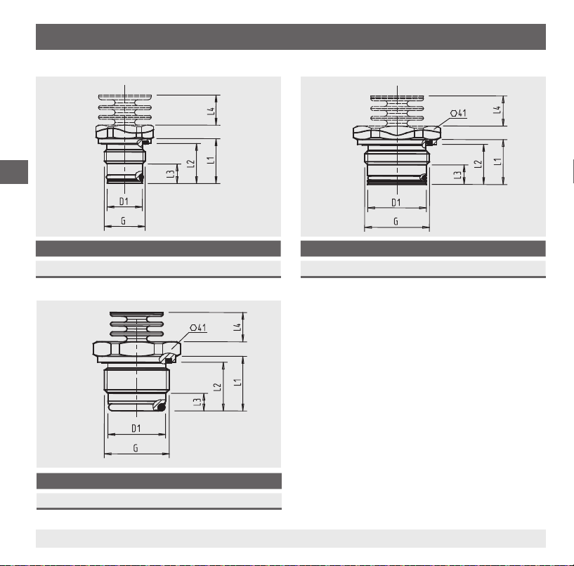
6. Mise en service, exploitation
Dimensions des raccords process en mm
F
G D1 L1 L2 L3 L4
G ½ B 18 23 20,5 10 15,5
G D1 L1 L2 L3 L4
G 1 B hygiénique 29,5 28 25 9 15,5
66 WIKA Mode d'emploi transmetteur de pression, type S-11
G D1 L1 L2 L3 L4
G 1 B 30 23 20,5 10 15,5
Pour obtenir des informations concernant les
trous taraudés et les embases à souder, voir les
Informations techniques IN 00.14 sur www.wika.fr.
14043046.01 06/2012 GB/D/F/E
Page 67

6. Mise en service, exploitation
6.2 Montage électrique
■
L'instrument doit être mis à la terre à l'aide du branchement de process.
■
Pour instruments avec du sortie tension, utiliser un câble blindé, et, si les câbles sont plus longues
que 30 m ou sortent le bâtiment, mettre le blindage à la terre sur au moins une extrémité du câble.
■
En Amérique du Nord, utiliser l'instrument eectué sur "circuits classe 2" ou des "unités de
puissance classe 2" conformément au CEC (Canadian Electrical Code) ou NEC (National Electrical
Code).
■
Choisir un diamètre de câble qui correspond au presse étoupe. Assurez-vous que le passe-câble de
la prise montée est bien serré et que les joints sont bien présents et intacts. Serrer la liaison letée et
vérier que le joint est bien xé pour que l'ensemble soit bien serré.
■
Protéger les départs de câble contre la pénétration d'humidité.
Diagrammes de connexion
Connecteur coudé DIN 175301-803 A
2 ls 3 ls
U+1 1
U-2 2
- 3
S
+
Section du l max. 1,5 mm
Diamètre de câble 6 ... 8 mm
2
Connecteur M12 x 1 (4-plots)
2 ls 3 ls
U+1 1
3 3
U
-
- 4
S
+
Sortie de câble, non blindé
2 ls 3 ls
U+marron marron
U-vert vert
- blanc
S
+
Section du câble 3 x 0,5 mm
Diamètre de câble 6,8 mm
Longueurs de câble 1,5 m, 3 m, 3 m, 10 m, 15 m
2
F
14043046.01 06/2012 GB/D/F/E
67WIKA Mode d‘emploi transmetteur de pression, type S-11
Page 68

6. Mise en service, exploitation
Pose d'un connecteur coudé DIN 175301-803
1. Desserrer la vis .
2. Desserrer le passe-câble .
3. Enlever la prise coudée + de l'instrument.
4. Par le trou de montage , hisser le bloc terminal hors du
boîtier .
F
5. Passer le câble ayant le diamètre extérieur qui convient (voir
"Diagrammes de connexion") à travers le presse-étoupe , la
bague , le joint d'étanchéité et le boîtier .
6. Relier les extrémités de câble aux bornes de raccordement
correspondantes situées sur le bloc terminal en respectant la
distribution des broches (voir "Diagrammes de connexion" pour
la distribution des broches).
7. Presser le bloc terminal dans le boîtier .
8. Serrer le passe-câble autour du câble. Assurez-vous que les
joints ne sont pas endommagés et que le passe-câble et les
joints sont assemblés correctement pour obtenir une protection
contre l'intrusion.
9. Placer le joint plat et carré sur les ches de connexion du
transmetteur de pression.
10. Glisser l'embase coudée assemblée + sur les broches de
raccordement du transmetteur de pression.
11. Au moyen de la vis , visser la prise coudée sur le transmetteur
de pression, serrer à la main.
Trou de montage
68 WIKA Mode d'emploi transmetteur de pression, type S-11
14043046.01 06/2012 GB/D/F/E
Page 69

7. Réglage du point zéro et étendue
7. Réglage du point zéro et étendue
N'ajuster le potentiomètre qui règle l'échelle que si on dispose d'un équipement d'étalonnage ayant au moins trois fois la précision du transmetteur de pression.
7.1 Préparation (Illustration A)
D'accéder au potentiomètre, ouvrir l'instrument comme suit:
■
Déconnecter l'alimentation électrique d'instrument.
■
Éliminer l'écrou de serrage .
■
´Sortez soigneusement la prise d'instrument .
■
Raccorder la prise d'instrument à l'alimentation électrique
et une unité d'achage (par exemple, ampèremètre, voltmètre)
suivant le diagramme de connexion.
7.2 Réglage du point zéro (illustration B)
■
Aller sur le démarrage de l'étendue de mesure.
■
Au moyen du potentiomètre "Z", régler le signal de sortie
minimum (par exemple 4 mA)
7.3 Réglage de l'échelle (illustration B)
■
Aller sur le n de l'étendue de mesure.
■
Au moyen du potentiomètre "S", régler le signal de sortie
maximum (par exemple 20 mA)
■
Vériez le point zéro et s'il y a un écart, corrigez-le.
■
Répéter la procédure jusqu'à ce que le point zéro et l'échelle
soient réglés correctement.
14043046.01 06/2012 GB/D/F/E
A
F
B
69WIKA Mode d‘emploi transmetteur de pression, type S-11
Page 70

7. Réglage du point zéro ... / 8. Entretien et nettoyage
7.4 Finir le réglage (gure A)
■
Débrancher la prise d'instrument et l'unité d'achage de l'alimentation électrique.
■
Poussez soigneusement la prise d'instrument sur l'instrument sans endommager les ls ou les
joints d'étanchéité. Les joints d'étanchéité doivent être propres et en bon état pour pouvoir garantir
l'indice de protection annoncé.
■
Serrer l'écrou de serrage .
Après le réglage, vériez que le système fonctionne correctement.
Fréquence de réétalonnage recommandée : 1 an
F
8. Entretien et nettoyage
8.1 Entretien
Ce transmetteur de pression ne nécessite aucun entretien.
Les réparations ne doivent être eectuées que par le fabricant.
8.2 Nettoyage
ATTENTION !
■
Avant le nettoyage, débrancher correctement l'instrument de l'alimentation, l'éteindre et
le déconnecter de l'alimentation en tension.
■
Ne pas utiliser d'objets pointus ou durs pour le nettoyage an de ne pas endommager la
membrane du raccord process.
■
Nettoyer l'instrument avec un chion humide.
■
Eviter tout contact des raccordements électriques avec l'humidité.
■
Lavez ou nettoyez l'instrument démonté avant de le renvoyer pour protéger le personnel
et l'environnement contre l'exposition à des substances résiduelles.
■
Les restes de uides se trouvant dans le transmetteur de pression démonté peuvent
mettre en danger les personnes, l'environnement ainsi que l'installation. Prendre des
mesures de sécurité susantes.
Indications concernant le retour de l'appareil, voir chapitre 10.2 "Retour".
70 WIKA Mode d'emploi transmetteur de pression, type S-11
14043046.01 06/2012 GB/D/F/E
Page 71

9. Dysfonctionnements
9. Dysfonctionnements
Dans le cas de pannes, vérier d'abord si le transmetteur de pression est monté correctement, mécaniquement et électriquement.
Dysfonctionnement Cause possible Mesure
Pas de signal de sortie Câble sectionné
Pas de / mauvaise alimentation
Pas de / mauvais signal de
sortie
Signal de sortie constant
après une variation de
pression
Plage de signaux trop petite
/ tombe
Plage de signaux varie/n'est
pas précis
Erreur de raccordement électrique Corriger le raccordement
Surcharge mécanique causé par une surpression Remplacez l'instrument
Surcharge mécanique causé par une surpression
Membrane endommagée
Étanchéité / surface d'étanchéité endommagée /
souillée, l'étanchéité n'est pas jointif, les letages
sont coincés
Sources d'interférence CEM dans l'environnement ; par exemple convertisseur de fréquence
Température de fonctionnement trop élevée/trop
basse
Instrument non mis à la terre
Pression du uide de process qui varie fortement
Vérier le perçage
Corriger l'alimentation
Remplacez l'instrument
Remplacez l'instrument
Nettoyer l'étanchéité/la surface
d'étanchéité, remplacer l'étanchéité
Utiliser un blindage pour
l'instrument; câble blindé; Se
débarrasser de la source d'interférences.
Respectez les températures
admissibles
Mettez l'instrument à la terre
Amortissement ; consultation
auprès du fabricant
F
14043046.01 06/2012 GB/D/F/E
71WIKA Mode d‘emploi transmetteur de pression, type S-11
Page 72

9. Dysfonctionnements / 10. Démontage, retour ...
Dysfonctionnement Cause possible Mesure
Déviation du signal de point
zéro
Température de fonctionnement trop élevée/trop
basse
Autre position de montage
Limite de surpression dépassée
Respectez les températures
admissibles
Réglage du point zéro.
Remplacez l'instrument
F
ATTENTION !
Si des dysfonctionnements ne peuvent pas être éliminés à l’aide des mesures indiquées
ci-dessus, le transmetteur de pression doit être immédiatement mis hors service, il faut
s’assurer qu’aucun signal n’est plus disponible et le protéger contre toute remise en service
involontaire. Contacter dans ce cas le fabricant. S’il est nécessaire de retourner l’instrument
au fabricant, respecter les indications mentionnées au chapitre 10.2 “Retour”.
10. Démontage, retour et mise au rebut
AVERTISSEMENT !
Les restes de uides se trouvant dans le transmetteur de pression démonté peuvent mettre
en danger les personnes, l’environnement ainsi que l’installation.
Prendre des mesures de sécurité susantes.
10.1 Démontage
AVERTISSEMENT !
Danger de brûlure !
Avant le démontage, laisser refroidir susamment l’instrument !
Danger de brûlure lié à la sortie de uides dangereux chauds.
Déconnectez le transmetteur de pression uniquement une fois que le système a été mis hors pression !
72 WIKA Mode d'emploi transmetteur de pression, type S-11
14043046.01 06/2012 GB/D/F/E
Page 73

10. Démontage, retour et mise au rebut
Pendant le démontage, ne pas endommager la membrane du raccord process. Après le démontage et
le nettoyage (voir chapitre 8.2 “Nettoyage”), placer le capot de protection sur l’instrument pour protéger
la membrane.
10.2 Return
AVERTISSEMENT !
Il faut absolument observer les consignes suivantes lors de l’expédition de l’instrument :
Tous les instruments envoyés à WIKA doivent être exempts de toute substance dangereuse
(acides, lixiviats, solutions, etc.).
Pour retourner l’instrument, utiliser l’emballage original ou un emballage adapté pour le transport.
Joindre le formulaire de retour rempli à l’instrument.
Le formulaire de retour est disponible sous le titre ‘Services’ à www.wika.fr.
10.3 Mise au rebut
Une mise au rebut inadéquate peut entraîner des dangers pour l’environnement.
Eliminer les composants des instruments et les matériaux d’emballage conformément aux prescriptions
nationales pour le traitement et l’élimination des déchets et aux lois de protection de l’environnement en
vigueur.
F
14043046.01 06/2012 GB/D/F/E
73WIKA Mode d‘emploi transmetteur de pression, type S-11
Page 74

11. Accessoires
11. Accessoires
F
Description Code d' article
Embase à souder pour G ½ à affleurement frontal 1192299
Embase à souder G 1 B à affleurement frontal 1192264
Embase à souder pour G 1 B hygiénique à affleurement frontal 2166011
74 WIKA Mode d'emploi transmetteur de pression, type S-11
14043046.01 06/2012 GB/D/F/E
Page 75
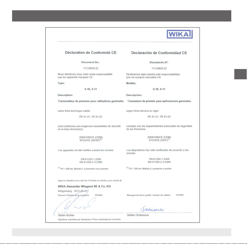
Annexe 1: Déclaration de conformité CE type S-11
F
14043046.01 06/2012 GB/D/F/E
75WIKA Mode d‘emploi transmetteur de pression, type S-11
Page 76

F
76 WIKA Mode d'emploi transmetteur de pression, type S-11
14043046.01 06/2012 GB/D/F/E
Page 77

Contenido
Contenido
1. Información general 78
2. Seguridad 80
3. Datos técnicos 83
4. Diseño y función 89
5. Transporte, embalaje y almacenamiento 89
6. Puesta en servicio, funcionamiento 90
7. Ajuste de punto cero y span 95
8. Mantenimiento y limpieza 96
9. Fallos 97
10. Desmontaje, devolución y eliminación 98
11. Accesorios 99
12. Anexo 1: Declaración CE de conformidad modelo S-11 75
Las declaraciones de conformidad encuentra en nuestra página web www.wika.es
14043046.01 06/2012 GB/D/F/E
E
77WIKA manual de instrucciones transmisores de presión, modelo S-11
Page 78

1. Información general
1. Información general
■
El transmisor de presión descrito en el manual de instrucciones está construido y fabricado según
los conocimientos actuales. Todos los componentes están sujetos a rigurosos criterios de calidad
y medio ambiente durante la producción. Nuestros sistemas de gestión están certicados según
ISO 9001 e ISO 14001.
■
Este manual de instrucciones proporciona indicaciones importantes acerca del manejo del instrumento. Para que el trabajo con este instrumento sea seguro es imprescindible cumplir con todas las
instrucciones de seguridad y manejo indicadas.
E
■
Cumplir siempre las normativas sobre la prevención de accidentes y las normas de seguridad en
vigor en el lugar de utilización del instrumento.
■
El manual de instrucciones es una parte integrante del instrumento y debe guardarse en la proximidad del mismo para que el personal especializado pueda consultarlo en cualquier momento.
■
El personal especializado debe haber leído y entendido el manual de instrucciones antes de comenzar cualquier trabajo.
■
El fabricante queda exento de cualquier responsabilidad en caso de daños causados por un uso no
conforme a la nalidad prevista, la inobservancia del presente manual de instrucciones, un manejo
por personal insucientemente cualicado así como una modicación no autorizada del instrumento.
■
Se aplican las condiciones generales de venta incluidas en la documentación de venta.
■
Modicaciones técnicas reservadas.
■
Para obtener más informaciones consultar:
- Página web: www.wika.es
- Hoja técnica correspondiente: PE 81.02
- Servicio técnico:
Tel.: (+49) 9372/132-8976
Fax: (+49) 9372/132-8008976
E-Mail: info@wika.es
78 WIKA manual de instrucciones transmisores de presión, modelo S-11
14043046.01 06/2012 GB/D/F/E
Page 79
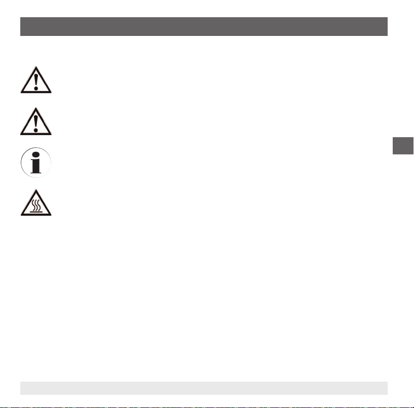
1. Información general
Explicación de símbolos
¡ADVERTENCIA!
… indica una situación probablemente peligrosa que puede causar la muerte o lesiones
graves si no se la evita.
¡CUIDADO!
... indica una situación probablemente peligrosa que puede causar lesiones leves o
medianas, o daños materiales y medioambientales, si no se la evita.
Información
... marca consejos y recomendaciones útiles así como informaciones para una utilización
ecaz y libre de fallos.
¡CUIDADO!
... indica una situación probablemente peligrosa que pueda causar quemaduras debido a
supercies o líquidos calientes si no se evita.
Abreviaturas
2 hilos Los dos líneas de conexión se utilizan para la alimentación de corriente.
La alimentación se realiza a través de la señal de medición.
3 hilos Se utilizan dos líneas de conexión para la alimentación de corriente.
Una línea de conexión es utilizada para la señal de medición.
U
+
U
-
S
+
Alimentación positiva
Potencial de referencia
Salida analógica
E
14043046.01 06/2012 GB/D/F/E
79WIKA manual de instrucciones transmisores de presión, modelo S-11
Page 80

2. Seguridad
2. Seguridad
¡ADVERTENCIA!
Antes del montaje, la puesta servicio y el funcionamiento asegurarse de que se haya
seleccionado el transmisor de presión adecuado con respecto a rango de medida, versión
y condiciones de medición especícas.
La inobservancia puede causar lesiones graves y/o daños materiales.
¡ADVERTENCIA!
■
E
2.1 Uso conforme a lo previsto
El transmisor de presión sirve para convertir la presión en una señal eléctrica en interiores y exteriores.
El instrumento ha sido diseñado y construido únicamente para la nalidad aquí descrita y debe
utilizarse en conformidad a la misma.
Cumplir las especicaciones técnicas de este manual de instrucciones. Un manejo no apropiado o una
utilización del transmisor de presión no conforme a las especicaciones técnicas requiere la inmediata
puesta fuera de servicio y la comprobación por parte de un técnico autorizado por WIKA.
No se admite ninguna reclamación debido a un manejo no adecuado.
Abrir las conexiones sólo cuando no estén sometidas a presión.
■
Tener en cuenta los parámetros de servicio según el capítulo 3 "Datos técnicos".
■
Operar el transmisor de presión únicamente dentro de los límites de presión admisibles!
Los distintos capítulos de este manual de instrucciones contienen otras importantes
indicaciones de seguridad.
80 WIKA manual de instrucciones transmisores de presión, modelo S-11
14043046.01 06/2012 GB/D/F/E
Page 81

2. Seguridad
2.2 Cualicación del personal
¡ADVERTENCIA!
¡Riesgo de lesiones debido a una insuciente cualicación!
Un manejo no adecuado puede causar considerables daños personales y materiales.
Las actividades descritas en este manual de instrucciones deben realizarse únicamente
por personal especializado con la cualicación correspondiente.
Personal especializado
Debido a su formación profesional, a sus conocimientos de la técnica de regulación y medición así
como a su experiencia y su conocimiento de las normativas, normas y directivas vigentes en el país de
utilización el personal especializado es capaz de ejecutar los trabajos descritos y reconocer posibles
peligros por sí solo.
Algunas condiciones de uso especícas requieren conocimientos adicionales, p. ej. acerca de medios
agresivos.
2.3 Riesgos especícos
¡ADVERTENCIA!
En el caso de sustancias peligrosas a medir, como p. ej. oxígeno, acetileno, sustancias
inamables o tóxicas, así como en instalaciones de refrigeración, compresores, etc.,
deben observarse en cada caso, además de todas las reglas generales, las disposiciones
pertinentes.
¡ADVERTENCIA!
Medios residuales en los transmisores de presión desmontado pueden causar riesgos para
personas, medio ambiente e instalación. Tomar adecuadas medidas de precaución.
No utilizar este instrumento en sistemas de seguridad o dispositivos de parada de
emergencia. Una utilización incorrecta del instrumento puede causar lesiones.
En caso de fallo es posible que haya medios agresivos con temperaturas extremas o de
bajo presión o que haya un vacío en el instrumento.
14043046.01 06/2012 GB/D/F/E
E
81WIKA manual de instrucciones transmisores de presión, modelo S-11
Page 82

2. Seguridad
2.4 Rótulos / Marcados de seguridad
Placa indicadora de modelo
Homologaciones
Rango de medida
Señal de salida
E
Alimentación auxiliar
S# nº de serie
P# nº de artículo
Detalles del
conexionado
Código 2D
Si el número de serie o el código 2D quedan ilegibles por daños mecánicos o pintura, ya no se puede
mantener la trazabilidad.
Explicación de símbolos
CSA, Canadian Standard Association
®
Este instrumento ha sido comprobado y certicado por CSA International. Los instrumentos con este marcaje están conformes a las normas aplicables de Canadá relativas a la
seguridad.
GOST, Gossudarstwenny Standart (Государственный Стандарт)
GOST-R (mark)
Los instrumentos con este marcaje cumplen las normativas aplicables en materia de
seguridad de Rusia (federación rusa).
CE, Communauté Européenne
Los instrumentos con este marcaje cumplen las directivas europeas aplicables.
82 WIKA manual de instrucciones transmisores de presión, modelo S-11
14043046.01 06/2012 GB/D/F/E
Page 83

3. Datos técnicos
3. Datos técnicos
3.1 Rangos de medida
Presión relativa (bar)
Rango de medida 0 ... 0,1 0 ... 0,16 0 ... 0,25 0 ... 0,4 0 ... 0,6 0 ... 1 0 ... 1,6
Límite de presión de sobrecarga
Presión de estallido 2 2 2,4 2,4 4,8 6 12
Rango de medida 0 ... 2,5 0 ... 4 0 ... 6 0 ... 10 0 ... 16 0 ... 25 0 ... 40
Límite de presión de sobrecarga
Presión de estallido 12 20,5 42 42 96 96 400
Rango de medida 0 ... 60 0 ... 100 0 ... 160 0 ... 250 0 ... 400 0 ... 600
Límite de presión de sobrecarga
Presión de estallido 550 600 600 600 1.600 1.600
Presión absoluta (bar)
Rango de medida 0 ... 0,25 0 ... 0,4 0 ... 0,6 0 ... 1 0 ... 1,6 0 ... 2,5 0 ... 4
Límite de presión de sobrecarga
Presión de estallido 2,4 2,4 4,8 6 12 12 20,5
Rango de medida 0 ... 6 0 ... 10 0 ... 16
Límite de presión de sobrecarga
Presión de estallido 42 42 96
Rango de medida de vacío y +/- (bar)
Rango de medida -0,1 ... 0 -0,16 ... 0 -0,25 ... 0 -0,4 ... 0 -0,6 ... 0 -1 ... 0 -1 ... +0,6
Límite de presión de sobrecarga
Presión de estallido 2 2 2,4 2,4 4,8 6 12
Rango de medida -1 ... +1,5 -1 ... +3 -1 ... +5 -1 ... +9 -1 ... +15 -1 ... +24
Límite de presión de sobrecarga 10 17 35 35 80 50
Presión de estallido 12 20,5 42 42 96 96
1 1,5 2 2 4 5 10
10 17 35 35 80 50 80
120 200 320 500 800 1.200
2 2 4 5 10 10 17
35 35 80
1 1,5 2 2 4 5 10
E
14043046.01 06/2012 GB/D/F/E
83WIKA manual de instrucciones transmisores de presión, modelo S-11
Page 84

3. Datos técnicos
Resistencia al vacío
Sí
3.3 Señales de salida
Tipo de señal Señal
Corriente (2 hilos) 4 ... 20 mA
Corriente (3 hilos) 0 ... 20 mA
Tensión (3 hilos) DC 0 ... 10 V
E
Dependiendo del tipo de señal valen las cargas siguientes:
Tipo de señal Carga en Ω
Corriente (2 hilos) ≤ (alimentación auxiliar - 10 V) / 0,02 A
Corriente (3 hilos) ≤ (alimentación auxiliar - 3 V) / 0,02 A
Tensión (3 hilos) > Señal de salida max. / 1mA
3.3 Alimentación de corriente
Alimentación auxiliar
La alimentación auxiliar permitida depende del correspondiente el señal de salida.
Señal de salida Alimentación auxiliar
4 ... 20 mA (2 hilos) DC 10 ...30 V
0 ... 20 mA (3 hilos) DC 10 ...30 V
DC 0 ... 10 V DC 14 ... 30 V
DC 0 ... 5 V DC 10 ...30 V
DC 0 ... 5 V
84 WIKA manual de instrucciones transmisores de presión, modelo S-11
14043046.01 06/2012 GB/D/F/E
Page 85

3. Datos técnicos
3.4 Precisión
Precisión con temperatura ambiente
■
Estándar: ≤ ±0,5 % del span
■
Opción: ≤ ± 0,25 % del span
1) Solo para rangos ≥ 0,25 bar
Incluye alinealidad, histéresis, error punto cero y valor nal (corresponde a desviación de valor de
medida según IEC 61298-2). Calibrado en posición vertical con la conexión a presión hacia abajo.
Alinealidad (según IEC 61298-2)
≤ ± 0,2 % del span BFSL
No repetibilidad
≤ ±0,1 % del span
Error de temperatura en el rango de temperatura nominal
Rango de temperatura nominal: 0 ... 80 °C
Coeciente de temperatura medio del punto cero
■
≤ 0,2 % del alcance/10 K
■
< 0,4 % del span/10 K
1) Rige para rangos de medición ≤ 0,25 bar
1)
Coeciente de temperatura medio del span
■
≤ 0,2 % del alcance/10 K
1)
E
Tiempo de establecimiento
≤ 10 ms
Deriva a largo plazo
≤ ±0,2 % del span/año
14043046.01 06/2012 GB/D/F/E
85WIKA manual de instrucciones transmisores de presión, modelo S-11
Page 86

3. Datos técnicos
Ajustabilidad punto cero y span
1)
El ajuste se realiza a través del potenciómetro del instrumento.
■
Punto cero: ±5 %
■
Span ±5 %
1) No es posible el ajuste en la salida del cable con tipo de protección IP 68
3.5 Condiciones de utilización
E
Clases de protección (nach IEC 60529)
La protección depende del modelo de la conexión eléctrica.
Conexión eléctrica Tipo de protección
Conector angular DIN 175301-803 A IP 65
Conector eléctrico, M12 x 1 (de 4 polos) IP 67
Salida de cable
■
Estándar IP 67
■
Opción IP 68
1) Ajustabilidad: punto cero y span imposible
1)
El tipo de protección indicado sólo es válido en estado conectado con conectores según el modo de
protección correspondiente.
Resistencia a la vibración
■
Conexiones sin torre de refrigeración
20 g (IEC 60068-2-6, con resonancia)
■
Conexiones con torre de refrigeración
10 g (IEC 60068-2-6, con resonancia)
86 WIKA manual de instrucciones transmisores de presión, modelo S-11
14043046.01 06/2012 GB/D/F/E
Page 87

3. Datos técnicos
Resistencia a choques térmicos
■
Conexiones sin torre de refrigeración
1.000 g (IEC 60068-2-27, mecánica)
■
Conexiones con torre de refrigeración
400 g (IEC 60068-2-27, mecánica)
Rangos de temperatura admisibles
Conexiones sin torre de refrigeración
Ambiente -20 ... +80 °C
Almacenamiento -40 ... +100 °C
1)
Medio
■
Estándar -30 ... +100 °C
■
Opción -30 ... +125 °C
1) Para rangos de medida 0 ... 400 y 0 ... 600 bar, es la temperatura del medio a -30 ... +70 ° C limitada.
2) En posición de montaje vertical el punto de medición tiene que aislarse para evitar lso efectos de la radiación térmica y de la
convección.
3.6 Conexiones eléctricas
Resistencia contra cortocircuitos
S+ contra U
-
Protección contra polaridad inversa
U+ contra U
-
Protección contra sobretensiones
DC 36 V
Conexiones con torre de refrigeración
Ambiente -20 ... +80 °C
Almacenamiento -40 ... +100 °C
Medio
1) 2)
-20 ... +150 °C
E
Tensión de aislamiento
DC 500 V bei NEC Class 02 Spannungsversorgung (Niederspannung und Niederstrom max. 100 VA
auch im Fehlerzustand)
14043046.01 06/2012 GB/D/F/E
87WIKA manual de instrucciones transmisores de presión, modelo S-11
Page 88

3. Datos técnicos
3.7 Conexiones
Conexión a proceso Rangos de medida
G ½ B membrana aorante
G 1 B, membrana aorante
Hygienic G 1 B membrana aorante 0 ... 0,1 a 0 ... 25 bar
3.8 Materiales
E
Piezas en contacto con el medio
Acero inoxidable
Los materiales de sellado véase tabla
Conexión a proceso Estándar Opción
sin torre de refrigeración NBR
con torre de refrigeración FPM/FKM EPDM
Hygienic EPDM -
Piezas sin contacto con el medio
Líquido interno de transmisión de presión
■
Estándar: Aceite sintético:
■
Opción: Líquido transmisor de presión apta para procesos alimentarios según
FDA 21 CFR 178.3750
1)
1)
0 ... 2,5 a 0 ... 600 bar
0 ... 0,1 a 0 ... 1,6 bar
■
FPM/FKM
■
EPDM
3.9 Homologaciones, directivas y certicados
Certicación
■
CSA
■
GOST
88 WIKA manual de instrucciones transmisores de presión, modelo S-11
14043046.01 06/2012 GB/D/F/E
Page 89

3. Datos técnicos / ... / 5. Transporte, embalaje y...
Conformidad CE
■
Directiva de EMC 2004/108/CE, EN 61326 emisión (grupo 1, clase B) y resistencia a interferencias
(ámbito industrial)
■
Directiva de equipos a presión 97/23/CE
Observar las especicaciones en el albarán para números de tipos especiales, p. ej. S-11000.
Para más datos técnicos véase la hoja técnica de WIKA PE 81.02 y la documentación de pedido.
4. Diseño y función
4.1 Descripción
La presión actual se mide a través de la deformación de la membrana en el elemento sensor. Mediante
la alimentación auxiliar, esta deformación de la membrana se transforma en una señal eléctrica. . La
señal de salida del transmisor de presión está amplicada y estandarizada. La señal de salida es proporcional a la presión medida.
4.2 Volumen de suministro
Comparar mediante el albarán si se han entregado todas las piezas.
5. Transporte, embalaje y almacenamiento
5.1 Transporte
Comprobar si el transmisor de presión presenta eventuales daños causados en el transporte.
Noticar daños obvios de forma inmediata.
5.2 Embalaje
No quitar el embalaje hasta justo antes del montaje.
Guardar el embalaje ya que es la protección ideal durante el transporte (por ejemplo si el lugar de instalación cambia o si se envía el instrumento para posibles reparaciones).
14043046.01 06/2012 GB/D/F/E
E
89WIKA manual de instrucciones transmisores de presión, modelo S-11
Page 90
5. Transporte, embalaje ... / 6. Puesta en servicio, funcionamiento
5.3 Almacenamiento
Condiciones admisibles en el lugar de almacenamiento:
■
Temperatura de almacenamiento: véase capítulo 3 "Datos técnicos"
■
Humedad: 45... 75 % humedad relativa ambiente
Evitar lo siguiente:
■
Vibración mecánica, impacto mecánico (colocación brusca)
■
Hollín, vapor, polvo y gases corrosivos
■
Entorno potencialmente explosivo, atmósferas inamables
E
Almacenar el transmisores de presión en su embalaje original en un lugar que cumple las condiciones
arriba mencionadas. Si no se dispone del embalaje original, empaquetar y almacenar el dispositivo
como sigue:
1. Aplicar el tapón protector en la conexión al proceso
2. Colocar el instrumento junto con el material aislante en el embalaje.
¡ADVERTENCIA!
Antes de almacenar el instrumento (después del funcionamiento), eliminar todos los restos
de medios adherentes. Esto es especialmente importante cuando el medio es nocivo para la
salud, como p. ej. cáustico, tóxico, cancerígeno, radioactivo, etc.
6. Puesta en servicio, funcionamiento
¡CUIDADO!
Comprobar el transmisor de presión visualmente antes de utilizarlo.
■
Si el líquido se derrama es probable que la membrana esté dañada.
■
Comprobar si la membrana de la conexión al proceso presenta daños.
■
Utilizar el transmisor de presión sólo en condiciones absolutamente seguras.
90 WIKA manual de instrucciones transmisores de presión, modelo S-11
14043046.01 06/2012 GB/D/F/E
Page 91

6. Puesta en servicio, funcionamiento
6.1 Montaje mecánico
■
Retirar la tapa protectora tan solo poco antes del montaje.
■
Asegurar que la membrana de la conexión al proceso no sufra daños
durante el montaje.
■
Las supercies de obturación en los transmisores de presión y en el
punto de medición deben estar siempre libres de suciedad.
■
Atornillar y desatornillar el instrumento únicamente aplicando la llave
en las supercies previstas para ello. Nunca utilizar la caja o el torre
de refrigeración como supercie de manipulación.
■
El par de giro correcto depende de la dimensión de la conexión así
como de la junta utilizada (forma/material).
■
No bloquear las vueltas de la rosca al enroscar.
■
Las indicaciones sobre taladros para roscar y para soldar se detallan
en nuestra información técnica IN 00.14 en www.wika.es.
■
Enchufar el conector y atornillarlo a mano. El montaje del conector angular se describe en el capítulo
6.2 "Montaje eléctrico".
Sellado
Para el sellado de las conexiones al proceso con roscas
Rosca cilíndrica Rosca cónica
según EN 837 según DIN 3852-E
rectas en la supercie de
obturación
se deben instalar
juntas planas, arandelas o
juntas perladas WIKA. Para
roscas cónicas (por ejemplo,
roscas NPT) se realiza el cierre
en la rosca con material de cierre complementario, como por ejemplo, cinta PTFE (EN 837-2).
Supercie plana
de ajuste
NPT, R y PT
E
Para notas acerca de las juntas, véase la hoja técnica WIKA AC 09.08 o www.wika.es.
14043046.01 06/2012 GB/D/F/E
91WIKA manual de instrucciones transmisores de presión, modelo S-11
Page 92

6. Puesta en servicio, funcionamiento
Dimensiones de las conexiones en mm
E
G D1 L1 L2 L3 L4
G ½ B 18 23 20,5 10 15,5
G D1 L1 L2 L3 L4
G 1 B Hygienic 29,5 28 25 9 15,5
92 WIKA manual de instrucciones transmisores de presión, modelo S-11
G D1 L1 L2 L3 L4
G 1 B 30 23 20,5 10 15,5
Las indicaciones sobre taladros para roscar y
para soldar están en nuestra información técnica
IN 00.14 en www.wika.es.
14043046.01 06/2012 GB/D/F/E
Page 93
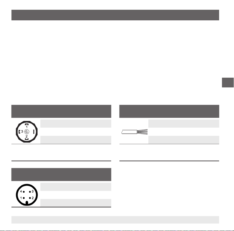
6. Puesta en servicio, funcionamiento
6.2 Montaje eléctrico
■
Poner a tierra el instrumento a través de la conexión.
■
Utilizar los instrumentos con salida de tensión con un cable blindado y poner a tierra el blindaje
en un lado del cable como mínimo si los cables tienen una longitud superior a 30 m o si salen del
edicio.
■
En América del Norte, conectar el instrumento a "Class 2 Circuits" o "Class 2 Power Units" según
CEC (Canadian Electrical Code) o NEC (National Electrical Code).
■
Seleccionar el correcto diámetro de cable para la entrada de cable del conector. Prestar atención
a que el prensaestopas del conector montado esté correctamente jado y que las juntas estén
presentes y no dañadas. Apretar el prensaestopas y comprobar si las juntas están jadas bien para
garantizar el tipo de protección.
■
Asegurarse de que no penetre humedad en las salidas en el extremo del cable.
Esquemas de conexiones
Conector angular DIN 175301-803 A
2 hilos 3 hilos
U+1 1
U-2 2
- 3
S
+
Sección de hilo max. 1,5 mm
Diámetro de cable 6 ... 8 mm
2
Conector eléctrico, M12 x 1 (de 4 polos)
2 hilos 3 hilos
U+1 1
U-3 3
- 4
S
+
Salida de cable, sin blindar
2 hilos 3 hilos
U+marrón marrón
U-verde verde
- blanco
S
+
Sección de hilo 3 x 0,5 mm
Diámetro de cable, 6,8 mm
Longitudes de cable 1,5 m, 3 m, 5 m, 10 m, 15 m
2
E
14043046.01 06/2012 GB/D/F/E
93WIKA manual de instrucciones transmisores de presión, modelo S-11
Page 94
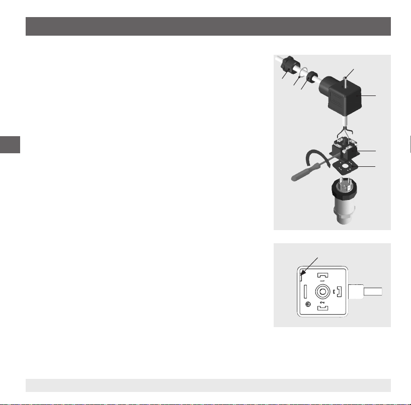
6. Puesta en servicio, funcionamiento
Montaje de la conector de salida lateral DIN 175301-803
1. Soltar el tornillo
2. Soltar el prensaestopas
3. Sacar el conector angular + del instrumento.
4. Quitar el bloque de terminales del conector angular
sacándolo de la ranura de montaje .
5. Pasar el cable con el diámetro exterior correspondiente (véase
"Esquema de conexiones") a través del prensaestopas , el
E
anillo , la junta y la caja .
6. Conectar los extremos asignación de cable en forma
correspondiente en los bornes de conexión del bloque de
terminales (Asignación véase el cuadro "Esquemas de
conexiones"
7. Apretar el conector angular en la caja .
8. Cerrar el prensaestopas . Asegurarse de que las juntas
no estén dañadas y que el prensaestopas y las juntas estén
montados correctamente para garantizar el tipo de protección.
9. Poner la junta plana cuadrada por encima de los conectores
del transmisor de presión.
10. Deslizar el conector angular montado + sobre los
conectores del transmisor de presión.
11. Usando el tornillo , atornillar a mano el conector angular al
transmisor de presión.
Ranura de montaje
94 WIKA manual de instrucciones transmisores de presión, modelo S-11
14043046.01 06/2012 GB/D/F/E
Page 95
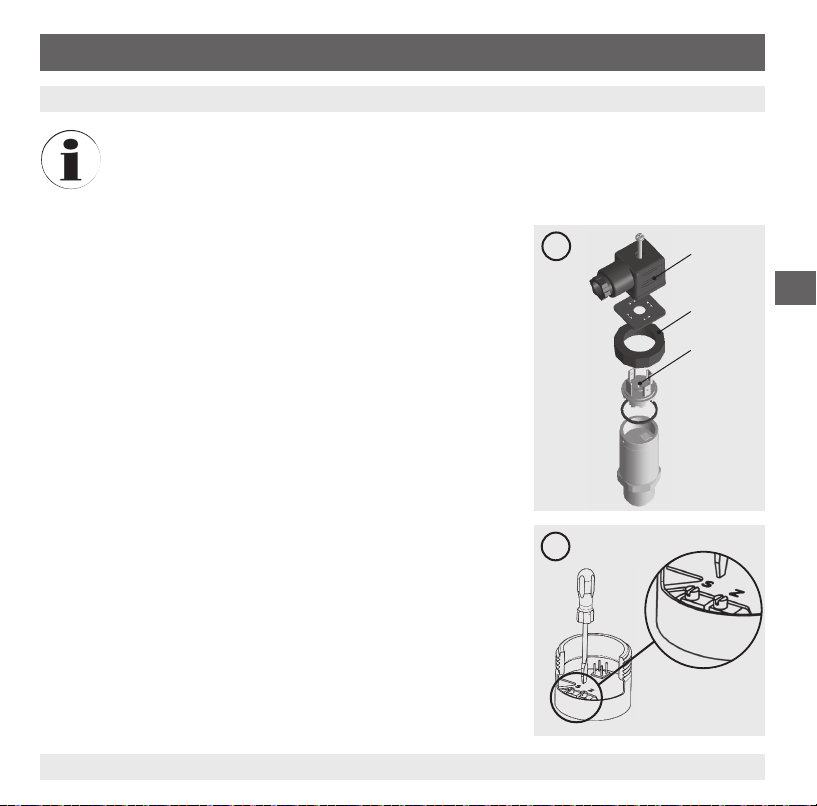
7. Ajuste de punto cero y span
7. Ajuste de punto cero y span
Solo utilizar el potenciómetro para ajustar el span si se dispone de un equipo de calibración
con una precisión mejor que el triple de la precisión del transmisor de presión.
7.1 Preparación (Illustración A)
Para acceder a los potenciómetros, abrir el instrumento como sigue:
■
Desconectar la conexión eléctrica del instrumento
■
Soltar el anillo roscado.
■
Retire con cuidado el conector desde el instrumento
■
Conectar el conector a la alimentación auxiliar y a una unidad
indicadora (p. ej. un amperímetro, un voltímetro) según el esquema de conexión.
7.2 Ajuste de punto cero (ílustración B)
■
Alcanzar el valor inicial del rango de medida
■
Ajustar mediante el potenciómetro "Z" la señal mínima de salida
(p. ej. 4 mA).
7.3 Ajuste span (ilustración B)
■
Alcanzar el valor nal del rango de medida
■
Acerca de los potenciómetro "S" ajustar la potencia máxima (p.
ej. 20 mA)
■
Comprobar el punto cero y volver a ajustar en caso de desviación.
■
Repetir el proceso hasta que el punto cero y el span estén correctamente ajustados.
A
E
B
14043046.01 06/2012 GB/D/F/E
95WIKA manual de instrucciones transmisores de presión, modelo S-11
Page 96

7. Ajuste de punto cero y span / 8. Mantenimiento y limpieza
7.4 Finalizar el ajuste (Abbildung A)
■
Desconectar el conector de la alimentación auxiliar y unidad indicadora.
■
Cuidadosamente, introducir el conector en el instrumento sin dañar los hilos conductores ni las
juntas. Las juntas tienen que estar limpias y sin daños para asegurar el tipo de protección indicado.
■
Apretar el anillo de empuñadura
Tras el ajuste comprobar si el sistema trabaja correctamente.
Ciclo de recalibración recomendado: 1 año
E
8. Mantenimiento y limpieza
8.1 Mantenimiento
El transmisor de presión no precisa mantenimiento.
Todas las reparaciones las debe efectuar únicamente el fabricante.
8.2 Limpieza
¡CUIDADO!
■
Antes de proceder con la limpieza hay que separar debidamente el instrumento de
cualquier fuente de presión, apagarlo y desenchufarlo de la alimentación auxiliar.
■
No utilizar ningún objeto puntiagudo o duro para efectuar la limpieza, para evitar
cualquier daño de la membrana de la conexión al proceso.
■
Limpiar el instrumento con un trapo húmedo.
■
Asegurarse de que las conexiones eléctricas no se humedecen.
■
Una vez desmontado el instrumento se debe enjuagar y limpiar antes de devolverlo para
proteger a las personas y el medio ambiente contra medios residuales de medición.
■
Medios residuales en el transmisores de presión desmontado pueden causar
riesgos para personas, medio ambiente e instalación. Tomar adecuadas medidas de
precaución.
Véase el capítulo 10.2 "Devolución" para obtener más información acerca de la devolución
del instrumento.
96 WIKA manual de instrucciones transmisores de presión, modelo S-11
14043046.01 06/2012 GB/D/F/E
Page 97

9. Fallos
9. Fallos
En caso de averías, comprobar en primer lugar la conexión mecánica y eléctrica.
Fallo Posible causa Medida
Ninguna señal de salida Cable roto
Energía auxiliar errónea/ausente
Señal de salida ausente/errónea Fallo de cableado Corregir el cableado
La señal de salida no cambia
cuando cambia la presión
Alcance de señal demasiado
pequeño/cae
Span de señal oscilante/impreciso
Desviación de señal de punto cero
Sobrecarga mecánica por sobrepresión Sustituir el instrumento
Sobrecarga mecánica por sobrepresión
Daños en la membrana
Limpiar la junta/supercie dañada/
sucia, la junta no asienta correctamente,
vueltas de rosca torcidas
Fuentes de interferencias CEM en el
entorno, (p. ej. convertidor de frecuencia)
Temperaturas de uso excesivas / insu-
cientes
Instrumento no conectado a tierra
Presión del medio de proceso fuerte-
mente ciclante
Temperaturas de uso excesivas / insu-
cientes
Posición de montaje diferente
Límite de presión de sobrecarga
excedido
Comprobar el paso
Corregir la corriente auxiliar
Sustituir el instrumento
Sustituir el instrumento
Limpiar la junta/supercie, reemplazar la junta
Blindar el instrumento; blindaje del
cable; quitar la fuente de interferencias
Observar las temperaturas admisibles
Conectar a tierra el instrumento
Amortiguación; asesoramiento por
parte del fabricante
Observar las temperaturas admisibles
Corregir punto cero
Sustituir el instrumento
E
14043046.01 06/2012 GB/D/F/E
97WIKA manual de instrucciones transmisores de presión, modelo S-11
Page 98

9. Fallos / 10. Desmontaje, devolución y eliminación
¡CUIDADO!
Si no es posible corregir los defectos mediante las medidas detalladas arriba, se debe
poner el transmisores de presión inmediatamente fuera de servicio y prevenir una puesta
en servicio errónea. En tal caso se debe consultar el fabricante. Si desea devolver el
instrumento, observar las indicaciones en el capítulo 10.2 "Devolución".
10. Desmontaje, devolución y eliminación
E
10.1 Desmontaje
¡Desmontar los instrumentos sólo si no está sometidos a presión!
Durante el desmontaje, no dañar la membrana de la conexión al proceso. Tras el desmontaje y la
limpieza (véase capítulo 8.2 "Limpieza"), colocar la tapa protectora en el instrumento para proteger la
membrana.
98 WIKA manual de instrucciones transmisores de presión, modelo S-11
¡ADVERTENCIA!
Medios residuales en el transmisores de presión desmontado pueden causar riesgos para
personas, medio ambiente e instalación.
Tomar adecuadas medidas de precaución.
¡ADVERTENCIA!
¡Riesgo de quemaduras!
¡Dejar enfriar el instrumento lo suciente antes de desmontarlo!
Peligro debido a medios muy calientes que se escapan durante el desmontaje.
14043046.01 06/2012 GB/D/F/E
Page 99

10. Desmontaje, devolución y eliminación / 11. Accesorios
10.2 Devolución
¡ADVERTENCIA!
Es imprescindible observar lo siguiente para el envío del instrumento:
Todos los instrumentos enviados a WIKA deben estar libres de sustancias peligrosas
(ácidos, lejías, soluciones, etc.).
Utilizar el embalaje original o un embalaje adecuado para la devolución del instrumento.
Rellenar el formulario de devolución y adjuntarlo al instrumento.
El formulario de devolución está disponible en la sección 'Servicio' de internet: www.wika.es.
10.3 Eliminación de residuos
Una eliminación incorrecta puede provocar peligros para el medio ambiente.
Eliminar los componentes de los instrumentos y los materiales de embalaje conforme a los reglamentos
relativos al tratamiento de residuos y eliminación vigentes en el país de utilización.
11. Accesorios
Denominación N° de pedido
Racores soldados por G ½ B membrana aforante 1192299
Racores soldados por G 1 B membrana aforante 1192264
Racores soldados por G 1 B Hygienic membrana aforante 2166011
E
14043046.01 06/2012 GB/D/F/E
99WIKA manual de instrucciones transmisores de presión, modelo S-11
Page 100

WIKA global
WIKA subsidiaries worldwide can be found online at www.wika.com.
WIKA Niederlassungen weltweit nden Sie online unter www.wika.de.
La liste des liales WIKA dans le monde se trouve sur www.wika.fr.
Sucursales WIKA en todo el mundo puede encontrar en www.wika.es.
WIKA Alexander Wiegand SE & Co. KG
Alexander-Wiegand-Straße 30
63911 Klingenberg • Germany
Tel. (+49) 9372/132-0
Fax (+49) 9372/132-406
E-Mail info@wika.de
www.wika.de
100 WIKA operating instructions pressure transmitter, model S-11
14043046.01 06/2012 GB/D/F/E
 Loading...