

White Rodgers 7904 User Manual

WHITE-RODGERS
Operator: Save these instructions for future use!
FAILURE TO READ AND FOLLOW ALL INSTRUCTIONS CAREFULLY
BEFORE INSTALLING OR OPERATING THIS CONTROL COULD CAUSE
PERSONAL INJURY AND/OR PROPERTY DAMAGE.
Your new White-Rodgers 5-Day/2-Day Digital Thermostat uses
the technology of a solid-state microcomputer to provide precise
time/temperature control. This thermostat offers you the flexibility to design heating and cooling programs that fit your needs.
Features:
• Battery powered (3 “AA” Energizer® alkaline batteries
included).
• Separate 5-day (weekday) and 2-day (weekend) programming
• Simultaneous heat and cool program storage
• Preprogrammed temperature control
• Four separate time/temperature settings per 24-hour period
Model No. 7904
Programmable Electronic Digital Thermostat
INSTALLATION AND
OPERATION INSTRUCTIONS
DESCRIPTION
• LCD continuously displays set point, and alternately displays time and room temperature
• Temperature override until next program period
• Manual program override (HOLD temperature)
• User may select either 12- or 24-hour clock display
• °F/°C convertibility
• Temperature range 45° to 90°F
• Standard five terminals for single or two-transformer systems
• B and O terminals for single stage heat pumps or damper
operation
This thermostat is intended for use with a low voltage system; do
not use this thermostat with a line voltage system. If in doubt
about whether your wiring is millivolt, line, or low voltage, have
it inspected by a qualified heating and air conditioning contractor
or electrician.
Do not exceed the specification ratings.
All wiring must conform to local and national electrical codes and
ordinances.
This control is a precision instrument, and should be handled
carefully. Rough handling or distorting components could cause
the control to malfunction.
ELECTRICAL DATA
Electrical Rating:
8 to 30 VAC 50/60 Hz. or D.C.
0.05 to 1.5 Amps (Load per terminal)
1.5 Amps Maximum Total Load (All terminals combined)
THERMAL DATA
Setpoint Temperature Range:
45°F to 90°F (7°C to 32°C)
Operating Ambient Temperature Range:
32°F to 105°F
Operating Humidity Range:
0 to 90% RH (non-condensing)
Shipping Temperature Range:
-40°F to 150°F
PRECAUTIONS
CAUTION
!
To prevent electrical shock and/or equipment damage, disconnect electric power to system at main fuse
or circuit breaker box until installation is complete.
WARNING
!
Do not use on circuits exceeding specified voltage.
Higher voltage will damage control and could cause
shock or fire hazard.
Do not short out terminals on gas valve or primary
control to test. Short or incorrect wiring will damage
thermostat and could cause personal injury and/or
property damage.
SPECIFICATIONS
APPLICATIONS
For use with:
• Standard heat/cool or heat only systems
• Electric heat systems
• Gas or oil fired systems
• Gas systems with intermittent ignition devices (I.I.D.)
and/or vent dampers
• Hydronic (hot water or steam) systems
• Single-stage heat pump systems
• Millivolt systems
DO NOT USE WITH:
• Multi-stage systems
• Systems exceeding 30 VAC and 1.5 amps
• 3-wire zoned hydronic heating systems
WHITE-RODGERS DIVISION
EMERSON ELECTRIC CO.
9797 REAVIS ROAD
ST. LOUIS, MISSOURI 63123-5398
Printed in U.S.A.
PART NO. 37-5599B
Replaces 37-5599A
9731
INSTALLATION
REMOVE OLD THERMOSTAT
1. Shut off electricity at the main fuse box until installation is
complete. Ensure that electrical power is disconnected.
2. Remove the front cover of the old thermostat. With wires
still attached, remove wall plate from the wall. If the old
thermostat has a wall mounting plate, remove the thermostat
and the wall mounting plate as an assembly.
3. Identify each wire attached to the old thermostat using the
labels enclosed with the new thermostat.
4. Disconnect the wires from old thermostat one at a time. DO
NOT LET WIRES FALL BACK INTO THE WALL.
5. Install new thermostat using the following procedures.
ELECTRIC HEAT OR SINGLE-STAGE
HEAT PUMP SYSTEMS
Read entire paragraph before setting electric heat switch. If you
are unsure of your application, contact a qualified serviceperson.
If you have a single-stage heat pump system, OR your system
uses central electric heat, then you must move the switch on the
back of the thermostat base to the electric heat position (see fig
1). The electric heat position is to the left. Use a small screw-
driver or pencil to move the switch.
ELECTRIC GAS
Electric/Gas switch
Figure 1. Back of thermostat base
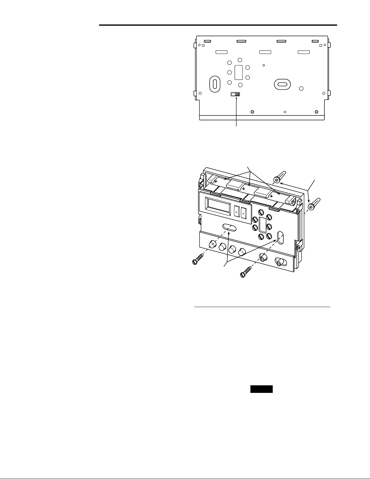
Alkaline batteries (3 “AA”–
install “+” ends to the left)
Screw anchors
ATTACH THERMOSTAT BASE TO WALL
1. Remove the packing material from the thermostat. Gently
pull the cover straight off the base. Forcing or prying on the
thermostat will cause damage to the unit. If necessary, move
the electric heat switch (see ELECTRIC HEAT SYSTEMS,
above).
2. Connect wires beneath terminal screws on base using
appropriate wiring schematic (see figs. 3 through 10).
3. Place base over hole in wall and mark mounting hole
locations on wall using base as a template.
4. Move base out of the way. Drill mounting holes.
5. Fasten base loosely to wall, as shown in fig. 2, using two
mounting screws. Place a level against bottom of base,
adjust until level, and then tighten screws. (Leveling is for
appearance only and will not affect thermostat operation.) If
you are using existing mounting holes, or if holes drilled are
too large and do not allow you to tighten base snugly, use
plastic screw anchors to secure subbase.
6. Push excess wire into wall and plug hole with a fire-resistant
material (such as fiberglass insulation) to prevent drafts from
affecting thermostat operation.
BATTERY LOCATION
This thermostat requires 3 “AA” alkaline batteries to operate. Batteries are included. Install the batteries along the top
of the base (see fig. 2). The batteries must be installed with the
positive (+) ends to the left.
If the word BATTERY is displayed, the batteries are low and
should be replaced with fresh “AA” Energizer® alkaline batteries.
RH
W
RC
G
Mounting
holes
B
O
Y
Figure 2. Thermostat base
HYDRONIC (HOT WATER OR STEAM)
HEATING SYSTEMS
This thermostat is set to operate properly if you have a forcedair heating system. If you have a hydronic heating system (a
system that heats with hot water or steam), you must set the
thermostat to operate properly with your system. To change the
setting, press and hold SET TIME and VIEW PRGM buttons at
the same time until the correct setting is displayed (A for forced
air; H for hydronic systems).
NOTE
If you do not press both buttons at the same time, A or H will not
be displayed. If this happens, press RUN PRGM, then press and
hold SET TIME and VIEW PRGM at the same time.
2
 Loading...