

White Rodgers 1F94W-71 User Manual
OPERATION GUIDE
7 Day Multi-stage/Heat Pump
Electronic Digital Thermostat
WHITE-RODGERS
Operator: Save this booklet for future use!
1F94W-71

About Your New Thermostat . . .
Your new Digital COMFORT SET II Multi-stage/Heat Pump Thermostat uses the technology of a
solid-state microcomputer to provide precise time/temperature control. The COMFORT SET II
Thermostat offers you the flexibility to design heating and cooling programs that fit your needs.
Please read this manual thoroughly before operating or programming your thermostat. If you have
questions, you may write to our Technical Service Department at the address shown on the back
cover of this booklet.
2

In This Guide . . .
YOUR NEW THERMOSTAT’S
FEATURES ........................................... 4
OPERATING YOUR THERMOSTAT ........ 5
PARTS OF THE THERMOSTAT
The Back Of the Thermostat Body
The Display
The Thermostat Buttons
OPERATING FEATURES
PROGRAMMING YOUR
THERMOSTAT ................................... 18
PLANNING FOR YOUR NEEDS
ENTERING YOUR PROGRAM
Set Current Time and Day
Program Heating and Cooling
Temperatures
Program Heating/Cooling Times
and Heating Temperatures
Program Cooling Temperatures
Using the HOLD/COPY Button
CHECK YOUR PROGRAMMING
QUESTIONS AND ANSWERS................ 33
Operator: Save this
booklet for future use!
3

YOUR NEW THERMOST A T’S FEA TURES
• Computed Energy Management Recovery
(EMR)
• Automatic changeover (operator-selectable)
• Separate setback programming for 7 independent days
• Simultaneous heat and cool program storage
• Four separate time/temperature settings per
24-hour period
• Armchair programming capability
• Up to 3 stages of heat and up to 2 stages of
cool
• Backlit LCD displays continuous set point,
time, and room temperature
• 9 volt Energizer® alkaline battery backup
• Preprogrammed temperature control
4
• Adjustable cycle times
• Compressor short cycle protection
• Compressor long term cycle protection
• Blower delay in the cooling cycle
• Audio and visual prompting during operation
• Two hour temperature override
• Manual program override (HOLD temperature)
• °F/°C convertibility
• Keypad lockout (operator-selectable)
• Temperature range 40° to 99°F
• Compatible with Remote Sensor (installerselectable)
OPERATING YOUR THERMOSTAT
Before you begin programming your thermostat, you should be familiar with its features and
with the display and the location and operation
of the thermostat buttons. The information in
this section will help you become familiar with
your new thermostat so that you can easily
program it.
Your thermostat consists of two parts: the ther-
mostat body and the subbase.
CAUTION
!
SYSTEM
Use
to turn thermostat OFF be-
HEAT/EMER/OFF/
COOL/AUTO
fore removing or attaching the thermostat body. Equipment damage and/or personal injury could occur.
The subbase is attached to the wall, but you can
remove the thermostat body for easy programming. To remove the thermostat body from the
subbase, grasp the thermostat body and gently
pull it out from the bottom of the subbase and
pivot up. To attach the thermostat body, line up
the four terminal pins on the upper section of the
thermostat back with the matching connector on
the subbase. Insert these, then gently pivot the
thermostat body down to connect the eight pin
connectors on the lower portion of the thermostat back. Gently push until the snap connectors
engage. DO NOT FORCE OR PRY THE THER-
MOSTAT as this may damage the unit.
5
PARTS OF THE THERMOSTAT
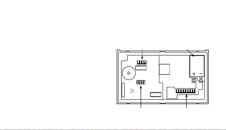
The Back of The Thermostat Body
Turn the thermostat body over. On the back are
the 9 volt Energizer® alkaline battery and the
option switches.
1. The 9 volt Energizer® alkaline battery provides power to the thermostat when the 24
VAC power is interrupted (for example, when
you remove the thermostat from the wall for
programming). A fresh battery will maintain
the stored program for approximately a week.
If power loss is long enough for the program
to be lost, the thermostat will automatically
return to the factory programmed temperatures (64°F heating and 82°F cooling) when
power is restored. You must reprogram the
thermostat if this happens.
6
If the word BATTERY is flashing in the
display window, the battery is low and should
be replaced with a fresh 9 volt Energizer®
alkaline battery. The battery will provide
power for all functions except the display
light, which works only on 24 VAC power.
4-pin connector
W18
Option switches 9-pin connector
BACK OF THERMOSTAT BODY
Battery
CAUTION
!
SYSTEM
Use
to turn thermostat OFF be-
HEAT/EMER/OFF/
COOL/AUTO
fore removing thermostat from the wall
to replace the battery.
2. You may adjust the option switches for
keypad lockout and automatic changeover
from heat to cool (see OPERATING FEA-
TURES).
Other than and , the buttons are located behind the thermostat door. To open the
door, use your fingernail in the indentation at the
top center of the door. Pull the door out, then
swing the door down on its hinges.
Following are brief descriptions of the display
and the thermostat buttons.
7

4
5
6
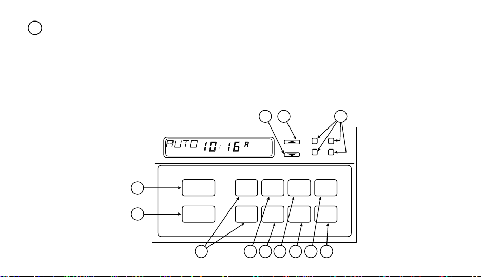
The Display
Continuously displays system mode (HEAT,
1
EMER, OFF, COOL, AUTO, HOLD). During programming, the day of the week is
displayed (MO, TU, WE, etc.).
When
the setpoint temperature displayed (at the
far right) is the 1st programmed heating or
cooling temperature (depending on mode).
B is displayed when the 2nd programmed
VIEW
is pressed, A is displayed when
TEMP
heating or cooling temperature is being dis-
Alternately displays room temperature (F
2
denotes degrees Fahrenheit and C denotes
degrees Celsius) and time of day (A denotes AM time and P denotes PM time).
played.
FAN ON is displayed when the blower is
operating continuously. FAN AUTO is displayed during automatic fan operation (when
Displays the setpoint temperature.
3
the blower cycles with the heating or cooling
system).
The word BATTERY flashes on the display
when the 9 volt alkaline battery power is
weak and should be replaced.
8

5 DAY FAN AUTO
SYSTEM
HEAT/EMER/OFF/
COOL/AUTO
FAN
ON-AUTO
TIME
FWD
TIME
BACK
SET
CLOCK
ADV
DAY
VIEW
PRGM
VIEW
TEMP
EMER. PUMP
AUX.MALF.
HOLD
COPY
RUN
PRGM
1 2 3
2 DAY
FAN AUTO FAN ONBAT
4
6
5 DAY
3
6
54
2
9

13
14
15
16
17
The Thermostat Buttons
Sets the system mode (HEATing, OFF,
7
COOLing, or AUTOmatic changeover).
Selects fan operation (see #5, above).
8
Runs display forward or backward through
9
time, day, or anticipation settings during
programming.
Used with
10
TIME
FWD
and
TIME
to set current time
BACK
and day of the week.
Used during programming to set the day of
11
the week to be programmed.
Used to initiate or review programming (pro-
12
gram viewing automatically begins with
Monday’s program; use
ADV
button to view
DAY
programming for following days).
10
Used with
TIME
FWD
and
TIME
to select setpoint
BACK
temperatures.
Used to manually override programming to
hold at a selected temperature (when HOLD
is displayed). Also used to copy one day’s
programming to another day (when COPY
is displayed).
Used to start program operation after programming. Also used to return thermostat to
program operation after being in HOLD
mode.
(Red arrow) Raises temperature setting
(99°F or 37°C maximum).
(Blue arrow) Lowers temperature setting
(40°F or 4°C minimum).
EMER light indicates that the system is in
18
the emergency mode (the heat pump compressor is off and the auxiliary heat system
is maintaining the setpoint temperature —
there is a 5- to 10-minute startup delay on
the first emergency cycle). MALF light indicates a heat pump system malfunction (re-
fer to heat pump manufacturer’s operating
manual). A continuous (non-flashing) PUMP
light indicates that the heat pump compressor is functioning — a flashing PUMP light
indicates that the compressor is locked out.
AUX light indicates that the auxiliary system
is operating.
16 17
18
VIEW
PRGM
VIEW
TEMP
EMER. PUMP
AUX.MALF.
HOLD
COPY
RUN
PRGM
5 DAY FAN
TIME
7
8
SYSTEM
HEAT/EMER/OFF/
COOL/AUTO
FAN
ON-AUTO
9
SET
FWD
CLOCK
TIME
ADV
BACK
DAY
10 11 12 13 14 15
11

OPERATING FEATURES
Now that you are familiar with the thermostat
display and buttons, read the following information to learn about the many features of the
thermostat.
• COMPUTED ENERGY MANAGEMENT
RECOVERY (EMR) — The thermostat’s
microcomputer automatically calculates the
time it will take to change the temperature to
the next program setting. Then the thermostat will activate the heating or cooling system to change the temperature so that the
desired temperature is reached at the beginning of the next program period. As an
example of this feature, assume that you
have programmed your thermostat to provide an overnight heating temperature of
62°F, and that during the next program
12
period, beginning at 6:00 AM, you have
programmed a temperature of 70°F. The
thermostat will automatically activate the
heating system at about 5:00 AM, so that
the programmed 70°F temperature is
reached by about 6:00 AM.
• AUTOMATIC CHANGEOVER — You can
set the thermostat to automatically switch
the system from heating to cooling as
needed. First you must move option switch
#4 (located on the back of the thermostat
body) to the ON position, if it has not already
been done. To do this, press
SYSTEM
HEAT/EMER/OFF/
COOL/AUTO
to turn
thermostat OFF. Then remove the thermostat body from the wall. Check the position
of switch #4 (the last switch on the right). If
it is ON (up), simply put the thermostat back
on the wall. If the switch is OFF (down),
remove the battery, then use a pencil or
 Loading...