

White Rodgers 1F92W-51 User Manual
INSTALLATION &
OPERATION GUIDE
Multi-stage/Heat Pump Electronic
Digital Thermostat
WHITE-RODGERS
Operator: Save this booklet for future use!
1F92W-51

About Your New Thermostat . . .
Your new White-Rodgers Digital Multi-stage/Heat Pump Thermostat uses the technology of a solid-state
microcomputer to provide precise time/temperature control. This thermostat offers you the flexibility to
design heating and cooling programs that fit your needs.
Please read this manual thoroughly before operating or programming your thermostat. If you have
questions, contact us at the address shown on the back cover of this manual.
2

In This Guide . . .
YOUR NEW THERMOSTAT’S
FEATURES .................................................. 4
PRECAUTIONS ................................................. 5
THE THERMOSTAT’S SPECIFICATIONS ....... 6
INSTALLING YOUR THERMOSTAT ................ 7
NEW INSTALLATION
Select Thermostat Location
Route Wires to Location
REPLACEMENT INSTALLATION
Remove Old Thermostat
Attach Subbase to Wall
SYSTEM CONFIGURATON
Set Option Switches
CHECK THERMOSTAT OPERATION
Fan Operation
Heating System Operation
Cooling System Operation
LOCKOUT BYPASS OPTION
Compressor Long Term Cycle Protection
Compressor Short Term Cycle Protection
OPERATING YOUR THERMOSTAT ............... 22
PARTS OF THE THERMOSTAT
The Back Of the Thermostat Body
The Display
The Thermostat Buttons
OPERATING FEATURES
PROGRAMMING YOUR
THERMOSTAT........................................... 34
PLANNING FOR YOUR NEEDS
ENTERING YOUR PROGRAM
Set Current Time and Day
Enter Heating Program
Enter Cooling Program
CHECK YOUR PROGRAMMING
QUESTIONS AND ANSWERS........................ 44
3

YOUR NEW THERMOSTAT’S FEATURES
• Five-day/two-day programming capability
• Simultaneous heat and cool program storage
• Four separate time and temperature settings
per 24-hour period
• Up to 2 stages of heat and up to 1 stage of cool
• Computed Energy Management Recovery
(EMR)
• Automatic changeover (operator selectable)
• Two hour temperature override
• Manual program override (HOLD temperature)
• “Advance Program” button
• Armchair programming capability
• LCD displays continuous setpoint, time, and
room temperature
4
• Adjustable cycle times
• 9 volt Energizer® alkaline battery backup
• Compressor long term cycle protection
• Compressor short cycle protection
• Blower delay in the cooling cycle
• Preprogrammed temperature control
• Visual prompting during operation
• Programmable blower control
• Temperature range 40° to 99°F
• °F/°C convertibility
• Electric Heat (installer-selectable)
PRECAUTIONS
If in doubt about whether your wiring is millivolt, line,
or low voltage, have it inspected by a qualified
heating and air conditioning contractor, electrician,
or someone familiar with basic electricity and wiring.
Do not exceed the specification ratings.
All wiring must conform to local and national electri-
cal codes and ordinances.
This control is a precision instrument, and should be
handled carefully. Rough handling or distorting components could cause the control to malfunction.
CAUTION
!
To prevent electrical shock and/or equipment damage, disconnect electric power to
system, at main fuse or circuit breaker box,
until installation is complete.
WARNING
!
Do not use on circuits exceeding specified
voltage. Higher voltage will damage control
and could cause shock or fire hazard.
Do not short out terminals on gas valve or
primary control to test. Short or incorrect
wiring will burn out thermostat and could
cause personal injury and/or property
damage.
5

THE THERMOSTAT’S SPECIFICATIONS
THIS CONTROL IS DESIGNED FOR USE WHERE BOTH SIDES OF THE TRANSFORMER ARE
PRESENT AT THE THERMOSTAT (both the hot and common sides of the 24 VAC end of the
transformer.)
ELECTRICAL DATA
Electrical Rating:
20 to 30 VAC 50/60 Hz.
0.01 to 1.5 Amps (Load per terminal)
2.5 Amps Maximum Total Load (All terminals
combined)
Anticipation:
Heating 4 to 40
Cooling 4 to 40
Auxiliary 4 to 40
STAGING DATA
Up to 3 heating stages
Up to 1 cooling stage
6
THERMAL DATA
Setpoint Temperature Range:
40°F to 99°F (4°C to 37°C)
Operating Ambient Temperature Range:
32°F to 105°F
Operating Humidity Range:
0 to 90% RH (non-condensing)
Shipping Temperature Range:
-40°F to 150°F
ACCESSORIES
Thermostat Guard:
W. R. Part No. F29-0198 (clear)
or F29-0238 (opaque)
INSTALLING YOUR THERMOSTAT
NEW INSTALLATION
WE RECOMMEND THAT YOU PROGRAM THE
THERMOSTAT WITH BATTERY INSTALLED BEFORE ATTACHING ON SUBBASE. SEE OPERATION SECTION FOR PROGRAMMING INSTRUCTIONS.
SELECT THERMOSTAT LOCATION
Proper location insures that the thermostat will
provide a comfortable building temperature. Observe the following general rules when selecting
a location:
1. Locate thermostat about 5 ft. above the floor.
2. Install thermostat on a partitioning wall, not on an
outside wall.
3. Never expose thermostat to direct light from
lamps, sun, fireplaces or any temperature radiating equipment.
4. Avoid locations close to windows, adjoining outside walls, or doors that lead outside.
5. Avoid locations close to air registers or in the
direct path of air from them.
6. Make sure there are no pipes or duct work in that
part of the wall chosen for the thermostat location.
7. Never locate thermostat in a room that normally
warmer or cooler than the rest of the building.
8. Avoid locations with poor air circulation, such as
behind doors or in alcoves.
ROUTE WIRES TO LOCATION
NOTE
All wiring must conform with local and national
electrical codes and ordinances.
7
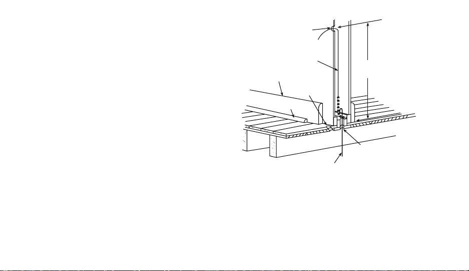
1. Probe for obstructions in partition before drilling
1
⁄2” hole in wall at selected location. Take up
quarter round and drill a small guide hole for
sighting (see fig. 1). From basement, drill 3⁄4” hole
in partition floor next to guide hole. In buildings
without basements, drill 1⁄2” hole through ceiling
and into partition from above (see fig. 1).
2. Through this hole drop a light chain, or 6” chain
attached to a strong cord. Snag cord in basement
with hooked wire. In buildings without basements, drop cord through hole in ceiling and
down partitioning; snag cord at the thermostat
location.
3. Attach thermostat wires to cord and pull wires
through hole in wall so that 6” of wire comes out
of the wall.
8
1
⁄2” hole for
thermostat wire
Stout cord with 6”
chain attached
Baseboard
strip moulding
Quarter round
removed
1
⁄4” guide hole
for sighting
Hooked wire for snagging chain
Approximately
5 feet from floor
3
⁄4” hole in floor of partition
Figure 1. Routing thermostat wires

REPLACEMENT INSTALLATION
TABLE 1. WIRE IDENTIFICATION LABELS
1
G
G
1
9
Y1
Y1
9
2
C
C
2
3
L
L
3
4
R
R
4
5
O
O
5
6
B
B
6
7
E1
E1
7
8
E2
E2
8
10
Y2
Y2
10
11
W1
W1
11
12
W2
W2
12
13
W3
W3
13
14
S1
S1
14
15
S2
S2
15
16
S3
S3
16
REMOVE OLD THERMOSTAT
1. Shut off electricity at the main fuse box until
installation is complete. Verify power is off
with a voltmeter.
2. Remove the front cover of the old thermostat. With wires still attached, remove
wall plate from the wall.
3. If the old thermostat has a wall mounting
plate, remove the thermostat and the wall
mounting plate as an assembly.
4. Use the Cross Reference Guide to find the
thermostat type you are replacing.
5. Identify each wire attached to the old thermo-
stat using the labels enclosed with the new
thermostat (see Table 1). Record the identification of the wire on the corresponding blank
in Table 2.
6. Disconnect the wires from old thermostat one at
a time. Pull at least 6 inches of wire out of the
wall. DO NOT LET WIRES FALL BACK INTO
THE WALL.
7. Install new thermostat using the following procedures.
9
LABEL
NUMBER
10
(1)
(2)
(3)
(4)
(5)
(6)
(7)
(8)
(9)
(10)
(11)
(12)
(13)
TABLE 2. TERMINAL REFERENCE
NEW THERMOSTAT
TERMINAL
DESIGNATION FUNCTION
G
C
L
R
O
B
E1
Fan Output
Transformer 24 VAC Common
(this terminal not used)
Transformer 24 VAC Hot
Changeover Output (Cooling)
Changeover Output (Heating)
Emergency Heat Relay (cycles on
1st stage in Emergency Mode)
E2
Emergency Heat Relay (continually
energized in Emergency Mode)
Y1
Y2
W1
W2
W3
Stage 1 Cool
(this terminal not used)
Stage 1 Heat (Compressor)
Stage 2 Heat (Auxiliary)
(this terminal not used)
OLD THERMOSTAT
TERMINAL
DESIGNATION

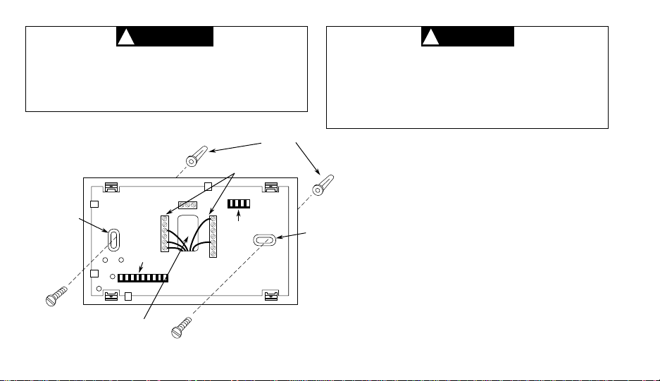
ATTACH SUBBASE TO WALL
1. Remove the packing material from the thermostat. Place the fingers of one hand on the center
top and bottom portion of the thermostat. Grasp
the subbase in the other hand on the top and
bottom center, and gently pull straight out (see
fig. 2). The thermostat has pin and socket connectors. Forcing or prying on the thermostat will
cause damage to the unit.
2. Connect wires beneath terminal screws on subbase using wiring schematic for your particular
application (see figs. 3 through 6).
3. Place subbase over hole in wall and mark
mounting hole locations on wall using subbase
as a template.
4. Move subbase out of the way. Drill mounting
holes.
5. Fasten subbase loosely to wall, as shown in fig.
3, using two mounting screws. Place a level
against bottom of subbase, adjust until level, and
then tighten screws. (Leveling is for appearance
only and will not affect thermostat operation.) If
you are using existing mounting holes, or if holes
drilled are too large and do not allow you to
tighten subbase snugly, use plastic expansion
plugs to secure subbase.
6. Push excess wire into wall and plug hole with a
fire-resistant material (such as fiberglass insulation) to prevent drafts from affecting thermostat
operation.
(Instructions continue on page 16).
11
CAUTION
!
WARNING
!
DO NOT EXCEED MAXIMUM VOLTAGE OR
CURRENT RATINGS. FIRE, PERSONAL INJURY, AND/OR EQUIPMENT DAMAGE
COULD RESULT.
Connect wires under
terminal screws
S3
S2
Mounting
hole
9-pin connector
Pull wires through
this opening
S1
O
W1
E1
B
Y1
Y2
C
G
4-pin connector
E2
L
R
W2
W3
Figure 3. Subbase
12
Expansion
plugs
To prevent electrical shock and/or equipment damage, disconnect electrical power
at the main fuse box until installation is
complete. Verify power is off with a voltmeter.
Mounting
hole
NOTE
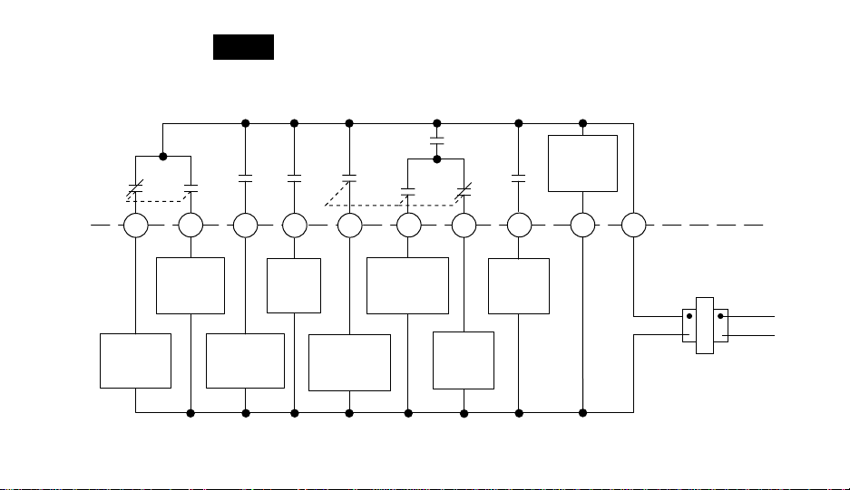
The following wiring diagrams show typical terminal identification and wiring. For proper installation, refer to the
original manufacturers' instructions.
Thermostat
Control
Circuit
O
Changeover
Energized
In Cool
B
Changeover
Energized
In Heat
G
Y1 W1
Fan
Relay
Compressor
Contactor
Stage 1
E2
Emergency
Relay
Constant
Output
E1
Emergency
Relay
Switched
Output
W2
Heat
Relay
Stage 2
Heat
Relay
Stage 1
C R
Figure 4. Typical wiring diagram for single transformer systems
THERMOSTAT
SYSTEM
Hot
24 VAC 120 VAC
Neutral
TRANSFORMER
13
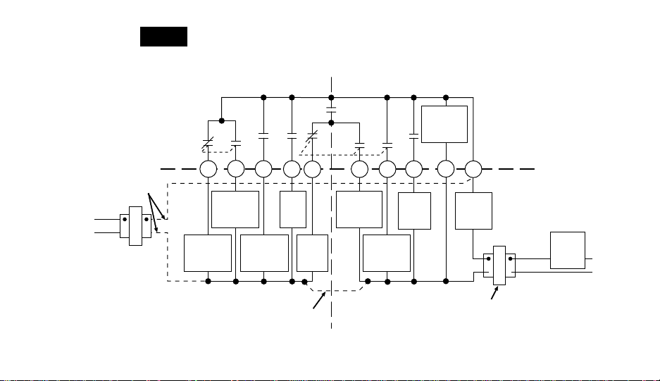
NOTE
IF SAFETY CIRCUITS ARE IN ONLY ONE OF THE
SYSTEMS, REMOVE THE TRANSFORMER OF THE
SYSTEM WITH NO SAFETY CIRCUITS.
Thermostat
Control
Circuit
14
CUT AND
TAPE OFF!
Hot
Neutral
TRANSFORMER
24 VAC120 VAC
B
O
Changeover
Changeover
Energized
In Cool
HEAT PUMP SYSTEM AUXILIARY HEATING SYSTEM
TWO COMMONS MUST
BE JUMPERED TOGETHER!
Energized
In Heat
Compressor
Y1
Contactor
Stage 1
G
Fan
Relay
W1
Heat
Relay
Stage 1
Emergency
Relay
Switched
Output
Emergency
E2
W2E1
Heat
Relay
Stage 2
Relay
Constant
Output
DEPENDING ON SYSTEM REQUIRE-
75VA TRANSFORMER, IF NEEDED
C
MENTS, REPLACE WITH A
R
Limit or
Safety
Switches
24 VAC
THERMOSTAT
SYSTEM
TRANSFORMER
Hot
120 VAC
Neutral
Limit or
Safety
Switches
Figure 5. Typical wiring diagram for two transformer systems with NO safety circuits
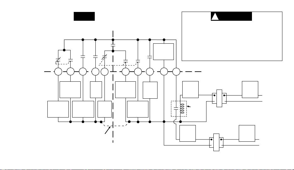
Relay contacts shown are thermostatically operated. The
CAUTION
!
NOTE
accessory relay scheme is required when safety circuits
exist in both systems.
Thermostat
Control
Circuit
Polarity must be observed. If the HOT
side of the second transformer is
jumpered to the COMMON side of the
first transformer a short will be made.
Damage to equipment will occur when
power is restored.
B
O
Changeover
Changeover
Energized
In Cool
HEAT PUMP SYSTEM AUXILIARY
TWO COMMONS MUST
BE JUMPERED TOGETHER!
Energized
In Heat
Compressor
Y1
Contactor
Stage 1
G
Fan
Relay
W1
Heat
Relay
Stage 1
Emergency
Relay
Switched
Output
E2
W2E1
Heat
Relay
Stage 2
Emergency
Relay
Constant
Output
HEATING SYSTEM
C
THERMOSTAT
R
SYSTEM
Limit or
Safety
Switches
Accessory
Relay N.O.
Limit or
Safety
Switches
24 VAC
24 VAC
Contact
24 VAC
AUXILIARY
HEATING
TRANSFORMER
HEAT PUMP
TRANSFORMER
Hot
Neutral
Hot
120 VAC
Neutral
120 VAC
Limit or
Safety
Switches
Limit or
Safety
Switches
Figure 6. Typical wiring diagram for two transformer systems with safety circuits in BOTH systems
15
ATTACH THERMOSTAT TO SUBBASE
WE RECOMMEND THAT YOU SET OPTION
SWITCHES TO DESIRED POSITION BEFORE ATTACHING ON SUBBASE (see OPERATION). WE
ALSO RECOMMEND THAT YOU PROGRAM THE
THERMOSTAT WITH BATTERY INSTALLED BEFORE ATTACHING ON SUBBASE (see OPERATION section for programming instructions).
SYSTEM
USE
HEAT-OFF-COOL-AUTO
TO TURN THERMOSTAT OFF BE-
FORE ATTACHING TO WALL. FAILURE TO TURN
OFF THERMOSTAT BEFORE ATTACHING TO
WALL MAY CAUSE EQUIPMENT DAMAGE DUE
TO RAPID COMPRESSOR CYCLING.
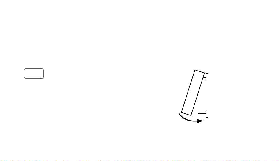
To attach thermostat to subbase, line up the plastic
snap guides at the top of the thermostat and the 4
connector pins on the thermostat with the connectors near the top right section of the subbase (when
viewed from the front). Gently pivot the thermostat
down until the 9-pin connectors and the plastic
16
snaps lock into place (see fig. 7). Be gentle when
attaching thermostat. If the thermostat does not
seem to be attaching to the subbase easily, make
sure that the connector pins and plastic snaps are
properly aligned, and that excess wire is pushed into
the wall. Damage to the thermostat may occur if
force is used.
ENGAGE TWO UPPER GUIDES; PIVOT DOWN
Figure 7. Attaching thermostat to subbase
 Loading...