


RF364PXPB3
Whirlpool RF364PXPB3, RF370LXPT3, RF380LXPB3, RF380LXPQ3, RF378LXPQ3 Installation Guide
...
INSTALLATIONINSTRUCTIONS
30" (76 CM) FREESTANDINGELECTRICRANGES
Table of Contents
RANGESAFETY..................................................................1
INSTALLATIONREQUIREMENTS.....................................2
Tools andParts ................................................................2
Location Requirements....................................................2
ElectricalRequirements...................................................3
INSTALLATION INSTRUCTIONS.......................................4
Unpack Range..................................................................4
InstallAnti-Tip Bracket.....................................................5
ElectricalConnection .......................................................6
VerifyAnti-Tip Bracket Location......................................9
LevelRange....................................................................10
Complete Installation......................................................10
Movingthe Range..........................................................10
ANTI-TIP BRACKETTEMPLATE ....................................12
RANGE SAFETY
Your safety and the safety of others are very important.
We have provided many important safety messages in this manual and on your appliance. Always read and obey all safety
messages.
This is the safety alert symbol.
This symbol alerts you to potential hazards that can kill or hurt you and others.
All safety messages will follow the safety alert symbol and either the word "DANGER" or "WARNING."
These words mean:
You can be killed or seriously injured if you don't immediately
follow instructions.
You can be killed or seriously injured if you don't follow
instructions.
All safety messages will tell you what the potential hazard is, tell you how to reduce the chance of injury, and tell you what can
happen if the instructions are not followed.
1.__ 1 Tip Over Hazard
A child or adult can tip the range and be killed.
Connect anti-tip bracket to rear range foot,
Reconnect the anti-tip bracket, if the range is moved.
Failure to follow these instructions can result in death or serious burns to children and adults.
iMPORTANT:
Save for local electrical inspector's use.
Installer: Leave installation instructions with the homeowner.
Homeowner: Keep installation instructions for future reference.
9758377
INSTALLATIONREQUIREMENTS
Gather the required tools and parts before starting installation.
Read and follow the safety instructions provided with any tools
listed here.
Tools needed
• Tape measure • %" drive rachet
• Flat-blade screwdriver • 1A"nut driver
• Level • %" and SA6"nut driver
• Hammer • 1/s"(3.2 mm) drill bit (for
• Hand or electric drill wood floors)
• Channel lock pliers • 3A6"(4.8 mm) carbide-tipped
masonry drill bit (for
• Marker or pencil concrete/ceramic floors)
• Masking tape
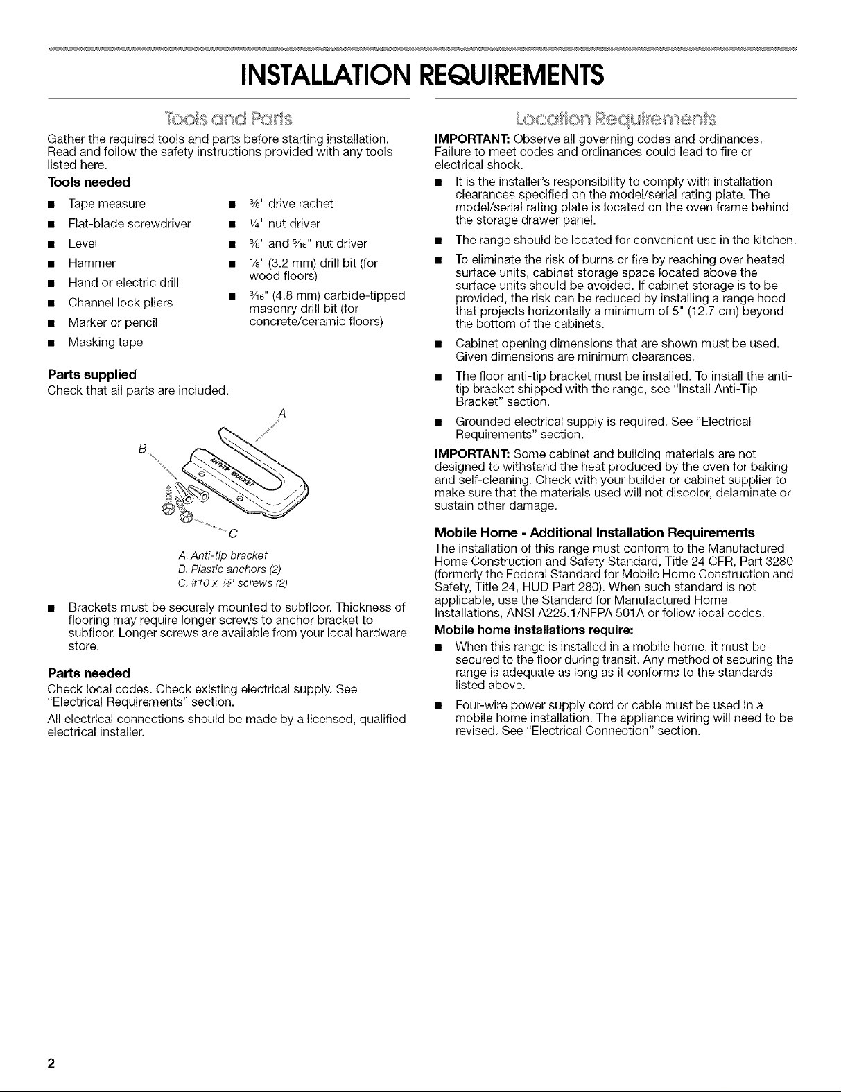
Parts supplied
Checkthat all parts are included.
A
A. Anti-tip bracket
B. Plastic anchors (2)
C. #10 x _" screws (2)
Brackets must be securely mounted to subfloor. Thickness of
flooring may require longer screws to anchor bracket to
subfloor. Longer screws are available from your local hardware
store.
Parts needed
Check local codes. Check existing electrical supply. See
"Electrical Requirements" section.
All electrical connections should be made by a licensed, qualified
electrical installer.
IMPORTANT: Observe all governing codes and ordinances.
Failure to meet codes and ordinances could lead to fire or
electrical shock.
• It is the installer's responsibility to comply with installation
clearances specified on the model/serial rating plate. The
model/serial rating plate is located on the oven frame behind
the storage drawer panel.
• The range should be located for convenient use in the kitchen.
• To eliminate the risk of burns or fire by reaching over heated
surface units, cabinet storage space located above the
surface units should be avoided. If cabinet storage is to be
provided, the risk can be reduced by installing a range hood
that projects horizontally a minimum of 5" (12.7 cm) beyond
the bottom of the cabinets.
Cabinet opening dimensions that are shown must be used.
Given dimensions are minimum clearances.
The floor anti-tip bracket must be installed. To install the anti-
tip bracket shipped with the range, see "Install Anti-Tip
Bracket" section.
• Grounded electrical supply is required. See "Electrical
Requirements" section.
IMPORTANT: Some cabinet and building materials are not
designed to withstand the heat produced by the oven for baking
and self-cleaning. Check with your builder or cabinet supplier to
make sure that the materials used will not discolor, delaminate or
sustain other damage.
Mobile Home - Additional Installation Requirements
The installation of this range must conform to the Manufactured
Home Construction and Safety Standard, Title 24 CFR, Part 3280
(formerly the Federal Standard for Mobile Home Construction and
Safety, Title 24, HUD Part 280). When such standard is not
applicable, use the Standard for Manufactured Home
Installations, ANSI A225.1/NFPA 501A or follow local codes.
Mobile home installations require:
• When this range is installed in a mobile home, it must be
secured to the floor during transit. Any method of securing the
range is adequate as long as it conforms to the standards
listed above.
• Four-wire power supply cord or cable must be used in a
mobile home installation. The appliance wiring will need to be
revised. See "Electrical Connection" section.
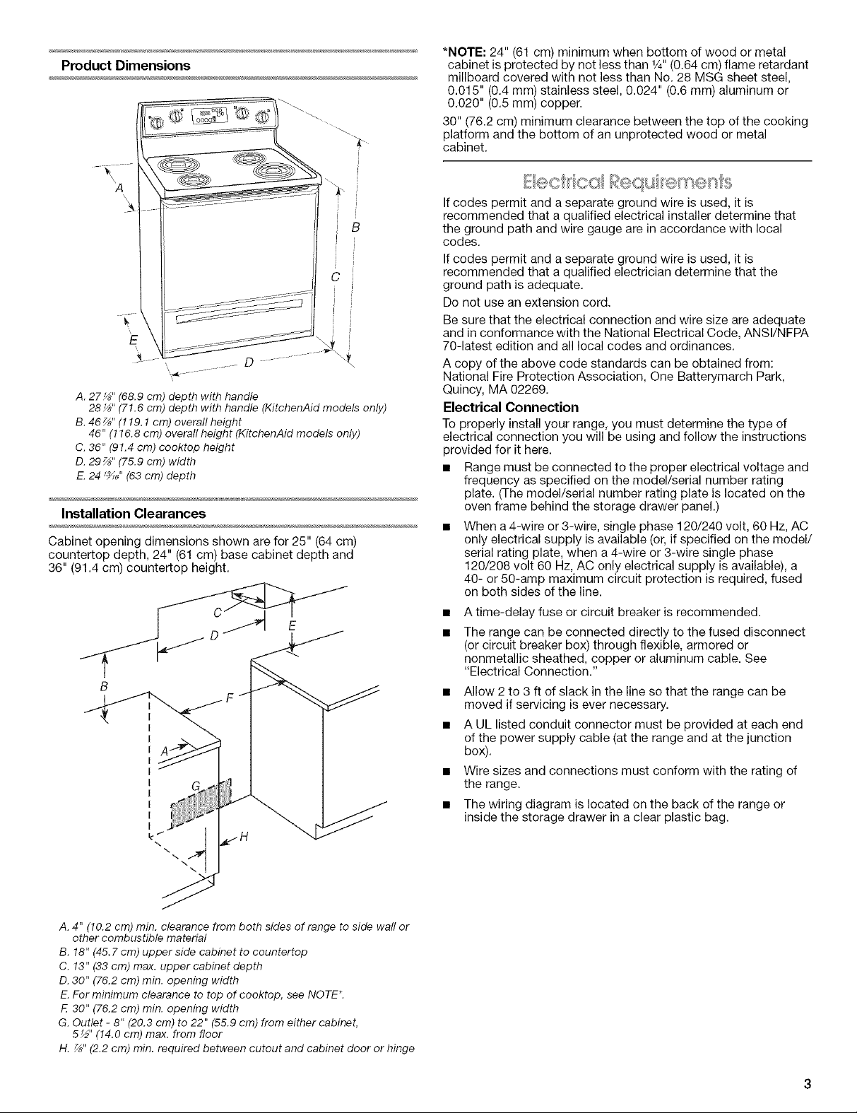
Product Dimensions
28_" (71.6 cm) depth with handle (KitchenAid models only)
B. 46%" (119.1 cm) overafl height
46" (116.8 cm) overall height (KitchenAid models only)
C. 36" (91.4 cm) cooktop height
D. 29%" (75.9 cm) width
E.24 1_/, (63 cm) depth
Installation Clearances
Cabinet opening dimensions shown are for 25" (64 cm)
countertop depth, 24" (61 cm) base cabinet depth and
36" (91.4 cm) countertop height.
A. 4" (10.2 cm) min. clearance from both sides of range to side wall or
other combustible material
B. 18" (45.7 cm) upper side cabinet to ceuntertop
C. 13" (33 cm) max. upper cabinet depth
D.30" (76.2 cm) min. opening width
E. For minimum clearance to top of cooktop, see NOTE*.
E 30" (76.2 cm) min. opening width
G. Outlet - 8" (20.3 cm) to 22" (55.9 cm) from either cabinet,
5½" (14.0 cm) max. from floor
H. %" (2.2 cm) min. required between cutout and cabinet door or hinge
*NOTE: 24" (61 cm) minimum when bottom of wood or metal
cabinet is protected by not less than 1/4"(0.64 cm) flame retardant
millboard covered with not less than No. 28 MSG sheet steel,
0.015" (0.4 mm) stainless steel, 0.024" (0.6 mm) aluminum or
0.020" (0.5 mm) copper.
30" (76.2 cm) minimum clearance between the top of the cooking
platform and the bottom of an unprotected wood or metal
cabinet.
If codes permit and a separate ground wire is used, it is
recommended that a qualified electrical installer determine that
the ground path and wire gauge are in accordance with local
codes.
If codes permit and a separate ground wire is used, it is
recommended that a qualified electrician determine that the
ground path is adequate.
Do not use an extension cord.
Be sure that the electrical connection and wire size are adequate
and in conformance with the National Electrical Code, ANSl/NFPA
70-latest edition and all local codes and ordinances.
A copy of the above code standards can be obtained from:
National Fire Protection Association, One Batterymarch Park,
Quincy, MA 02269.
Electrical Connection
To properly install your range, you must determine the type of
electrical connection you will be using and follow the instructions
provided for it here.
• Range must be connected to the proper electrical voltage and
frequency as specified on the model/serial number rating
plate. (The model/serial number rating plate is located on the
oven frame behind the storage drawer panel.)
• When a 4-wire or 3-wire, single phase 120/240 volt, 60 Hz, AC
only electrical supply is available (or, if specified on the model/
serial rating plate, when a 4-wire or 3-wire single phase
120/208 volt 60 Hz, AC only electrical supply is available), a
40- or 50-amp maximum circuit protection is required, fused
on both sides of the line.
A time-delay fuse or circuit breaker is recommended.
The range can be connected directly to the fused disconnect
(or circuit breaker box) through flexible, armored or
nonmetallic sheathed, copper or aluminum cable. See
"Electrical Connection."
• Allow 2 to 3 ft of slack in the line so that the range can be
moved if servicing is ever necessary.
• A UL listed conduit connector must be provided at each end
of the power supply cable (atthe range and at the junction
box).
• Wire sizes and connections must conform with the rating of
the range.
• The wiring diagram is located on the back of the range or
inside the storage drawer in a clear plastic bag.
If connecting to a 4-wire system:
This range is manufactured with the ground connected to the
cabinet. The ground must be revised so the green grounding wire
of the 4-wire power supply cord is connected to the cabinet. See
"Electrical Connection."
Grounding through the neutral conductor is prohibited for new
branch-circuit installations (1996 NEC); mobile homes; and
recreational vehicles, or an area where local codes prohibit
grounding through the neutral conductor.
When a 4-wire receptacle of NEMA Type 14-50R is used, a
matching UL listed, 4-wire, 250-volt, 40- or 50-amp, range power
supply cord (pigtail) must be used. This cord contains 4 copper
conductors with ring terminals or open-end spade terminals with
upturned ends, terminating in a NEMA Type 14-50R plug on the
supply end.
The fourth (grounding) conductor must be identified by a green or
green/yellow cover and the neutral conductor by a white cover.
Cord should be Type SRD or SRDT with a UL listed strain relief
and be at least 4 ft (1.22 m) long.
4-wire receptacle (14-50R)
The minimum conductor sized for the copper 4-wire power
cord are:
40-amp circuit
2 No,-8 conductors
1 No.-10 white neutral
1 No.-8 green grounding
If connecting to a 3-wire system:
Local codes may permit the use of a UL listed, 3-wire,
250-volt, 40- or 50-amp range power supply cord (pigtail). This
cord contains 3 copper conductors with ring terminals or open-
end spade terminals with upturned ends, terminating in a NEMA
Type 10-50P plug on the supply end. Connectors on the appliance
end must be provided at the point the power supply cord enters
the appliance. This uses a 3-wire receptacle of NEMA Type
10-50R.
3-wire receptacle (10-50R)
INSTALLATIONINSTRUCTIONS
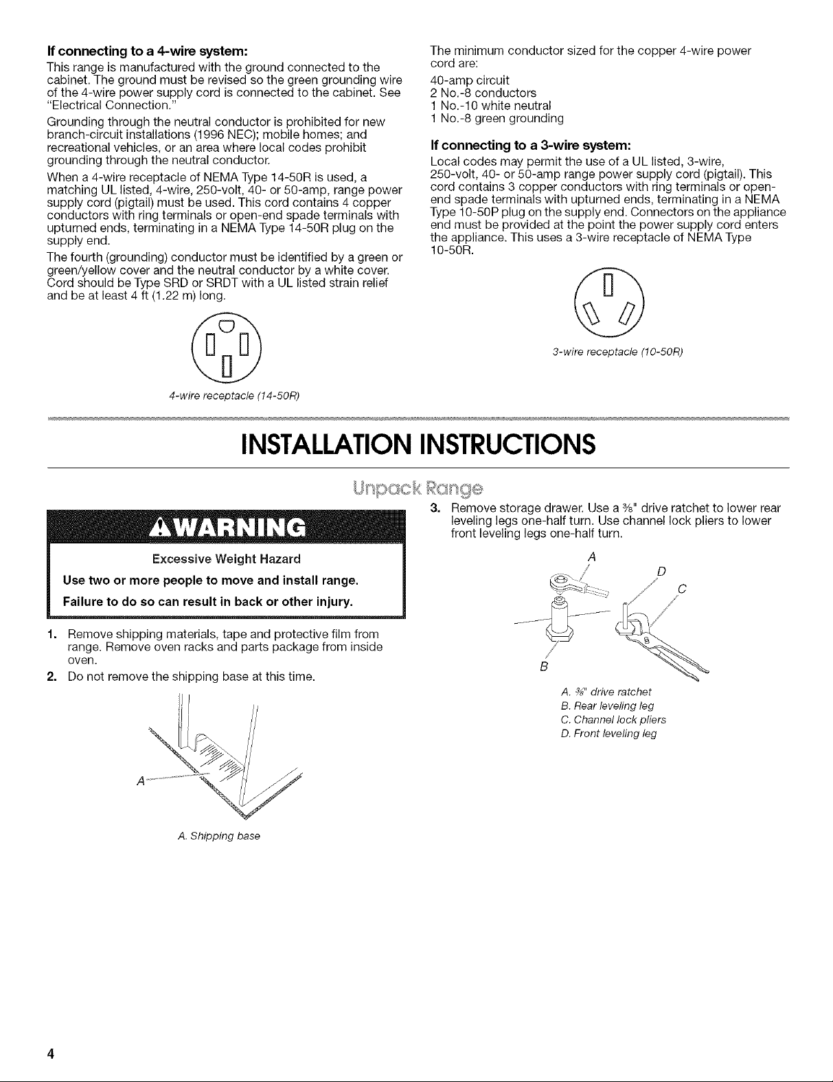
Excessive Weight Hazard
Use two or more people to move and install range.
Failure to do so can result in back or other injury.
1. Remove shipping materials, tape and protective film from
range. Remove oven racks and parts package from inside
oven.
2. Do not remove the shipping base at this time.
Remove storage drawer. Use a %" drive ratchet to lower rear
leveling legs one-half turn. Use channel lock pliers to lower
front leveling legs one-half turn.
A
/ D
B
A. _" drive ratchet
B.Rear levelingleg
C.Channellock pliers
D.Front levelingleg
A. Shipping base
 Loading...