


GOLD W4GH6
Whirlpool GOLD W4GH6, Gold W4GH624, Gold W4GH636, Gold W4GH648, Gold W4GH660 Installation Instructions Manual
HEAT PUMP INSTALLATION INSTRUCTIONS
Table of Contents
HEAT PUMP SAFETY.....................................................................1
INSTALLATION REQUIREMENTS................................................ 1
Tools and Parts ............................................................................2
System Requirements..................................................................2
Location Requirements................................................................2
Electrical Requirements ...............................................................4
Inspect Shipment.........................................................................4
Flush Refrigerant Lines ................................................................4
Connect Refrigerant Lines ...........................................................6
Make Electrical Connections .......................................................9
Complete Installation .................................................................11
HEAT PUMP SAFETY
Your safety and the safety of others are very important.
We have provided many important safety messages in this manual and on your appliance. Always read and obey all safety
messages.
This is the safety alert symbol.
This symbol alerts you to potential hazards that can kill or hurt you and others.
All safety messages will follow the safety alert symbol and either the word “DANGER” or “WARNING.”
These words mean:
SEQUENCE OF OPERATION ......................................................12
Cooling Cycle .............................................................................12
Heating Cycle .............................................................................12
Defrost Cycle..............................................................................12
Adjust Defrost System ...............................................................13
Troubleshoot the Defrost System..............................................14
TROUBLESHOOTING ..................................................................15
System Diagnostic Module........................................................15
SYSTEM MAINTENANCE ............................................................17
ASSISTANCE OR SERVICE.........................................................17
Accessories ................................................................................17
WARRANTY ..................................................................................18
You can be killed or seriously injured if you don't immediately
DANGER
WARNING
All safety messages will tell you what the potential hazard is, tell you how to reduce the chance of injury, and tell you what can
happen if the instructions are not followed.
follow instructions.
can be killed or seriously injured if you don't
You
instructions.
INSTALLATION REQUIREMENTS
These instructions are intended as a general guide only for use by
qualified persons and do not supersede any national or local
codes in any way. The installation must comply with all state and
local codes as well as the National Electrical Code
Whirlpool Gold™ Model W4GH6
48488A006
■ The heat pump is designed and approved for outdoor use
only.
■ The heat pump must be installed with no ductwork in the
airstream. The outdoor fan is not designed to operate against
any additional static pressure.
follow

Tools and Parts
Gather the required tools and parts before starting installation.
Read and follow the instructions provided with any tools listed
here.
Indoor System Thermal Expansion Valve
■ W4GH6 units are designed for use with thermal expansion
valve systems only. The thermal expansion valve must be
ordered separately from the manufacturer.
Tools Needed
■ To rc h
■ ¹⁄₄" nut driver
■ ⁵⁄₁₆" nut driver
■ Adjustable wrench
■ Gauge set for R-410A
refrigerant
■ Service wrench with hex-
head extension
■ Torque wrench
Parts Needed
Check local codes and HVAC supplier. Check existing electrical
supply, and read “Electrical Requirements,” “Location
Requirements,” “System Requirements” and “Connect
Refrigerant Lines.”
System Requirements
Heat pump system matches are derived from actual laboratory
testing of matched systems. It is recommended that only
matching equipment be used to ensure proper operation and
efficient performance.
■ The designed system matches are listed in the heat pump
unit specification sheets and on the heat pump refrigerant
charging instructions located on the back of the service
access panel.
■ Refrigerant charging instructions include a list of matching
indoor equipment with the proper thermal expansion valve
size and amount of refrigerant charge required.
■ This heat pump has been factory charged with a quantity of
refrigerant (R-410A) sufficient for a matched indoor coil and a
maximum 15 ft of refrigerant line.
■ In order to maintain the 16 SEER rating, this heat pump must
be matched with an indoor section containing a variable
speed blower.
■ Refer to the refrigerant charge label located on the inside of
the heat pump access panel for the correct thermal
expansion valve size required.
■ This product has been designed and manufactured to meet
ENERGY STAR
with appropriate coil components. However, proper
refrigerant charge and proper airflow are critical to achieve
rated capacity and efficiency. Installation of this product
should follow the manufacturer’s refrigerant charging and
airflow instructions. Failure to confirm proper charge and
airflow may reduce energy efficiency and shorten equipment
life.
■ A filter drier approved for use with R-410A refrigerant is
installed in the heat pump.
■ If this condensing unit is equipped with a crankcase heater, it
should be energized 24 hours before the condensing unit is
started to prevent compressor damage as a result of
slugging.
■ Use only polyol ester oils if oil must be added to the system.
Mineral oil is not compatible with refrigerant.
®
criteria for energy efficiency when matched
Thermal Expansion Valve Kits
Model Part Number
W4GH624 H4TXV01
W4GH636 H4TXV02
W4GH648, 60 H4TXV03
Location Requirements
■ This heat pump is designed to be located outdoors with
sufficient clearance for free entrance to the inlet and
discharge air openings. The location must also allow for
adequate service access. See “Minimum Clearances.”
■ Where possible, select a location for the heat pump which is
shaded from the direct rays of the sun most of the time. North
or east locations are usually most desirable. Position the heat
pump to avoid direct contact with water, snow or ice from a
roofline overhead.
■ The heat pump must be installed on a solid, level mounting
pad that will not settle or shift. Isolate the pad from the
building structure to avoid possible transmission of sound or
vibration from the heat pump into the conditioned space.
■ The heat pump foundation should be raised to a minimum of
3" above finish grade. In areas which have prolonged periods
of temperatures below freezing, and/or snowfall, the heat
pump should be elevated above the average snow line. If
heat pump is to be installed on a flat roof, it should be on a
platform or other support which will raise the inlet air opening
12" minimum above the surface of the flat roof.
■ Care should be taken to ensure free drainage of condensate
from defrost cycles. This will prevent ice accumulation. The
heat pump should be located away from walkways to prevent
possible icing from defrost condensate.
■ Avoid placing the heat pump near areas such as sleeping
quarters or study rooms. Normal operating sound levels may
be objectionable if the heat pump is placed near certain
rooms. A shift in sound type does occur during the defrost
mode. The defrost mode generally lasts no longer than
10 minutes.
2
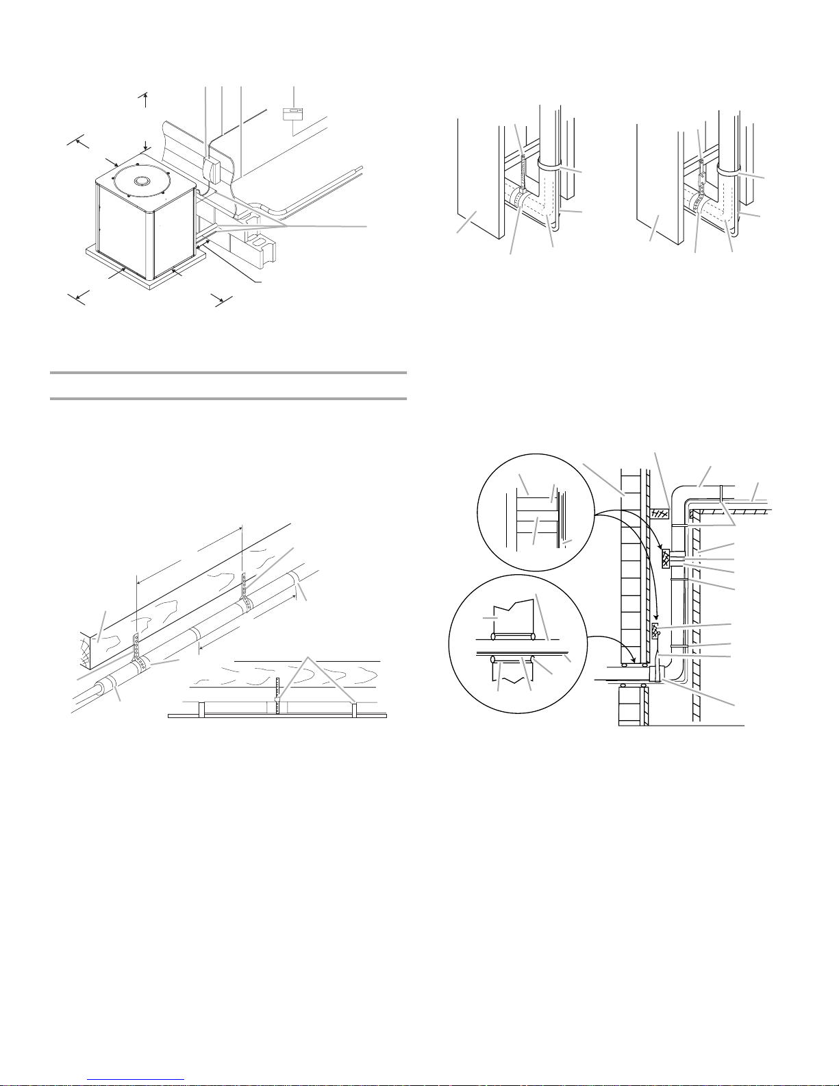
Minimum Clearances
C
B
AB C D
48" Overhead
Clearance
(Discharge
Air)
12" Clearance
(Inlet Air)
36" Clearance
(Inlet Air)
A. Weatherproof disconnect switch
B. NEC class 1 wiring
C. NEC class 2 wiring
30" Service
Access Clearance
To
Power
Supply
Indoor
12" Clearance Between
Unit and Building
D. House thermostat
E. Seal openings
To
Unit
To
Indoor
Coil
E
Line Set Isolation
The following illustrations demonstrate procedures which ensure
proper refrigerant line set isolation.
Installing Horizontal Runs
This shows how to install line sets on horizontal runs.
NOTE: To hang line set from joist or rafter, use either metal
strapping material or anchored heavy nylon wire ties.
C
8'
B
E
A
F
A. Metal strapping material
(around vapor line only)
B. Floor joist or roof rafter
C. Anchored heavy nylon wire tie
(around vapor line only)
D. Tape or wire tie
8'
E. Metal sleeve
F. Tape or anchored heavy nylon
wire tie
G. Strap the vapor line to the floor
joist or roof rafter at 8" intervals,
then strap the liquid line to the
vapor line.
D
G
Transition from Horizontal to Vertical
This shows how to make a transition from horizontal to vertical.
Style 1
A
Style 2
G
B
C
F
E
A. Style 1—anchored
heavy nylon wire tie
B. Strap liquid line to
vapor line.
D
C. Liquid line
D. Vapor line—
wrapped in
armaflex
F
E
E. Metal sleeve
F. Wall stud
G. Style 2—automotive
muffler-type hanger
D
Installing Vertical Runs (new construction shown)
This shows how to install line sets on vertical runs.
NOTE: Similar installation practices should be used if line set is
to be installed on exterior of outside wall.
IMPORTANT: Refrigerant lines must not contact structure.
B
C
D
E
F
G
H
E
I
E
G
H
I. Wood block
between studs
J. Caulk
K. Fiberglass
insulation
L. PVC pipe
C
G
C
A
K
L
A. Outside wall
B. Refrigerant lines
must not contact
wall.
C. Vapor line wrapped
in armaflex
A
H
D
D
J
D. Liquid line
E. Anchored heavy nylon
wire tie
F. Inside wall
G. Metal strapping material
H. Metal sleeve
3
Electrical Requirements
Inspect Shipment
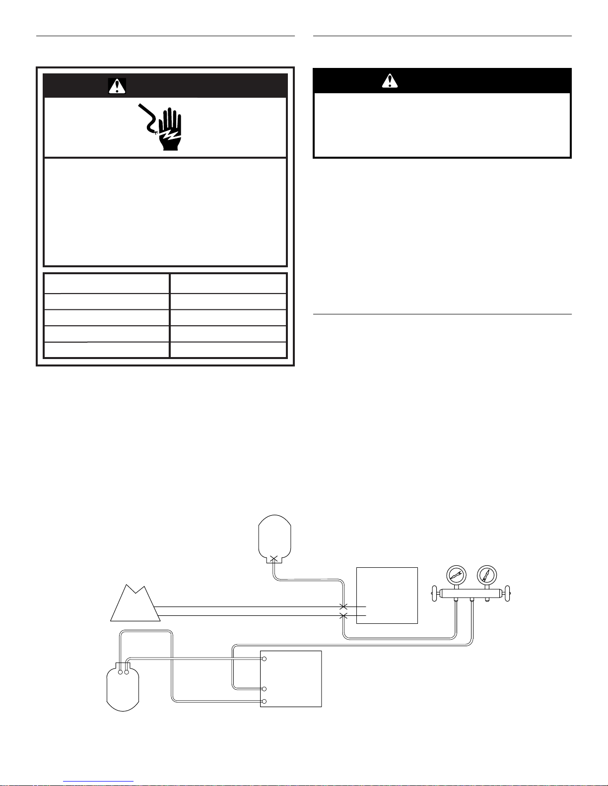
WARNING
Electrical Shock Hazard
Electrically ground condensing unit or heat pump.
Connect ground wire to ground lug.
Use copper wire for supply connection.
Correct wire gauge is shown in the chart below.
Failure to follow these instructions can result in
death or electrical shock.
Rating Plate Ampacity
Less than 15
16 - 20
21 - 30
31 - 50
NOTE: All outdoor wiring must be suitable for outdoor use. Use
copper conductors only.
■ All field wiring must be done in accordance with National
Electrical Code requirements, applicable requirements of UL,
or local codes, where applicable.
■ Electrical wiring, disconnect means and over-current
protection are to be supplied by the installer. Refer to the
rating plate for the maximum over-current protection,
minimum circuit ampacity, and operating voltage. See the
wiring diagrams in “Make Electrical Connections.”
AWG
14
12
10
8
WARNING
Excessive Weight Hazard
Use two or more people to move and install
condensing unit or heat pump.
Failure to do so can result in back or other injury.
This heat pump is shipped in one package, completely
assembled and wired. The thermostat is shipped in a separate
carton when ordered.
1. Check the heat pump rating plate to confirm specifications
are as ordered.
2. Upon receipt of equipment, carefully inspect it for possible
shipping damage. Take special care to examine the heat
pump inside the carton if the carton is damaged.
If damage is found, it should be noted on the carrier’s freight bill.
Damage claims should be filed with the carrier immediately.
Claims of shortages should be filed with the seller within 5 days.
NOTE: If any damages are discovered and reported to the carrier,
do not install the heat pump because your claim may be denied.
Flush Refrigerant Lines
Refrigerant lines must be flushed by a licensed, EPA certified
refrigerant technician in accordance with established procedures.
NOTES:
■ R-410A outdoor systems are not recommended for use with
indoor systems that have used R-22 as the refrigerant.
However, if this unit is being matched with an approved line
set or indoor coil which was previously charged with R-22
refrigerant, or if it is being matched with a coil which was
manufactured before January of 1999, the R-22 coil and line
set must be flushed prior to installation.
■ Check the refrigerant lines for size and length. See “Connect
Refrigerant Lines.”
Flushing Connections
Inverted R-22 Cylinder
(Contains clean R-22 to
be used for flushing)
Existing
Indoor Coil
Liquid
Vapor
Recovery Cylinder
4
Existing Vapor Line
Existing Liquid Line
Vapor Line
Service Valve
Liquid Line
Service Valve
Tank Return
Inlet
Discharge
Recovery Machine
Low
Pressure
Outdoor
System
NOTE: The inverted R-22 cylinder must contain at least
the same amount of refrigerant as was recovered from
the existing system.
Gauge Manifold
Opened
High
Pressure
Closed
1. Disconnect power.
D
C
A
B
2. Remove the refrigerant from the existing system per the
manufacturer’s instructions provided with the recovery
system being used. Connect the R-22 gauge set is
connected to both sides of the refrigerant system (as shown),
and verify that the entire system is void of refrigerant in
accordance with the manufacturer’s instructions provided
with the recovery system being used.
3. Disconnect the liquid and vapor lines from the existing
outdoor unit.
4. Remove the existing outdoor unit.
5. Set the new R-410A outdoor unit and connect the refrigerant
lines. See “Connect Refrigerant Lines” steps 1 through 5. Do
not evacuate the lines.
6. Remove the existing R-22 refrigerant flow control orifice or
thermal expansion valve on the indoor coil, and use a field
provided fitting to reconnect the lines.
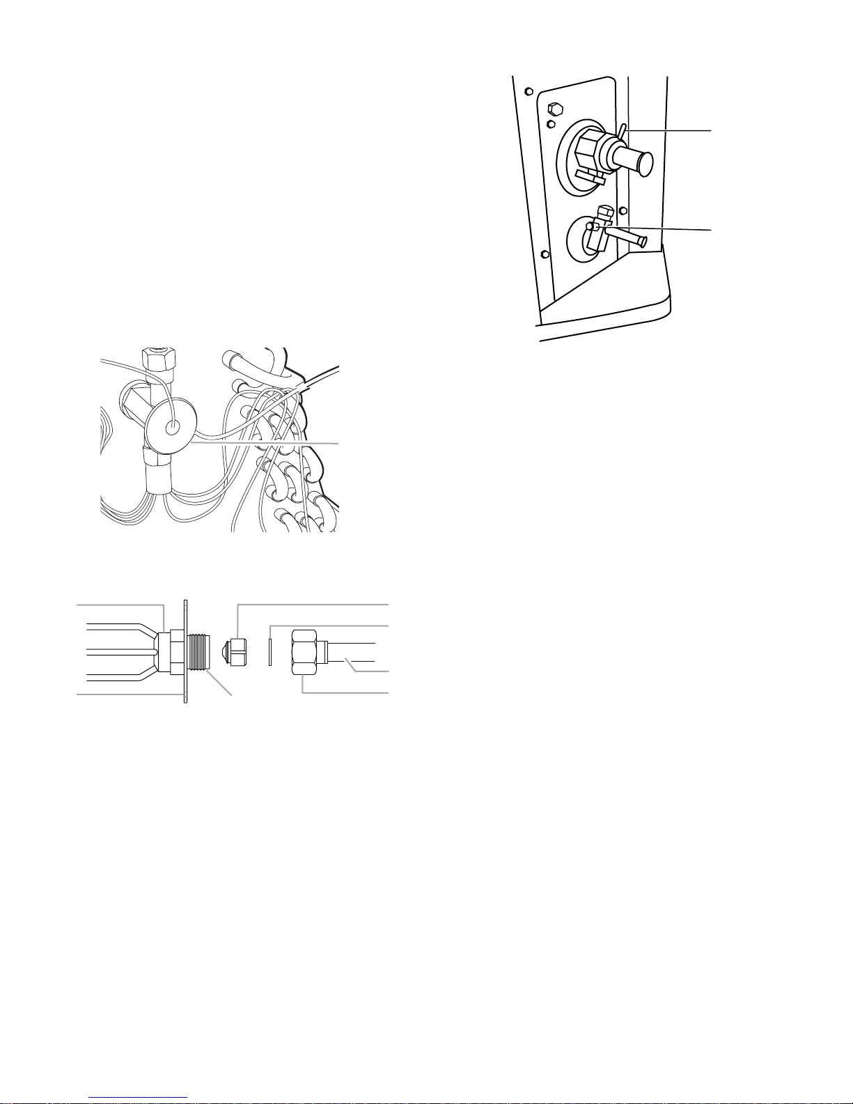
Thermal Expansion Valve
A
A. Thermal expansion valve
Orifice
A
E
B
A. Distributor fitting
B. Mounting flange
C. Piston orifice
D. Ring seal (supplied)
G
E. Orifice extension stub
F. 0.812" brass hex nut
G. Brass hex fitting
7. Remove the caps from the suction and liquid pressure taps.
F
8. Remove the valve cores.
A. Suction pressure tap
B. Liquid pressure tap
9. Connect an R-22 cylinder with clean refrigerant to the suction
pressure tap.
10. Connect the R-22 gauge set to the liquid line service valve
and connect a recovery machine with an empty recovery tank
to the gauge set.
11. Set the recovery machine for liquid recovery and start the
recovery machine in accordance with the manufacturer’s
instructions provided with the recovery system being used.
12. Open the gauge set valves to allow the recovery machine to
run until a vacuum level less than 0" Hg (gauge pressure) is
established in the existing system line set and indoor coil.
13. Invert the cylinder of clean R-22 and open its valve to allow
liquid refrigerant to flow into the system through the vapor
line valve.
14. After all of the liquid refrigerant has been recovered, switch
the recovery machine to vapor recovery to allow the recovery
machine to run until a vacuum level less than 0" Hg (gauge
pressure) is established in the existing system line set and
indoor coil in accordance with the manufacturer’s instructions
provided with the recovery system being used.
NOTE: A single system flush should remove all of the mineral oil
from the existing refrigerant lines and indoor coil. A second
flushing may be done (using clean refrigerant) if insufficient
amounts of mineral oil were removed during the first flush. A
second flushing may be required to ensure that the maximum
amount of oil is removed.
15. Close the valves on the inverted R-22 cylinder and gauge set.
16. Remove the recovery machine, gauges, R-22 cylinder and the
field provided fitting installed in Step 6.
5
17. Install the valve cores. 18. Install the R-410A thermal expansion valve specified for this
A
B
C
system in the indoor coil.
NOTE: R-410A systems use only thermal expansion valves.
19. Pressurize the lines and indoor coil with a pressure not to
exceed 20 psig.
20. Leak test the lines with a pressure not to exceed 20 psig.
21. Open the suction and liquid service valves fully.
22. Insulate the suction line with refrigerant line insulation
material of ¹⁄₄" or more wall thickness.
23. Pack insulating material around refrigerant lines where they
penetrate the structure to protect the lines and to minimize
vibration transmission.
A. Suction pressure tap
B. Liquid pressure tap
Connect Refrigerant Lines
Refrigerant lines must be connected by a licensed, EPA certified
refrigerant technician in accordance with established procedures.
IMPORTANT:
■ Connecting refrigerant lines must be clean, dehydrated,
refrigerant-grade copper lines. Heat pumps should be
installed only with specified line sizes for approved system
combinations with elevation differences up to 15 ft and total
length of up to 50 ft. See the Suction Line Sizes and Liquid
Line Sizes charts later in this section.
■ Avoid sharp bends or possible kinking in the refrigerant lines
during installation as this may cause a reduction in
performance.
■ Use care with the refrigerant lines during the installation
process. Sharp bends or possible kinking in the lines will
cause a reduction in performance.
■ To avoid contamination of the refrigerant system, do not
remove the caps from the lines or system connection points
until connections are ready to be completed.
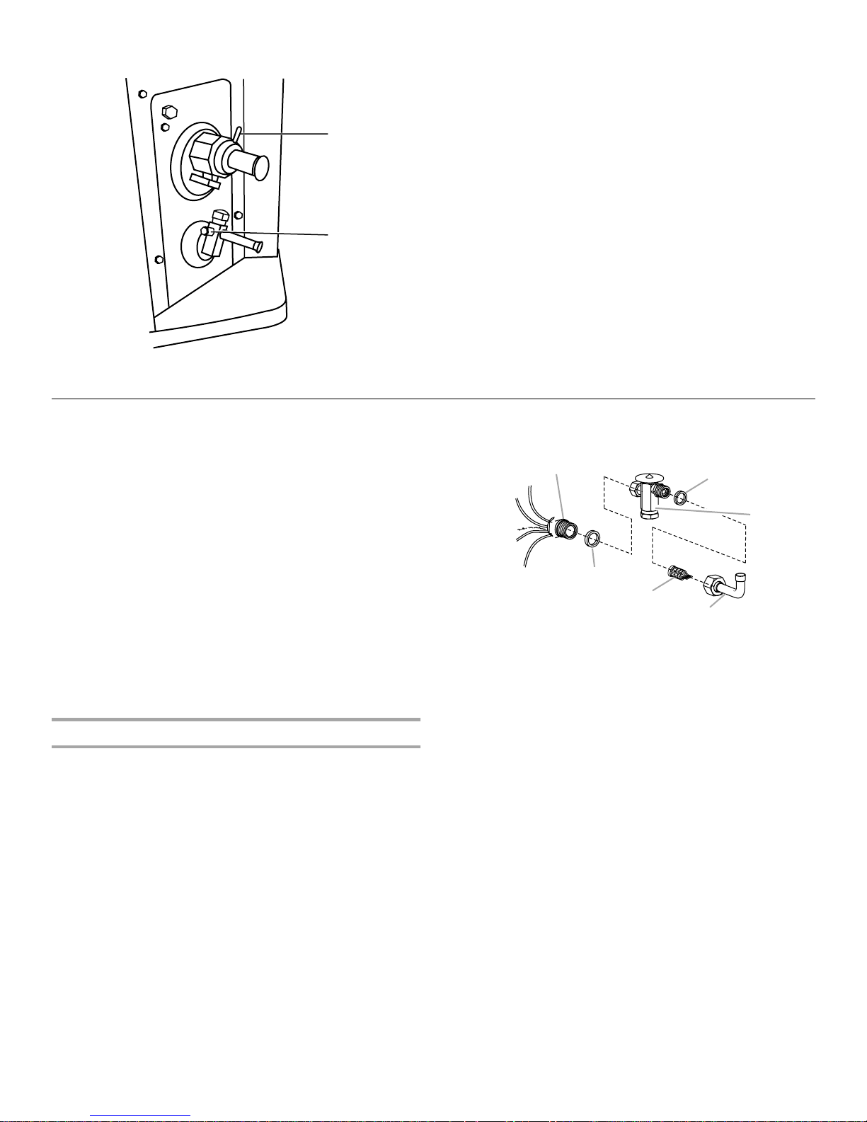
Install Thermal Expansion Valve
W4GH6 heat pumps are designed for use with thermal expansion
valve systems only. An R-410A system will not operate properly
with an R-22 thermal expansion valve.
Thermal expansion valves equipped with Chatleff-type fittings are
available from the manufacturer. See Thermal Expansion Valve
Kits chart in “System Requirements.”
Thermal Expansion Valve Installation
A
F
A. Distributor
B. Teflon
C. Thermal expansion valve
®
seal
E
D. Liquid line stub
E. Strainer
F. Te f l on
B
D
®
seal
To install the thermal expansion valve:
1. Separate the distributor assembly.
2. If a piston orifice is installed, remove the piston orifice and old
3. Insert nozzle end of the thermal expansion valve along with a
4. Tighten to 20 to 30 ft lbs. Use backup wrench on all wrench
5. Attach liquid line portion of distributor assembly along with
®
seal and discard.
Te fl on
®
new Teflon
seal into the distributor.
flats.
NOTE: Overtightening may crush the Teflon
a leak.
®
new Teflon
seal to the inlet of the thermal expansion valve.
®
seal and cause
6
®Teflon is a registered trademark of E.I. Dupont de Nemours and
Company.
 Loading...