


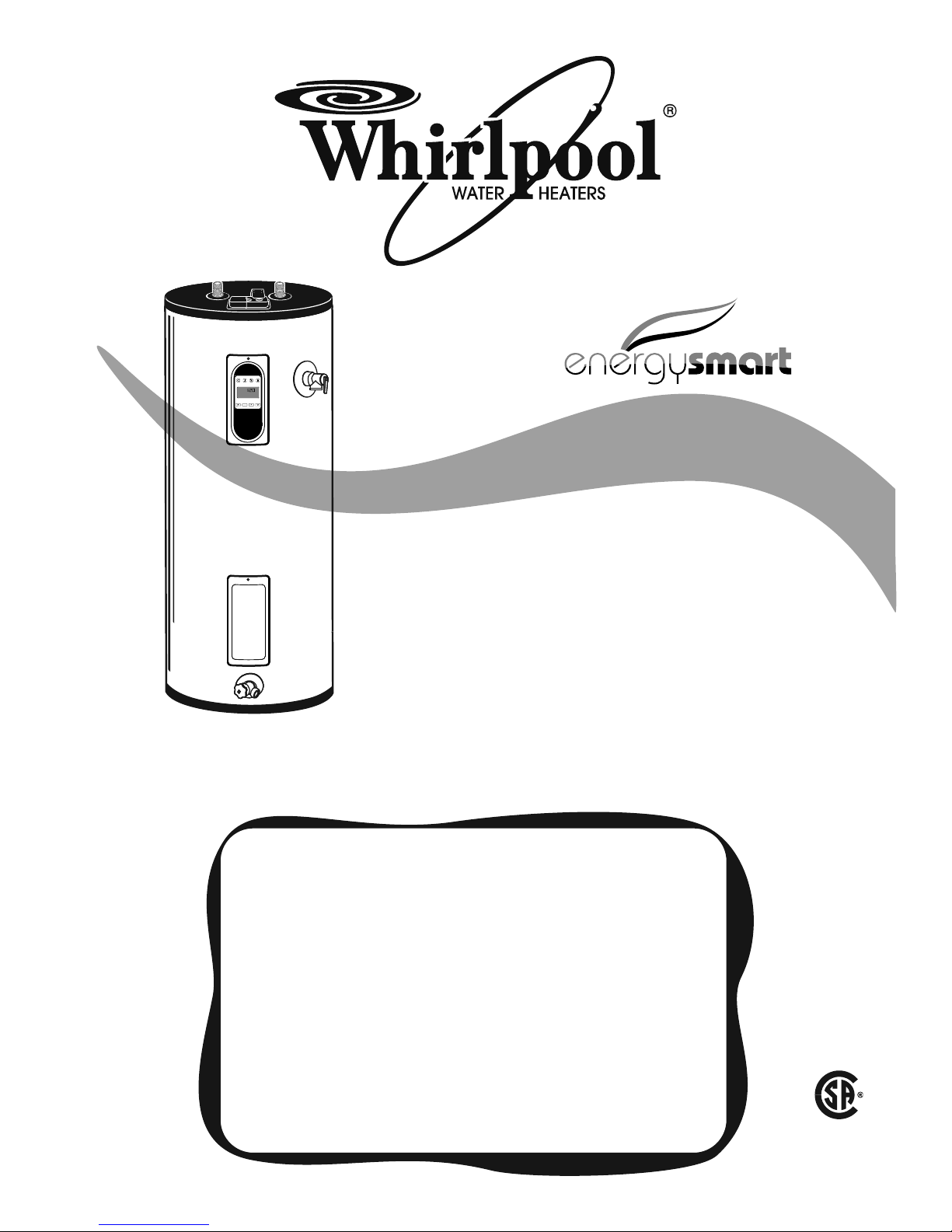
Energy Smart 188412
Whirlpool Energy Smart 188412, Energy Smart EE2H40RD045V, Energy Smart 188413, Energy Smart 188414, EnergySmart Installation And Use Manual
...
®
®
VACATION
STANDARD
ENERGY
GRID
SMART
ENABLED
F
°F/°C
Residential Electric
Water Heater
Installation
Instructions and
Use & Care Guide
To obstain technical, warranty, or service assistance during or after the
installation of this water heater, visit our website at:
http://www.whirlpoolwaterheatersupport.com
or call tool free
1-877-817-6750
When calling for assistance, please have the following information ready:
1. Model Number 4. Date of Installation
2. 7 Digit Product Number 5. Place of Purchase
3. Serial Number
Table Of Contents PAGE
Water Heater Safety ............................................................................ 2
Installing Your Electric Water Heater ................................................... 3-9
Unpacking Instructions ................................................................... 3
Location Requirements .................................................................. 4
Water System Piping ................................................................... 5
Electrical Requirements ................................................................. 7
Installation Checklist ...................................................................... 9
Operating Your Water Heater ............................................................. 10-12
Water Heater Start-Up ................................................................... 10
Water Temperature Regulation ...................................................... 10
Energy Smart
Electronic Thermostat .................................................................... 12
Smart Grid Technology .................................................................. 13
Operational Conditions ................................................................... 14
Maintenance of Your Water Heater .................................................... 15-23
Diagnostic Code (ESM)..................................................................17-18
Diagnostic Code (ET).................................................................... 19-20
Trouble Shooting Chart .....................................................................21
Repair Parts illustration ................................................................... 22
Thermostat Wiring Diagram ............................................................ 23
PRINTED IN THE U.S.A 0411 PART NO. 318686-000
®
Module/Operational Modes ................................... 11
1
LOW LEAD
COMPLIANT
WATER HEATER SAFETY
Your safety and the safety or others are very important.
We have provided many important safety messages in this manual and on your appliance. Always read and obey all
safety messages.
This is the safety alert symbol.
This symbol alerts you to potential hazards that can kill or hurt you and others.
All safety messages will follow the safety alert symbol and either the word “DANGER” or
“WARNING”. These words mean:
DANGER: indicates an imminently hazardous situation
which, if not avoided, will result in death or injury.
WARNING: indicates a potentially hazardous situation
which, if not avoided, could result in death or injury.
All safety messages will tell you what the potential hazard is, tell you how to reduce the chance of injury, and tell you
what can happen if the instructions are not followed.
IMPORTANT: Hydrogen gas is produced in a hot water system served by this heater that has not been used for a long
period of time (2 weeks or more). Hydrogen is extremely fl ammable. To reduce the risk of injury under these
conditions, it is recommended that the hot water faucet be opened for several minutes at the kitchen sink before using
any electrical appliance connected to the hot water system. When hydrogen is present, there will probably be an unusal
sound such as air escaping through the pipe as the water begins to fl ow. There should be no smoking or open fl ame
near the faucet at the time it is open.
The California Safe Drinking Water and Toxic Enforcement Act requires the Governor of California to publish a list of
substances known to the State of California to cause cancer, birth defects, or other reproductive harm, and requires
businesses to warn of potential exposure to such substances.
• WARNING: This product contains a chemical known to the State of California to cause cancer, birth defects, or other
reproductive harm.
• This appliance can cause low-level exposure to some of the substances listed in the Act.
Important Safety Instructions
2
INSTALLING YOUR WATER HEATER
Consumer Information
This water heater should be installed in accordance
with the local code authority having jurisdiction, the
power company or electric utility, and this installation
manual. In the absence of local code requirements,
follow the regulations set forth in the latest edition of the
National Electric Code, NFPA70. This is available from
the following:
National Fire Protection Agency
1 Batterymarch Park
Quincy, MA 02269
American National Standards Institute
1430 Broadway
New York, NY 10018
Check your phone listings for the local authorities
having jurisdiction over your installation.
Consumer Responsibilities
This manual has been prepared to acquaint you with
the installation, operation, and maintenance of your electric water heater and provide important safety information
in these areas.
We urge you to read all of the instructions thoroughly before attempting the installation or operation of this water
heater. This manual should be kept for future reference.
The manufacturer of this water heater will not be liable for
any damages caused by failure to comply with the installation and operating instructions outlined in this manual.
If you lack the necessary skills required to properly
install this water heater or you have difficulty following
the directions, you should not proceed but have a
qualified person perform the installation of this water
heater.
Examples of a qualified personnel include:
licensed plumbers, authorized electric company personnel, and authorized service person.
Massachusetts code requires this water heater to be
installed in accordance with Massachusetts Plumbing
and Fuel Code 248-CMR 2.00: State Plumbing Code and
248-CMR 5.00.
A data plate identifying your water heater can be found
adjacent to the energy smart module. When referring to
your water heater always have the information listed on
the data plate readily available, to include the model and
serial number.
Retain your original receipt as proof of purchase.
Insulation Blankets
The use of an insulation blanket on this water heater is
not needed nor recommended. The purpose of an insulation blanket is to reduce the standby heat loss encountered with storage tank heaters. Your water heater meets
or exceeds the National Appliance Energy Conservation
Act standards with respect to insulation and standby loss
requirements, making an insulation blanket unnecessary.
Unpacking the Water Heater
Removing Packaging Materials
Use two or more people to move and install
water heater.
Failure to do can result in back or
other injury.
IMPORTANT: Do not remove any permanent instructions,
labels, or the data label from outside of the water heater or
on the inside of panels.
• Remove exterior packaging and place installation
components aside.
• Do not remove the envelope bag containing the
water heater literature from the side of the water
heater.
• Inspect all parts for damage prior to installation and
start-up.
• Completely read and understand all instructions
before attempting to assemble and install this product.
• Replace this manual inside the envelope bag when
installation is complete.
• After installation, dispose of packaging material in
the proper manner.
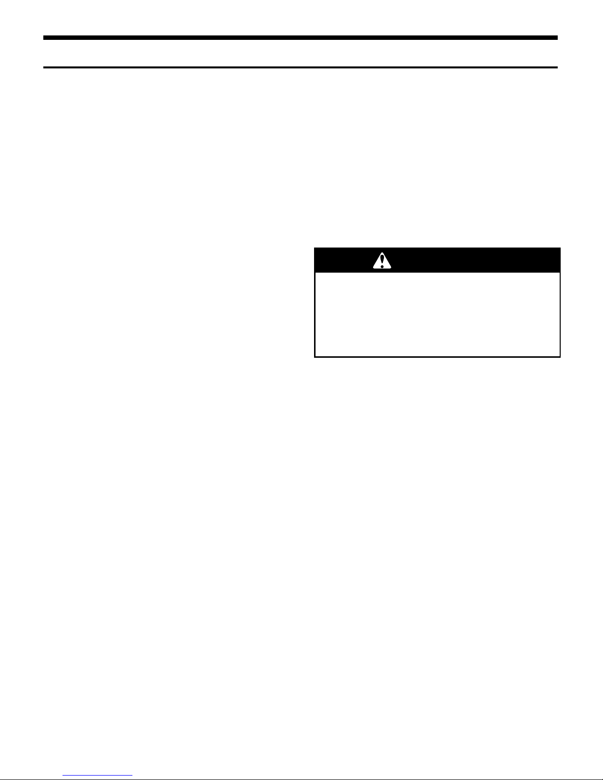
WARNING
Excessive Weight Hazard
3

Location Requirements
Site location
Select a location near the center of the water piping
system. It must be installed indoors and in a vertical
position on a level surface, in an area where water
leakage will not cause consequential damage.
NOTE: Local codes and requirements in your area may
require the water heater to be installed such that the
bottom element is elevated from the floor at least 18
inches.
The water heater should be located in an area not
subject to freezing temperatures. Water heaters located
in unconditioned spaces (i.e., attics, garages, basements, etc.) may require the water piping and drain
piping to be insulated to protect against freezing. The
drain and controls must be easily accessible for operation and service.
Keep combustibles such as boxes, magazines, clothes,
etc., away from the water heater area.
Do not use this water heater in conjunction with a spa or
hot tub.
IMPORTANT: The water heater should be located in
an area where leakage of the tank or connections will
not result in damage to the area adjacent to the water
heater or to lower floors of the structure. Due to the
normal corrosive action of the water, the tank will
eventually leak after an extended period of time.
Also, any external plumbing leak, including those
from improper installation, may cause early
failure of the water tank due to corrosion if not
repaired. If the homeowner is uncomfortable with
making the repair, a qualified person should be
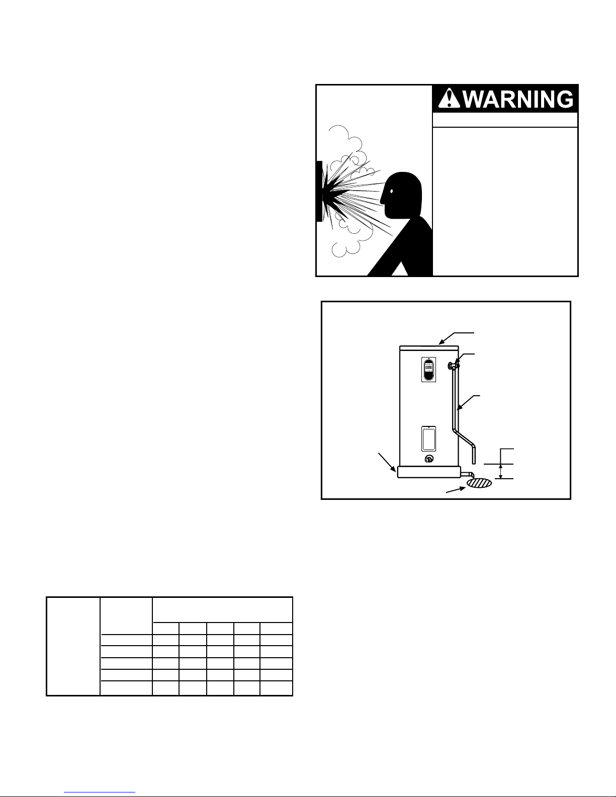
contacted. A suitable metal drain pan should be
installed under the water heater as shown below. This
metal drain pan is to protect the property from damage
which may occur from normal condensate formation
on the tank or leaks in the tank and pipe connections.
The metal drain pan must limit the water level to a
maximum depth of 2-1/2 inches and be two inches
wider than the heater and piped to an adequate drain.
Locate the water heater near a
suitable indoor drain. Outdoor drains are subject to
freezing temperatures which can obstruct the drain
line. The piping should be at least 3/4”ID and pitched
for proper drainage.
Under no circumstance will the manufacturer or
seller of this water heater be held liable for any
water damage that is caused by your failure to
follow these instructions.
NOTE: The water heater shall be located so it is not
subject to physical damage by moving vehicles or area
flooding.
Figure 2
Residential Garage
Installation
VACATION
STANDARD
ENERGY
GRID
SMART
EMABLED
F
°F/°C
Vehicle
Stop
Metal Drain Pan
Drain
State of California
NOTE: The water heater must be braced, anchored, or
strapped to avoid moving during an earthquake. Contact
local utilities for code requirements in your area or call
1-877-817-6750 and request instructions.
2 1/2” Max
At least 2” inches greater than
the diameter of the water
Figure 1
heater.
Pipe to
adequate
drain
4
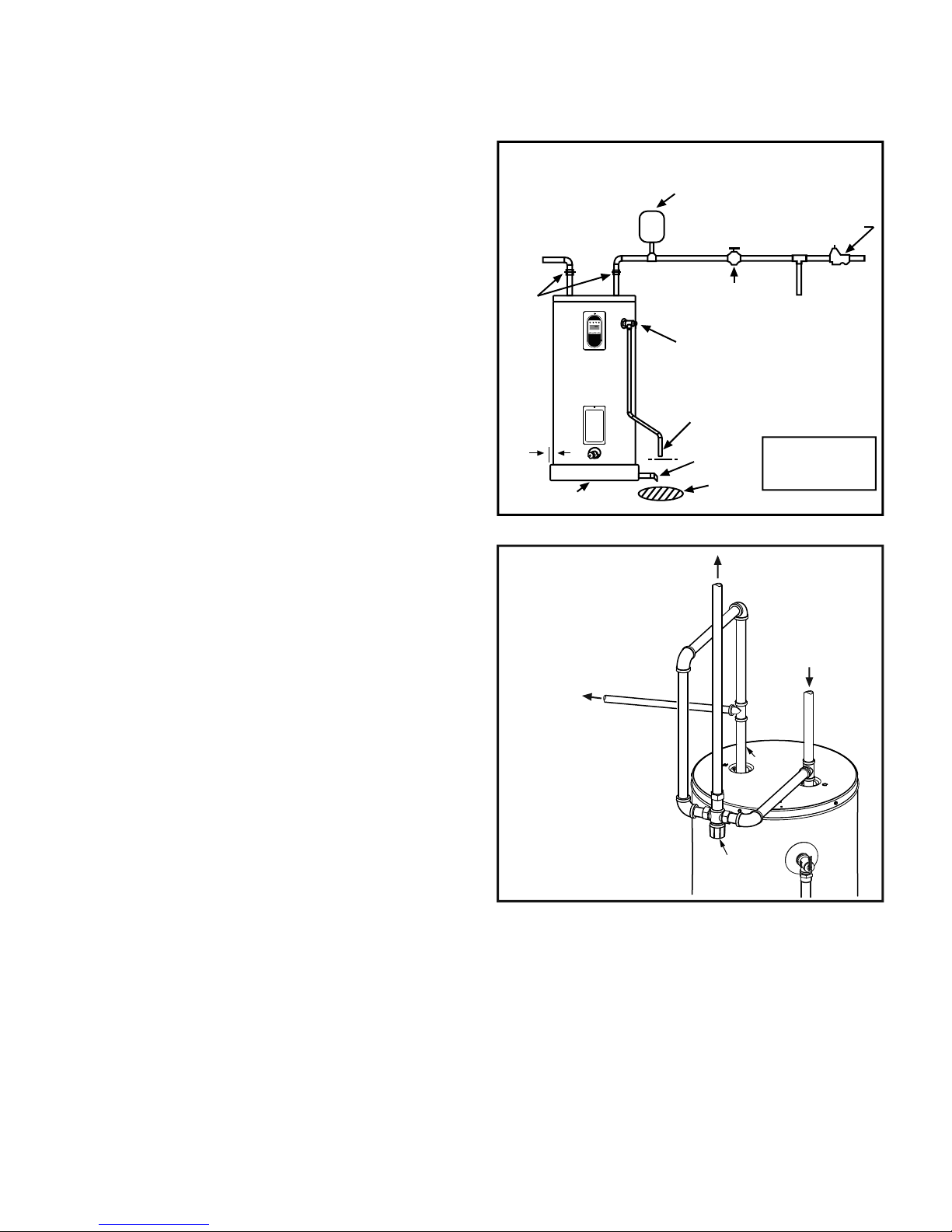
Water System Piping
Piping Installation
Piping, fi ttings, and valves should be installed according
to the installation drawing (Figure 3). If the indoor installation area is subject to freezing temperatures, the
water piping must be protected by insulation.
Water supply pressure should be around 50 to 60 psi
and should not exceed 80 psi. If this occurs, a pressure
reducing valve should be installed in the cold water inlet
line. This should be placed on the supply to the entire
house in order to maintain equal hot and cold water
pressures.
IMPORTANT: Heat cannot be applied to the water fi ttings
on the heater as they may contain nonmetallic parts.
If solder connections are used, solder the pipe to the
adapter before attaching the adapter to the hot and cold
water fi ttings.
IMPORTANT: Always use a good grade of joint com-
pound and be certain that all fi ttings are drawn up tight.
1. Install the water piping and fitting as shown in
Figure 3. Connect the cold water supply (3/4” NPT)
to the fitting marked “Cold”. Connect the hot water
supply (3/4” NPT) to the fitting marked “Hot”.
IMPORTANT: Some models may contain energy saving
heat traps to prevent the circulation of hot water within
the pipes. Do not remove these inserts.
2. The Installation of dielectric unions in both the hot
and cold water supply lines is recommended for
ease of removing the water heater for service or
replacement.
3. Some local codes may require, and the manufac turer of this water heater recommends,
installing a mixing valve in the domestic hot water
line as shown in Figure 4. These valves reduce the
point-of-use temperature of the hot water by mixing
cold and hot water and are readily available.
Contact a licensed plumber or the local plumbing
authority.
4. If installing the water heater in a closed water
system, install a relief valve or expansion tank in
the cold water line as specified under “Closed
System/Thermal Expansion”.
5. Install a shut-off valve in the cold water inlet line. It
should be located close to the water heater and be
easily accessible. Know the location of this valve
and how to shut off the water to the heater.
6. Install a discharge line from the temperature and
pressure relief valve in the opening marked “T & P
RELIEF VALVE”. Install as specified under
“Temperature and Pressure Relief Valve”.
7. After piping has been properly connected to the
water heater, open the nearest hot water faucet.
Then open the cold water shut off valve and
allow the tank to completely fill with water. To purge
the lines of any excess air and sediment, keep the
hot water faucet open for 3 minutes after a constant
flow of water is obtained. Close the faucet and
check all connections for leaks.
Figure 3
Water Piping Installation
Hot Water
Outlet
Union
VACATION
STANDARD
ENERGY
GRID
SMART
ENABLED
F
°F/°C
1”
Min.
Metal Drain Pan
2-1/2” depth max.
Figure 4
Mixing Valve
Top Water Connections
Unmixed
Hot Water
Follow The Mixing Valve
Manufacturer’s Instructions
In a Closed System use a
Thermal Expansion Tank.
Cold Water
Inlet Valve
Temperature and
Pressure Relief Valve
Discharge line 6” maximum
above drain
Drain line
3/4” ID
minimum
Drain
Mixed Water
To Fixtures
Mixing Valve
(Set To 120 F)
Pressure Reducing
Valve With Bypass
Cold Water
Supply to
Fixtures
Massachusetts:
Install vacuum relief
in cold water line per
section 19 MGL 142.
Cold Water
Hot
Water
Outlet
0
Inlet
Main
Water
Supply
5
Please note the following:
DO NOT install this water heater with iron piping.
The system should be installed only with piping that
is suitable for potable (drinkable) water such as
copper, CPVC, or polyethylene (PEX).
DO NOT use PVC water piping.
DO NOT use any pumps, valves, or fi ttings that are
not compatible with potable water.
DO NOT use valves that may cause excessive
restriction to water fl ow. Use full-fl ow ball or gate
valves only.
DO NOT use tin-lead solder in potable water lines.
Use 95/5 tin antimony or other equivalent material.
DO NOT tamper with the energy smart module,
electronic thermostat, temperature sensors, heat ing elements, electrical connections, or temperature
and pressure relief valve. Tampering voids all war ranties. Only qualifi ed person should service these
components.
DO NOT use with piping that has been treated with
chromate’s, boiler seal, or other chemicals.
DO NOT add any chemicals to the system piping
which will contaminate the potable water supply.
Closed System/Thermal Expansion
Typically, a closed system includes a pressure reducing
valve (PRV) on the cold water inlet (supply line). As water
is heated, it expands (thermal expansion). In a closed system, the volume of water will grow. As the volume of water
grows, there will be a corresponding increase in water
pressure due to thermal expansion. Thermal expansion
can cause premature tank failure (leakage). This type of
failure is not covered under the limited warranty. Thermal
expansion can also cause intermittent temperaturepressure relief valve operation: water discharged from the
valve due to excessive pressure build up. The temperature-pressure relief valve is not intended for the constant
relief of thermal expansion. This condition is not covered
under the limited warranty.
A properly-sized thermal expansion tank should be installed on all closed systems to control the harmful effects
of thermal expansion. Contact a plumbing service agency
or your retail supplier regarding the installation of a thermal expansion tank.
Expansion Tank Sizing Chart
Inlet Water Heater Capacity (Gallons)
Water
Pressure 30 40 50 66 82
Expansion 40psi 2 2 2 5 5
Tan k 50psi 2 2 2 5 5
Capacity 60psi 2 2 5 5 5
Needed 70psi 2 2 5 5 5
80psi 2 5 5 5 5
A thermal expansion tank can help prevent damage to the
water heater and other appliances (i.e.: washing machine,
ice maker, dishwasher, etc.).
IMPORTANT: Do not plug or remove the temperature and
pressure relief valve (T&P valve).
Temperature and Pressure
Relief Valve
Explosion Hazard
• Temperature-pressure relief
valve must comply with ANSI
Z21.22-CSA 4.4 and ASME
code.
• Properly sized temperaturepressure relief valve must be
installed in opening provided.
• Can result in overheating
and excessive tank pressure.
• Can cause serious injury or
death.
Figure 5
Temperature and Pressure
Relief Valve Installation
VACATION
STANDARD
ENERGY
GRID
SMART
ENABLED
F
°F/°C
Drain Pan
Drain
For protection against excessive pressures and
temperatures, a temperature and pressure relief valve
must be installed in the opening marked “T&P RELIEF
VALVE” (See Figure 5). This valve must be design certifi ed by a nationally recognized testing laboratory that
maintains periodic inspection of the production of listed
equipment or materials as meeting the requirements
for Relief Valves for Hot Water Supply Systems, ANSI
Z21.22. The function of the temperature and pressure
relief valve is to discharge water in large quantities in the
event of excessive temperature or pressure developing in the water heater. The valve’s relief pressure must
not exceed the working pressure of the water heater as
stated on the rating plate.
IMPORTANT: Only a new temperature and pressure
relief valve should be used with your water heater. Do
not use an old or existing valve as it may be damaged or
not adequate for the working pressure of the new water
heater. Do not place any valve between the relief valve
and the tank.
6
Optional location some
models only
Temperature and
Pressure Relief Valve
Discharge Line
3/4 inch min.
Do not cap or plug.
6 inch
maximum
The Temperature & Pressure Relief Valve:
• Must be connected to an adequate discharge line.
• Must not be in contact with any electrical part.
• Must not be rated higher than the working pressure
shown on the data plate of the water heater.
The Discharge Line:
• Must not be smaller than the pipe size of the relief
valve or have any reducing coupling installed in the
discharge line.
• Must not be capped, blocked, plugged, or contain
any valve between the relief valve and the end of
the discharge line.
• Must terminate a maximum of six inches above a
fl oor drain or external to the building. In cold climates,
it is recommended that the discharge pipe be termi nated at an adequate drain inside the building.
• Must be capable of withstanding 250° F (121°
without distortion.
• Must be installed to allow complete drainage of
both the valve and discharge line.
C)
T&P Relief Valve and Pipe Insulation:
6. Spread the slit open and slip the insulation over
the cold water (inlet) pipe. Apply gentle pressure
along the length of the insulation to ensure it is fully
seated around the pipe. Also ensure that the base of
insulation is flush with the water heater. Once seated,
secure the insulation with duct tape, electrical tape, or
equivalent.
7. Repeat steps 5 through 6 for the hot water (outlet)
pipe.
8. Add additional sections of pipe insulation as needed.
Solar Installation
If this water heater is used as a solar storage heater or
as a backup for the solar system, the water supply
temperatures to the water heater tank may be in excess
of 120° F (48.8° C). A mixing valve or other temperature
limiting valve must be installed in the water supply line to
limit the supply temperature to 120° F (48.8° C).
Note: Solar water heating systems can often supply water
with temperatures exceeding 180° F (82.2° C) and may
result in water heater malfunction.
1. Locate the temperature and pressure relief valve on
the water heater (also known as a T&P Relief Valve,
(Figure 6).
2. Locate the slit running the length of the insulation.
3 Spread this slit open and slip it up under the T&P
Relief Valve (See Figure 6). Apply gentle pressure to
the insulation to ensure it is fully seated on the T&P
Relief Valve. Once sealed, secure the insulation with
a section of duct tape, electrical tape, or equivalent.
IMPORTANT: The insulation or tape must not block
the discharge opening or hinder access to the manual
relief lever. Ensure a discharge pipe is installed into
the T&P valve discharge opening per the instructions
manual.
4. Locate the hot water (outlet) & cold water (inlet) pipes
to the water heater.
5. Locate the slit running the length of a section of pipe
insulation.
Figure 6
Temperature and Pressure
Relief Valve Installation
Manual Relief Lever
T&P Relief Valve
T&P Relief Valve
Drain Line
T&P Relief Valve Insulation
Electrical Requirements
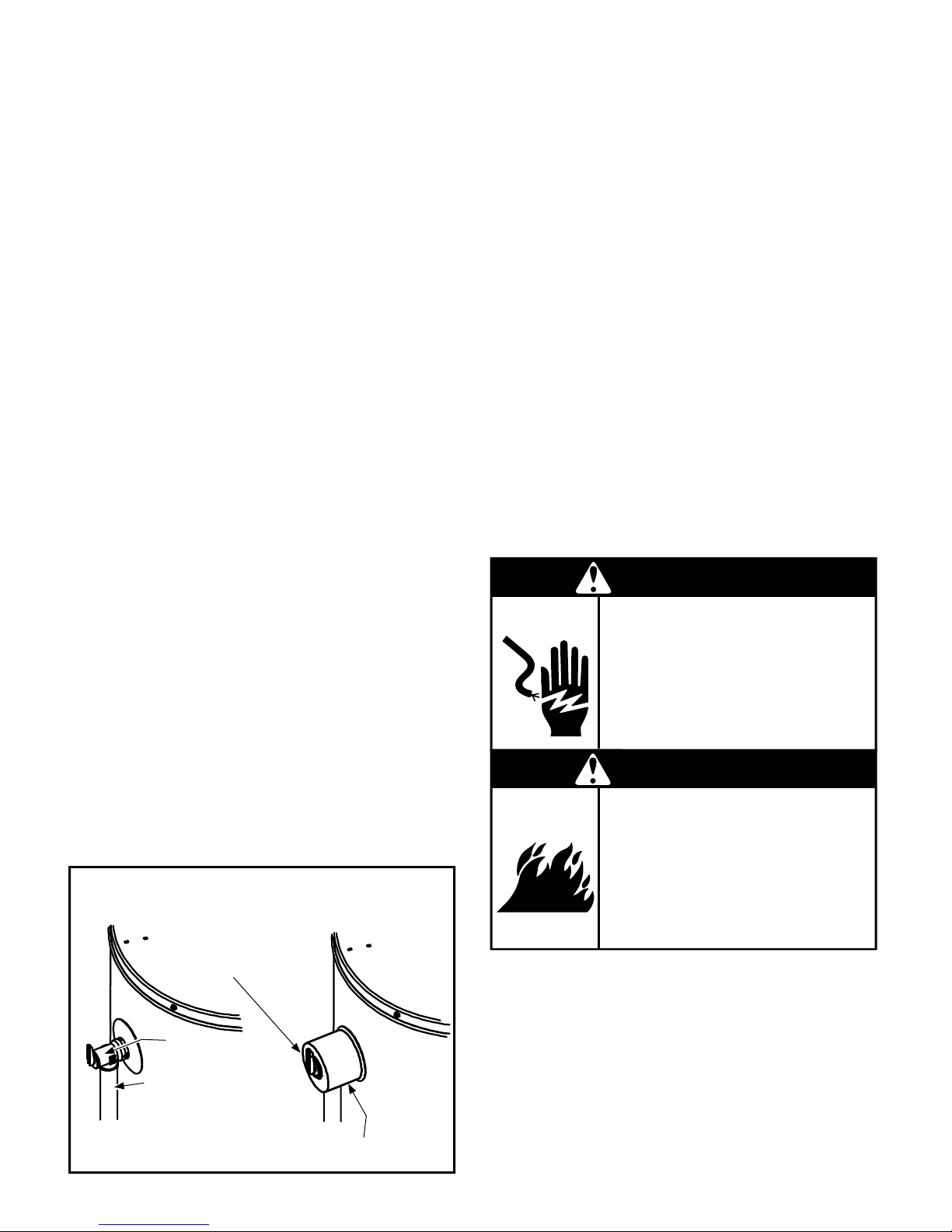
WARNING
Electric Shock Hazard
Disconnect power before
servicing.
Replace all parts and panels
before operating.
Failure to do so can result in
death or electric shock.
WARNING
Fire Hazard
Use 10 gauge solid copper wire.
Use a UL approved strain relief.
Connect ground wire to green
ground screw.
Failure to do so can result in
death, fire, or electrical shock.
If you lack the necessary skills required to properly
install the electrical wiring to this water heater, do not
proceed, but have a qualifi ed electrician perform the
installation.
When making the electrical connections, always make
sure:
• The electrical supply has the proper overload fuse
or circuit breaker protection.
• Wire sizes and connections comply with all
applicable codes.
7
• Wiring is enclosed in approved conduit (if required
by local codes).
• The water heater and electrical supply are properly
grounded.
Always reference the wiring diagram for the correct electrical connection. The complete wiring diagram can also be
found on the top of the water heater near the junction box
cover.
When installing the electrical wiring to the water heater
• Although this water heater is equipped with “Dry-fi re”
protection, be sure the tank is completely fi lled with
water, and all air is purged from the tank before
making any electrical connections (See Figure 7).
Figure 7
Heating Element
Bang
Figure 8
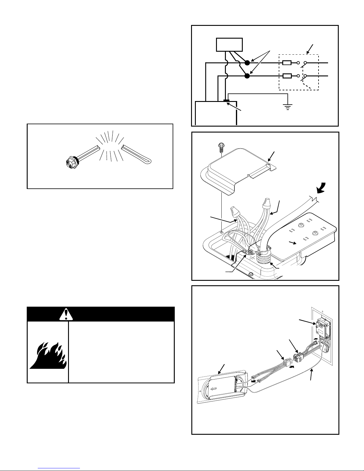
Wiring Diagram
Black
Water Heater
Figure 8A
Junction Box
Smart Grid
Wire Harness
Red
Green
Black
Red
Ring Terminal
at Ground
Screw
Approved
Connectors
Junction Box Cover
Electrical
Service ground
Circuit
Breaker
L1
L2
To 240v
1 Phase
Power
supply
NOTE: Applying electrical power to elements that are not submerged
in water will destroy them. The manufacturer will not warranty any
elements damaged in this manner.
1. Check and turn off power to the electrical wiring of the
water heater before making any electrical connections
to the water heater.
2. Remove the junction box cover that is secured by one
screw (Figure 8A). Place the cover and screw aside
and view the wiring diagram. Locate the four power
wires inside the junction box (there will be TWO red
wires and TWO black wires).
3. Connect the electrical supply to the water heater in
accordance with the local utility requirements and
codes. A standard 1/2 inch opening has been made
in the junction box for the conduit connections (Fig ure 8A). NOTE: Use only 10 gauge solid copper wire
for the electrical connections and an appropriate size
double pole circuit breaker.
WARNING
Fire Hazard
Use 10 gauge solid copper wire.
Use a UL approved strain relief.
Connect ground wire to green
ground screw.
Failure to do so can result in
death, fire, or electrical shock.
4. Ground the water heater by connecting the bare cop per ground wire from the home’s electrical service to
the green ground screw (located on the electrical jun-
ction box on top of the water heater). See Figures 8
and 8A.
5. There are TWO black wires and TWO red wires in the
water heater. The smaller red and black wires are
used by the Smart Grid connector.
Black Wires
(3)
Ground Wires
Figure 8B
Electronic Thermostat (ET)
Energy Smart®
Module (ESM)
Red Wires
(3)
Electronic
Thermostat (ET)
Wiring Harness
( Junction Box )
Wiring Harness
( ET to ESM )
From Home
Electrical Service
Smart Grid
Cover
1/2” Conduit
Connection
( Attached To T-Stat Bracket Screw )
Ground Wire
8
 Loading...