


4
BEFORE USING THE APPLIANCE
To make the most out of your new appliance,
please read the user instructions carefully and keep
them handy for future consultation.
Before using the appliance please follow and
set according to the below indications:
Remote Control (RC) presetting:
Each time the batteries are replaced in the remote
control, the RC is pre-set on Heat pump.
If the air conditioner that you purchased is a
cooling only, then the pre-set on Heat pump will
not bring any changes.
Auto-Restart presetting Function:
To set the auto-restart function, press the
Emergency button (ON/OFF) on the indoor unit
for at least 5 seconds
A buzz sound will signal that the auto-restart
function is set and the air conditioner is in standby.
To cancel the auto-restart function, repeat the
above steps.
SAFETY PRECAUTIONS
• Do not install the appliance if it is connected to
the power supply.
• The Installation and service/repair must be
performed by a qualified technician, in
compliance with the producer's instructions and
following local safety norms. Do not repair or
replace any parts of the appliance unless it is
specifically written in the user instructions.
• The grounding of this appliance is compulsory.
• Make sure that the power supply cord is long
enough to allow the right connection. Do not
use any extension cord for power supply.
• Do not pull the power supply cord to remove it
from the socket.
• Do not twist or press the power supply cord,
and make sure it is not broken.
• Once installation is completed, the electric
components must not be accessible to the users.
• Do not touch the operation buttons when your
hands are wet and don't use the appliance when
you are barefoot.
• Physically or mentally disabled people, children
and people without any experience with the
product are only allowed to use the appliance if
they have had specific training on how to
operate the appliance by a person responsible
for their security and well-being. The appliance
is not intended for use by disabled people and
very young children without supervision.

5
AIR CONDITIONER PRECAUTIONS
Please strictly follow the below instructions:
• Long and direct exposure to cool air might be
harmful to health. It is advisable to set the
louvers in order to avoid direct cool air and
deflect it within the room.
• Prevent the air flow from reaching the gas
burners and stoves.
• Upon malfunctioning first turn the appliance off
by pressing the ON/OFF button on the remote
control, then disconnect it from the mains.
• Do not place any objects on the outdoor unit.
• This product contains Fluorinated Greenhouse
Gases covered by the Kyoto Protocol, the
refrigerant gas being in a hermetically sealed
system. Refrigerant gas: R410a has a
GlobalWarming Potential (GWP) 1975.
SAFEGUARDING THE ENVIRONMENT
• This appliance has been made of recyclable or
re-usable material. Scrapping must be carried
out in compliance with local waste disposal
regulations. Before scrapping it, make sure to
cut off the mains cord so that the appliance
cannot be re-used.
• For more detailed information on handling and
recycling of this product, contact your local
authorities who deal with the separate collection
of rubbish or the shop where you bought the
appliance.
SCRAPPING OF PACKAGING
• The packaging can be 100% recycled as
confirmed by the recycling symbol . The
various parts of the packaging must not be
dispersed in the environment, but must be
scrapped in line with local authority regulations.
SCRAPPING OF APPLIANCE
• This appliance is marked according to the
European Directive 2002/96/EC, Waste
Electrical and Electronic Equipment (WEEE).
• By ensuring that this product is disposed of
correctly, you will help to prevent potentially
negative consequences for the environment and
for human health.
• The symbol on the product or on the
documents accompanying the product indicates
that this appliance should not be treated as
household waste, but must be given to the
appropriate local gathering place where electric
and electronic appliances are stored and
recycled.
6
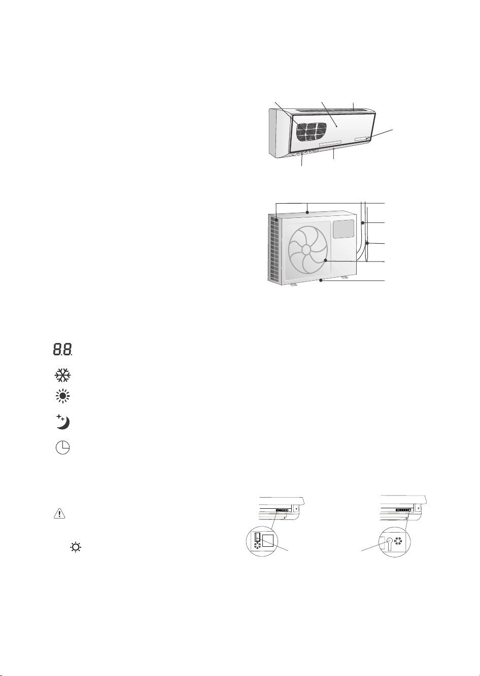
IDENTIFICATION OF PARTS
1. Outdoor unit and Indoor unit
1. Filter
2. Front Panel
3. Air inlet
4. Display
5. Deflector
6. Left / Right deflector (Manual operation)
Outdoor unit
7. Air inlet
8. Connecting pipe
9. Drain hose
10. Air outlet
11. Drain opening
The figure above is only a simple presentation of the unit, it may not match the external appearance of the
unit you purchased.
2. Display Indicators
Temperature indicator
Displays set or room temperature.
COOL MODE indicator lamp
HEAT MODE indicator lamp
Sleep indicator
It lights up during sleep mode.
Timer indicator lamp
If the batteries in the remote control are flat, or the remote control is faulty, use the Emergency operation
switch.
3. Emergency Operation switch
The places of e different models maybe
different, but all of the emergency operation switch
of emergency operation switches are shown by the
icon .
• Cooling only mode
Every time the switch is pressed, it changes in sequence from COOL → STOP.
• Heat pump mode
Every time the switch is pressed, it changes in sequence from COOL → HEAT → STOP.
Emergency
Operation switch
q
w
y
e
r
t
u
i
o
a
s
7
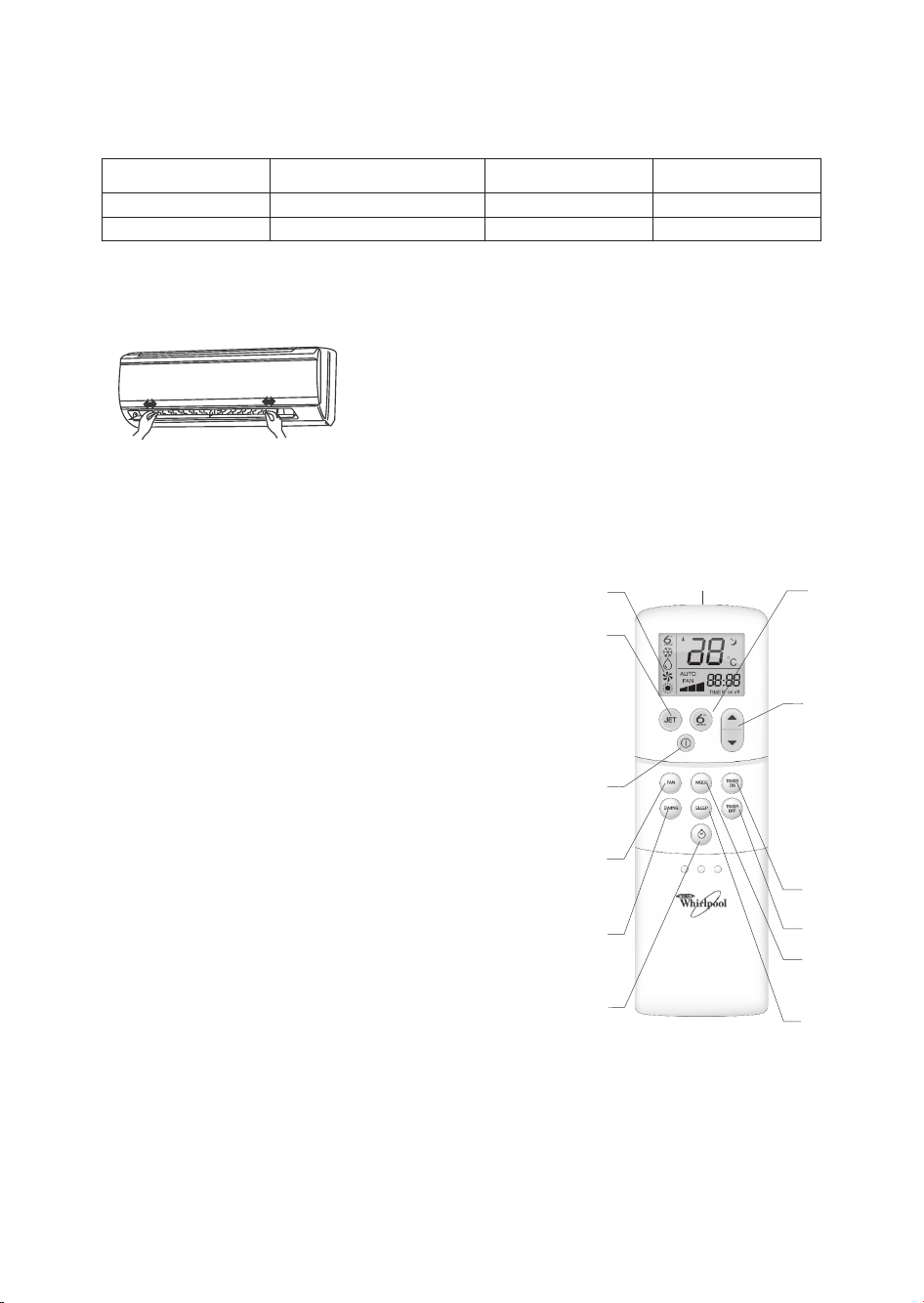
The following table shows the set temperature, fan speed and deflector values during emergency operation.
Hold the knob and move the deflector to change right/left airflow direction. Never attempt to adjust the
deflector during operation as the fan rotates at very high speed and may injure your fingers.
4. Horizontal Louver
Mode Set temperature Fan speed Deflector
Cooling 24 °C High Swing
Heating 24 °C High Swing
A. Signal window: The signal is sent to the indoor unit.
B. OPERATION DISPLAY: It displays the current settings.
C. JET button: Used to activate rapid cooling.
D. ON/OFF button: When this button is pressed, the appliance starts
if it is powered up or stops if it is already running.
E. FAN button: Press this button to change the fan speed of the
indoor unit in the order of Low - Medium - High - Auto.
F. SWING button: Used to stop or start vertical adjustment louver
swinging and set the desired up/down airflow direction.
G. CLOCK button: Please see "Timer operation".
H. 6TH SENSE button: Used to enter fuzzy logic smart operation
I. TEMPERATURE ADJUSTMENT buttons: Used to set time in
TIMER on/off mode and REAL TIME CLOCK. Every press of the
button increases the setting temperature by 1°C. And the highest
setting temperature is 31°C. Every press of the button decreases
the setting temperature by 1°C. And the lowest setting
temperature is 16°C.
J. TIMER ON button: Please see "Timer operation".
K. TIMER OFF button: Please see "Timer operation".
L. MODE button: Press this button to change the operation mode in
the order of Cool - Dry - Heat - Fan.
M. SLEEP button: Used to set or cancel Sleep Mode operation.
NOTE:
• Keep the remote controller within 6 metres in front of the indoor unit without any obstructions.
• If the air conditioner is not used for a long time, remove the batteries.
• In this illustration, each section is shown with all the displays on for the purpose of explanation. Some
models may not feature all displays.
• Never tear the batteries open or expose them to naked flames, since this can lead to explosion.
B
F
I
G
D
E
J
C
H
K
L
M
A
REMOTE CONTROL FUNCTIONS
AND INDICATORS
8
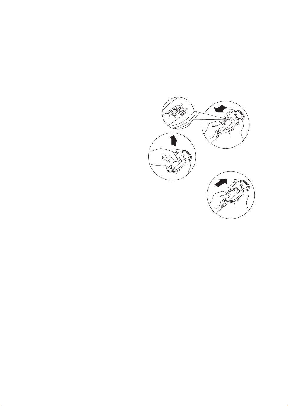
STORAGE AND TIPS FOR USING THE RC
How to Insert the Batteries
Remove the battery cover in the direction of the
arrow.
Insert new batteries making sure that the (+) and
(-) of battery are matched correctly.
Refit the cover by sliding it back into position.
Note:
• Use 2 LR03 AAA (1.5volt) batteries. Do not use
rechargeable batteries.
Replace batteries with new ones of the same
type when the display becomes dim.
• If the replacement is done within 1 minute, the
remote control will keep original presetting.
However, if you replace batteries taking more
than 3 minutes, all presetting will be cancelled
and timer will display Zero.
How to remove the batteries
Remove the battery cover in the direction of the
arrow.
Press the positive pole of the battery softly with
your fingers, then draw the batteries out of the
compartment.
All this should be done by adults, children are
forbidden to remove the batteries from the
remote control in order to avoid danger of
swallow.
Disposal of the batteries
Please discard the batteries as sorted municipal
waste at the accessible collection point.

9
OPERATING MODE DESCRIPTION
AUTO restart
• The same mode/ fan speed/set temperature/swing angle as prior to the power cut are restored.
COOL mode
• Press SWING button to change up/down air flow direction.
Press FAN button to change the fan speed of the indoor unit.
Press the TEMPERATURE ADJUSTMENT button to change the temperature setting.
DRY mode
• Indoor fan motor control
In Dry mode, the fan motor runs at low speed.
When the compressor switches off, the indoor fan continues running.
• In Dry mode, the temperature settings remain the same, but 2°C lower than the previous temperature.
• Compressor control
When the room temperature is below 16°C, the compressor is off.
When it is over 16°C, the compressor runs intermittently, with operation periods depends on the
temperature setting and the room temperature.
When the room temperature is over or equal to 23 °C, the compressor runs for 8 mins and remains off
for 3 mins.
When the room temperature is below 23, the compressor runs for 2 mins and remains off for 3 mins.
When the room temperature is lower than the set temperature, the compressor runs for 1 min and
remains off for 4 mins.
FAN mode
• In this mode, the indoor unit operates like a fan only.
When the fan speed is set to Auto, the fan speed is low.
Press SWING button to change up/down air flow direction.
Press FAN button to change the fan speed from Low-Med.-High of the indoor unit.
HEAT mode (heat pump type)
• Press SWING button to change up/down air flow direction.
Press FAN button to change the fan speed of the indoor unit.
Press ROOM TEMPERATURE ADJUSTMENT button to change the temperature setting.
SLEEP mode
• When this button is pressed, the fan speed is low. In sleep mode, the temperature setting increases (in
cooling mode) by 1°C or decreases (in heating mode) by 2°C per hour automatically. After 2 hours, the
temperature setting remains at the user temperature setting +2°C (in cooling mode) and -4°C (in
heating mode). When the room temperature is lower (in cooling mode) or higher (in heating mode)
than the set temperature, the compressor stops until the room temperature is higher (in cooling mode)
or lower (in heating mode) than the set temperature.
DEFROST
A.Defrosting is activated: in the presence of both of the conditions listed below.
• When the compressor has been running for 40 mins;
• The temperature of the outdoor pipe OPT ≤ -4°C and has been running for 1min.
B. Defrosting is ended: in the presence of one of the conditions listed below.
• The temperature of outdoor pipe OPT ≥ 15°C and has been running for 1min.
• Defrosting has been active for over 10 mins.
JET mode
Used to activate rapid cooling. Rapid cooling operates at high fan speed with 16°C as automatic set
temperature. If you press the on/off button when the appliance is running, it will be stopped. When the
room temperature is lower than the set temperature (16°C), the compressor stops, fan speed remains
high.

10
6TH SENSE mode
Used to enter fuzzy logic operation directly.
Timer operation
Preparation Before Operation
• Open the cover and insert two new batteries.
• Press the clock button: the time in hours and minutes will flash on the display, press to adjust the hours
and press to adjust the minutes. Press the button again, and the time will be set.
• Close the cover.
TIMER ON/OFF
(When user presses on/off on the remote controller, all the setting reports of time on/off will be
cancelled.)
A. TIMER ON
Press this button to switch the remote controller and air conditioner to timer-on mode. "Timer on" is
shown on the LCD display. Time can be set from 1H to 24H, with one hour increments each time the
button is pressed.
The timer can be set on a daily basis only.
B. TIMER OFF
When the remote controller is on, press this button to switch the remote controller and air
conditioner to timer-on mode. "Timer-off" is shown on the LCD display. Time can be set from 1H to
24H, with one hour increments each time the button is pressed.
C. COMBINATION OF TIMER ON AND OFF
• When the unit and the remote controller are on, press the timer-off button to switch the remote
controller and air conditioner to timer-off mode. Timer-off is shown on the LCD display. Time can
be set from 1H to 24H, with one hour increments each time the button is pressed.
Next, press the timer-on button to switch the remote controller and air conditioner to timer-on
mode. Timer-on is shown on the LCD display. Time can be set from 1H to 24H, with one hour
increments each time the button is pressed. (timer off - timer on)
• When the unit and the remote controller are off, press the timer-on button to switch the remote
controller and air conditioner to timer-on mode. Timer-on is shown on the LCD display. Time can
be set from 1H to 24H, with one hour increments each time the button is pressed.
Next, press the timer-off button to switch the remote controller and air conditioner to timer-off
mode. Timer-off is shown on the LCD display. Time can be set from 1H to 24H, with one hour
increments each time the button is pressed (timer on - timer off).
Mode Initial room temperature .A Initial room temperature .B
Cooling
RT ≥ 26°C
24°C
26°C >RT ≥ 25°C
RT-2
Dry
25°C >RT ≥ 23°C
RT-2
Heating RT < 23°C 26°C

11
SERVICE AND MAINTENANCE
Clean the front grille and air filters at least once
every two weeks.
Before cleaning, be sure to switch the appliance
off and turn off the circuit breaker.
In this section, diagrams are for illustration
purposes only.
During operation, please refer to your actual
appliance.
Clean the front grille and air filters
1. Open the front grille by pulling the tabs on both
sides, then lifting up until it stops with a click.
Pull out the air filters.
2. Remove all dust on the front grille and air filters
with a vacuum cleaner or brush. (If the dust does
not come off easily, wash them with neutral
detergent dissolved in warm water - max.
temperature 45°C)
3. Rinse in clean water and dry in the shade.
4. Insert the front grille and air filters in their original
position and close the front grille.
5. Wipe the surface of the unit with a neutral
detergent and then wipe it again with dry cloth.
(Be sure not to use benzene, solvent or other
chemical products.)
In the event of prolonged disuse
1. Switch the fan on for a few hours to dry out the
inside thoroughly. (Choose COOL mode or HEAT
mode and select the highest temperature setting,
then switch the fan on.)
2. Switch the air conditioner off. Clean the filters and
the outside of the unit.
3. Remove the batteries from the remote control.
If you have not used the air conditioner for a
prolonged period of time
1. Clean the filters and return them to the original
position. Clean the indoor and outdoor units with a
soft cloth.
2. Insert the power plug and make sure the earth wire
is not loose.
3. Put the batteries in the remote controller.
NOTE:
• Air inlets and outlets must not be covered/blocked.
• For cleaning, never use petrol, benzene, thinner,
grinding powder, detergent insecticide etc as they
could damage the units.
• Never tear the batteries open or expose them to
naked flames, since this can lead to explosion.

12
Operation problems are often due to minor causes that can be found and fixed without
using any tools:
If you find any of the following symptoms, please turn the circuit breaker off immediately
and call the authorized service centre nearest to you for help.
• The power supply cable is abnormally hot or damaged.
• The appliance makes abnormal sounds during operation.
• The safety breaker, fuse or earth leakage breaker often cuts off operation.
• Some switch or button repeatedly fails to work normally.
• The air conditioner produces a burning smell during operation.
• Water leaks from the indoor unit.
TROUBLESHOOTING
Trouble Analysis
Does not run
• Is the protection device or fuse blown?
• Please wait for 3 minutes and start again, protection device may be
preventing unit to work.
• Are the RC batteries low?
• Is the plug not properly plugged?
No cooling or heating air
• Is the air filter dirty?
• Are the intakes and outlets of the air conditioner blocked?
• Is the temperature set properly?
Ineffective control
• Has there been a strong interference (from excessive static electricity
discharge, power supply voltage abnormality)? Note that operation will
be abnormal, in this case unplug from the power supply and re-plug after
2-3 seconds.
Does not operate
immediately
• 3 minute delay will occur when changing mode during operation.
Peculiar smell
• This smell may come from another source such as furniture, cigarette
etc, which is sucked in the unit and blown out with the air.
A sound of running water
• Normal behaviour caused by the flow of refrigerant in the air
conditioner.
• Defrosting sound in heating mode.
Cracking sound
• The sound may be generated by the expansion or contraction of the
front panel due to temperature changes.
Mist sprays from the outlet
• Mist is present in the room with low temperature? Normal behaviour
due to cool air discharged from indoor unit during COOLING or DRY
operation mode.
After switching off, the flap
appears not to close fully.
• The stepping motor could not find the RESET point. Restart the air
conditioner and then stop it again.
Indoor unit fan stops during
heating.
• The air conditioner is de-icing, which takes 10 minutes at most. (It
freezes when the outdoor temperature is very low and humidity is high).
It automatically resumes operation after approximately 10 minutes.

13
Attention:
The allowable length of the connecting pipe is
10m.
The allowable distance between indoor unit and
outdoor unit is 5m.
Confirm the installation position using the marks
on the indoor mounting plate.
Note: Different models have different
mounting plates, the installing charts of this
book are presented just for the purpose of
illustration, please take the real objects as
reference.
The copper pipe can be installed to the back, right,
underside, or left-back side.
Notice: do not raise the drain hose.
While installing the pipeline on thin armor plate or
wire mesh wall, use a wooden board to clamp
between the wall and the pipeline, or wrap the
pipeline with 7-8 layers of insulating plastic tape.
Cover the connecting pipe with adiabatic material.
NOTICE D’INSTALLATION
above 105mm
back
right
back
underside
left-back
left
front
8mm thick sponge plastic
adiabatic material.
above 155mm
above 250mm
above 20mm
above 500mm
above 300mm
above 500mm
above 500mm
above 300mm
PP
Ϟ
ҹ

14
Location of indoor unit
• Keep the air inlet and outlet at a far distance from the blockage.
• Keep the difference in height between the indoor and outdoor unit to 5m max.
• Mount on a wall that is solid enough to bear the weight of the unit and not cause any shaking.
• Avoid direct sunshine.
• Choose a location that allows for a condensation drain and for connection to the outdoor unit.
• Keep far away from fluorescent lamps, which may have a negative affect on remote controller
operation.
• Keep at least 1meter away from TV, radio and other home appliances.
Location of outdoor unit
• Choose a location sturdy enough to bear the weight of the unit and not cause any shaking.
• Ensure there is adequate, little dust, and protection from direct rain and sunshine.
• Choose a location where the air discharged from the outdoor unit and appliance operating noise will
not annoy your neighbours.
• Ensure there is no blockage near the outdoor unit.
• Avoid places close to potential flammable gas leakage.
INSTALLATION OF THE INDOOR UNIT
Secure the mounting plate
The mounting plate should be attached to the
structural part of wall (post etc).
NOTICE:
• The holes at solid arrow position must be secured
to avoid the shake of mounting plate.
• When the expansion bolts are used, two holes (
11×20 or 11×26 ) that the distance between them
is 450mm should be adopted.
Drill on the wall
Operation:
1. Confirm the position of the wall hole according to
the chart (If it need to orientat a hole on the left
side of the mounting plate, please refer to the
method of orientating the right wall hole in the
above chart.
2. Use the aiguille to drill a hole with a diameter of
65mm.
NOTE:
• Secure all holes drilled at solid arrow positions to
prevent the mounting plate shaking.
• When expansion bolts are used, use two holes
(11x20 or 11x26) with a distance of 450mm
between them.
• Check the position of the holes, then drill.
Wiring
• Open the front grille.
• Unscrew the electrical box cover, remove the cover
from the unit and set aside.
• Unscrew the fastener, remove the fastener from the
unit and set aside.
• Connect the cable.
• Replace the fastener and electrical box cover.
fasten string at the central hole
105mm or more
from sidewall
Tapping
screw
ST4×25(5)
mounting
plate
plumb
at least 250mm
155mm or more
from sidewall
Center of hole (Ø 65mm)
Pipe hole
Center of hole
(Ø 65mm)
Diagram
Screw
Indoor unit terminal
Connecting cable

15
NOTE:
• The appliance must be installed in accordance with national wiring regulations.
• The appliance must not be installed in a laundry area.
• The appliance must be installed at a height of 2.3m above the floor.
• The appliance must be positioned so that the plug is accessible.
• For selected models with a cooling capacity above 4600W (17000BTU/h), an all-pole disconnect switch
with contact gap of at least 3mm must be fitted in the fixed wiring in accordance with national
regulations.
Installation of the drain hose
NOTE:
• The drain hose must be positioned beneath the
copper pipe.
• The drain hose must not be kinked or twisted.
• While insulating the drain hose, do not pull it.
• The section of the drain hose that passes through
the wall must be thermally insulated.
• The copper pipe and the drain hose must be lagged
using felt strip. Adiabatic pads must be used where
the pipe passes through the wall.
ROUTE OF PIPE
If the pipe comes out on the right side of the indoor
unit, cut part "1" of the unit.
If pipe comes out on the lower-right side of the indoor
unit, cut part "2" of the unit.
If pipe comes out on the left side of the indoor unit,
cut part 3 of the unit.
REPOSITIONING THE DRAIN HOSE
If the pipe comes out on the left side of the indoor
unit, the drain hose must be repositioned, otherwise
water may leak from the unit.
Repositioning procedure: Invert the position of drain
hose and drain rubber plug.
Clearance is not allowed after repositioning, as it
would result in leaking.
Installation of the indoor unit
Pass the pipe through the hole in the wall and attach
the indoor unit to the mounting plate (press the tab on
the indoor unit into the hook on the mounting plate.)
Liquid pipe
gas pipe
Adiabatic
underlay
Drain hose
felt
drain hose
Drain rubber plug
Indoor unit
the mounting
plate
Bottom
the tab of
indoor unit

16
Pipe Connection
• The number of bends in the pipe in the indoor unit must
not exceed 10.
• The number of bends in the pipe in the indoor unit and
outdoor unit taken together must not exceed 15.
• The radius of the bends must be more than 10cm.
• Snap the evaporator craft tube with pliers before
connecting. After expelling the air inside, use a wrench to
twist down the bottom nut of the connecting tube of the
evaporator.
• Use some airproof oil to cover the joint and the
expanding orifice of the connecting pipe.
• Align the centre of the joint with that of the expanding orifice and tighten the nut of the connecting pipe
using a wrench.
Attention:
Do not expel the air simply by loosening the nut since the air contained in the inside unit is pressurized. Do
not over tighten since there is a risk of damaging the expansion orifice.
Arrangement of the drain hose
• To drain the condensation water easily, the drain hose should be angled downwards.
The following 5 arrangement methods are incorrect.
• If you find the drain hose is not long enough to connect to the indoor
unit, you can extend it with the hoses in the accessory box.
• The section of the drain hose that passes through the wall must be lagged
with special adiabatic material.
Wall sealing and Pipe fastening
• Use putty to seal the hole in the wall.
• Use a clamp (pipe fastener) to secure the pipe in the specified position.
evaporator
craft tube
DIAMETER OF PIPE TORQUE (N • m)
6.35mm (1/4") 12.0-15.0
9.52mm (3/8") 33.0-36.0
12.7mm (1/2") 40.0-45.0
15.88mm (5/8") 73.0-78.0
Angled
downward
Angled
downward
Wate r
leak
Wate r
leak
Standing
water
Wate r
leak
Dip hose
into water
50mm or less
above floor
Drain hose
Hose (ID 15cm)
PVC hard
indoor unit
seal with putty
secure the connecting
pipe with clamp
get rid off unwanted part
clamp
screw

17
INSTALLATION OF THE OUTDOOR UNIT
Wiring
Wiring For Above 6000W Model (Above 21000BTU/h Model)
1. Remove the self-tapping screws (2 pcs) on the
maintenance board and take out the maintenance
board.
2. Loosen the self-tapping screws (2 pcs) on the fixing
clip to loosen the fixing clip.
3. Loosen the fixing screw of the wire terminal board,
pass the power wire and signal wire through the
fixing clip. Then firmly fix the power wire and signal
wire on the terminal board with the fixing screw.
(Earth wire must be connected firmly.)
The cable wire can be led from the back hole of the
piping hole or ejecting hole.
Please utilize outdoor pipe support when the cable
wire is led from the backside.
4. Tighten the self-tapping screw on the fixing clip.
5. Install the maintenance board. After the pipes and
cable wire are installed, please seal the sponge
block as per drawing indication.
Outdoor unit terminal
Connecting cable
Maintenance
board
Terminal board
Fix the cable
wire with
anchor cable
Piping cover
Outdoor pipe support (Outdoor pipe
support is not required when leading the
cable wire from other places).
Maintenance
board
Back wiring
Right wiring
Ejecting hole
Piping cover
Sponge
Piping cover

18
Connect diagram
1500-4600W Model (5000-12000BTU/h Model)
5000-5100W Model (17000-18000BTU/h Model)
6000-7000W Model (21000-24000BTU/h Model)
NOTE:
• If you find the colour of the connecting cable differs from the diagram on the previous page, refer to
actual model.
In any case, the terminal with the same sign must be connected to the connecting cable with the same
color.
• If signal cable must be purchased separately, choose electric cable above 0.75mm.
• If the interconnection cable for the power supply has to be replaced, please refer to the following table.
• The plug housing 1 is connected to the matched receptacle housing of the indoor unit.
• The plug housing 2 is connected to the matched receptacle housing of the outdoor unit.
Brown
Blue
Indoor unit terminal
Connecting
cable
Yellow/Green
Outdoor unit terminal
Cool only type
Brown
Blue
Black
Heat pump type
Plug housing 1
Yellow/Green
Gray
Brown
Blue
Heat pump typeor
Indoor unit terminal
Connecting
cable
Blue
Brown
Yellow/Green
Gray
Black
Brown
Blue
Outdoor unit terminal
Plug housing 1
Plug housing 2
Cool only type
Indoor unit terminal
Connecting
cable
Yellow/Green
Outdoor unit terminal
Brown
Blue
Blue
Brown
Black
Heat pump type Heat pump type Heat pump typeoror
Plug housing 1
Brown
Blue
Yellow/Green
Plug housing 2
Gray
Connecting
cable
Plug housing 1
Indoor unit
terminal
Plug
housing 2
Outdoor unit terminal
Brown
Brown
Blue
Plug housing 1
Yellow/Green
Blue
Blue
Brown
Cool only type
Heat pump type
Heat pump type
or
Brown
Black
Indoor unit
terminal
Blue
Yellow/Green
Outdoor unit
terminal
Connecting cable
Brown
Blue
Yellow/Green
Brown
Blue
Gray
Brown
Black
Yellow/Green
Connecting cable
Plug housing 1
Indoor unit terminal
Blue
Brown
Gray
Outdoor unit
terminal
Plug housing 2
Black
Brown
Connecting cable
Plug housing 1
Black
Brown
Blue
Brown
Blue
POWER
SOURCE
Outdoor
unit terminal
Brown
Blue
Yellow/Green
Connecting cable
Indoor unit
terminal
Brown
Yellow/Green
Blue
Brown
POWER
SOURCE
Blue
Black
Gray
Plug
housing 1
Cool only type (T3) Heat pump type (T3)
Blue
Brown
1
1
5
5
1
1
1
1
1
1
1
1
1
1
1
1
5
5
R2
R1
/
1
/
/
/
1
/
1
/
/
1
/
//
R2
R1
1
/
Y
1
/
1
/
/
1
/
//
N N
L L
/
/
1
1

19
WARNING:
• The electric circuit diagram given on the indoor/outdoor units must be taken as the main reference for
installation.
• The power wires and signal wires between the indoor/outdoor units must be connected one by one as
per corresponding number on the wiring terminal board.
• The connecting cables must be clipped together.
• Special cable must be used to connect indoor unit and outdoor unit. It should be ensured that the
terminals are not influenced by external force. Poor connection may cause fire.
• The electric box cover must be mounted and secured in position, otherwise fire or electrical shock may
occur because of dust or moisture.
• All models must be connected to mains power with system impedance limitations.
• While installing the unit, please see the following table for impedance information or contact the utility
company.
Installation of the drain joint (only for heat pump
type)
• Insert the outdoor double-channel drain joint in one of
the bottom holes of the right size then connect the drain
hose and joint together.
Connecting pipe joint
• Use some airproof oil to cover the joint and the expanding orifice of the connecting pipe.
• Align the centre of the joint with that of the expanding orifice and tighten the nut of the connecting pipe
with a wrench. (Adjust the torque using the same method used for connecting the pipe for the indoor
unit.)
MODEL SPECS (Interconnection cable)
≤ 2700W(10000BTU/h) ≥ 1.0mm²
3200W(11000BTU/h) - 4000W(15000BTU/h)
≥ 1.5mm²
4500W(16000BTU/h) - 8000W(28000BTU/h)
≥ 2.5mm²
8500W(29000BTU/h) - 9500W(32000BTU/h)
≥ 4.0mm²
10000W(34000BTU/h) - 11000W(38000BTU/h)
≥ 6.0mm²
SERIES MODEL IMPEDANCE
R410A series
6800W (24000BTU/h)
≤ 0.124 Ω
5100W (18000BTU/h)
≤ 0.268 Ω
3500W (12000BTU/h)
≤ 0.313 Ω
2500W (9000BTU/h)
≤ 0.409 Ω
Bottom
Double-channel
drain joint
Drain hose

20
Expelling air
• Screw down the cap of both the gas shut-off valve
and the liquid shut-off valve as well as the nut of the
service port.
• Use an Allen wrench to turn the liquid shut-off valve
90° counterclockwise, and close it again after 10
seconds.
• Use soapy water to check for gas leakage, especially
at all joints. If there is no gas leakage, turn the liquid
shut-off valve 90° counter-clockwise again.
• Press the cork of the service port at the gas shut-off
valve. After 10 seconds, a foggy gas is discharged,
meaning the air inside has been expelled.
• Use an Allen wrench to turn both the liquid shut-off
valve and the gas shutoff valve counter-clockwise
until they are fully open and then replace the valve
caps and tighten them.
Expansion of the pipe orifice
• Use a pipe cutter to cut off the broken pipe orifice.
• Remove burrs at the cut of the pipe orifice.
• Insert a nut into the pipe and expand the orifice
with specified tools, reamers for example.
• Check the quality of expanding technique.
Adding refrigerant
• If the connecting pipe is longer than 7 metres, add refrigerant as needed. (Cool only type) added
amount A=(Lm-7m) x 15g/m; (Heat pump type) added amount A= (Lm-7m) x 50g/m. (A: amount of
added refrigerant, L: the length of connecting pipe)
liquid
connecting pipe
allen wrench
gas
connection
pipe
valve
nuts
service port
service port cap
gas shut-off valve
liquid shut-off valve
Copper pipe
Oblique
Roughness Burr
Burr
Reamer
Outer diameter A (mm)
6.35mm (1/4") 2.0-2.5
9.52mm (3/8") 3.0-3.5
12.7mm (1/2") 3.5-4.0
15.88mm (5/8") 4.0-4.5
The length of connecting pipe (m) 7 8 9 10
(Cool only type) added amount (g) 0 15 30 45
(Heat pump type) added amount (g) 0 50 100 150

21
• Expel the air following the above-mentioned
method.
• Close the gas shut-off valve, connect the charging
hose (low pressure) to the service valve and then
open the gas shut-off valve again.
• Connect the refrigerant bottle to the charging hose
and then convert it.
• Add the liquid refrigerant as stated in the above
table.
• Disconnect the manifold gauge after turning off the
shut-off valve, and then open the gas shut-off valve
again.
• Tighten the nuts and caps of each valve.
Operation test
• Before testing operation, carefully inspect the wiring again and make sure it is safe.
1. Emergency switch operation: Every time the emergency switch is pressed, the air conditioner runs in
the following order:
Cool only type: Cool → Shut off
Heat pump type: Cool → Heat → Shut off
2. Remote control operation: If the indoor unit beeps when the I/O button is pressed, this indicates the air
conditioner is being operated with the remote control. After that, press every button to test operation.
3. Check switch operation: open the front grille and press the check button. Switch on the power source
to activate the operation test. If the indicator lamps light up first and then go out in succession, the
system is operating normally. If one of the indicator lamps flashes at all times, there is a system
malfunction. Consult the troubleshooting guide immediately.
Pressure meter
High pressure valve
Charging line
Service port
Low pressure valve
Manifold gauge
 Loading...