

Whirlpool AKR 009/IX, AKR 009/WH, AKR 001/IX, AKR 013/IX, AKR 002/IX INSTRUCTION FOR USE
...
N C
INTRODUCTION
BEFORE USING THE COOKTOP
1. Clean the cooktop.
2. Light the burners to remove fumes and smells from the protective greases.
FOR EVERYDAY USE
1. Turn the control knob to the “large flame” position
2. Operate the electric ignition (see the model specifications)
3. In the models with safety valves keep the knob pressed for 10 seconds after the burner has lit.
4. To turn off turn the knob to “
Read the Instructions For Use carefully so that you become familiar with your cooktop.
26
M Y
26
x”.

N C
TABLE OF CONTENTS GB
FEATURES page 28-29-30
BEFORE USING THE COOKTOP page 31
TIPS FOR SAFEGUARDING THE ENVIRONMENT page 31
WARNINGS FOR THE USE OF ELECTRICAL APPLIANCES page 32
PRECAUTIONS AND GENERAL SUGGESTIONS page 32
GAS COOKTOP page 33
USING THE COOKTOP page 35
CLEANING AND MAINTENANCE page 36
TROUBLE-SHOOTING GUIDE page 37
AFTER-SALES SERVICE page 37
INSTALLATION page 38
27
M Y
27
N C
FEATURES
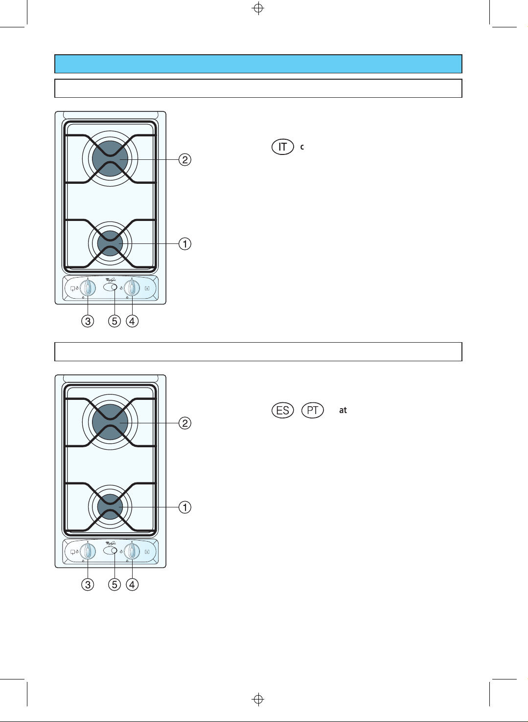
AKR 001
2 GAS COOKTOP
- This appliance is Class 3.
cat. III 1a2H3+.
o
GAS BURNERS
1. Medium-power burner - 1.65 kW
2. High-power burner - 3.00 kW
CONTROL PANEL
3. Front burner control knob (1)
4. Rear burner control knob (2)
5. Electric ignition push-button
Note:
The appliance is fitted with a safety valve on each
burner which shuts off the gas supply if the gas goes
out accidentally.
AKR 002
2 GAS COOKTOP
- This appliance is Class 3.
kv
GAS BURNERS
1. Medium-power burner - 1.65 kW
2. High-power burner - 3.00 kW
CONTROL PANEL
3. Front burner control knob (1)
4. Rear burner control knob (2)
5. Electric ignition push-button
cat. II 2H 3+.
28
M Y
28

N C
AKR 009
2 GAS COOKTOP
- This appliance is Class 3.
cat. II 2E+ 3+.
l
GAS BURNERS
1. Medium-power burner - 1.65 kW
2. High-power burner - 3.00 kW
CONTROL PANEL
3. Front burner control knob (1)
4. Rear burner control knob (2)
5. Electric ignition push-button
AKR 013
2 GAS COOKTOP
- This appliance is Class 3.
m
GAS BURNERS
1. Medium-power burner - 1.65 kW
2. High-power burner - 3.00 kW
CONTROL PANEL
3. Front burner control knob (1)
4. Rear burner control knob (2)
5. Electric ignition push-button
Note:
The appliance is fitted with a safety valve on each
burner which shuts off the gas supply if the gas goes
out accidentally.
cat. II 2ELL 3B/P.
29
M Y
29
N C
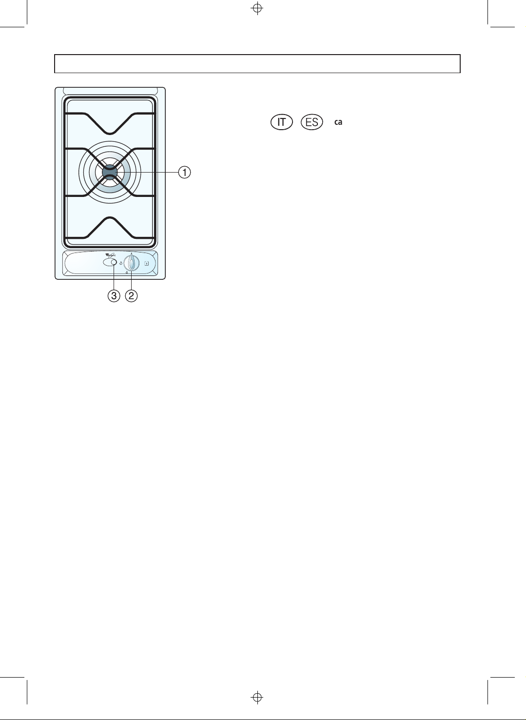
AKR 003
DOUBLE CROWN GAS COOKTOP
- This appliance is Class 3.
ok
cat II 2H3+.
GAS BURNERS
1. Double-crown burner - 3.30 kW
CONTROL PANEL
2 Double crown burner control knob
3. Ignition push-button
Note:
The appliance is fitted with a safety valve on each
burner which shuts off the gas supply if the gas goes
out accidentally.
30
M Y
30
N C
BEFORE USING THE COOKTOP
x
For best use of your cooktop, read the
Instructions For Use carefully and keep them in
asafeplace.
x
This appliance must only be used for the
purpose for which it was designed, i.e. for
cooking foods.
Any other use should be considered incorrect
and therefore dangerous.
x
The manufacturer declines all responsibility for
damage caused by unreasonable, incorrect or
contrary to these instructions.
x
Do not try to alter the technical features of
the appliance, because this could be very
dangerous.
x
Packaging materials (plastic bags, polystyrene pieces,
etc...) must be stored out of the reach of children as
they are potentially dangerous.
x
Check that the cooktop has not been damaged
during transport. If in doubt, consult a specialised
engineer.
x
Please make sure that the installation and
electrical connections are made by a qualified
electrician following the manufacturer’s
instructions and in compliance with the local
regulations in force.
TIPS FOR SAFEGUARDING THE ENVIRONMENT
1. Packaging
The packaging material is 100% recyclable and is
marked with the recycling symbol
type of material which must be taken to the local
collection centres.
to identify the
Ù
2. Product
The cooktop has been manufactured with recyclable
material. Dispose of it following the local regulations
for the disposal of waste.
Before disposing of it make it unusable by cutting
off the supply cable.
31
M Y
31
N C
WARNINGS FOR THE USE OF ELECTRICAL APPLIANCES
When using electrical appliances some
important rules must always be followed. In
particular:
x
Never touch the appliance with wet or damp hands
or feet
x
Never use the appliance with bare feet
x
Keep children away from the hob when it is in use.
x
Before any cleaning or maintenance, switch off the
electricity to the cooktop.
PRECAUTIONS AND GENERAL SUGGESTIONS
x
Risk of fire!
Do not leave inflammable material on the cooktop.
x
Make sure that the electrical cables of other
appliances installed near the cooktop do not come
into contact with it.
x
During and immediately after operation some parts
of the cooktop reach very high temperatures. Do
not touch them.
x
Keep children away from the appliance, especially
when it is being used.
x
After using the cooktop make sure that the knobs
are switched off.
x
When not using the cooktop it is a good idea to
switch off the gas line supply tap.
EU Declaration of conformity
x
This cooktop is intended to come into contact with
food products and conforms with European
Directive 89/109/EEC.
x
This cooktop has been designed, constructed and
put on to the market in conformity with:
- Safety requirements of the “Gas” Directive 90/
396/EEC and amendments;
- Safety requirements of the “Low Voltage”
Directive 73/23/EEC and amendments;
- Protection requirements of the “EMC” Directive
89/336/EEC and amendments;
- Requirements of Directive 93/68/EEC.
n
If the cooktop is fitted with a glass cover:
x
Do not close the glass cover when the hotplates are
still hot. If there is an oven under the cooktop, do
not close the cover when the oven is switched on
or still hot.
x
Do not put pans or heavy objects on the cover.
x
Dry off any liquid which may have spilt on the cover
before opening it.
32
M Y
32

N C
GAS COOKTOP
AKR 001 – AKR 003 – AKR 013
GAS BURNERS
The flow of gas to the burners is adjusted by the
knobs which control the taps with safety valves.
Match the mark on the knob with the symbols printed
on the panel:
-fulldisc
- symbol
- symbol
x
=tapoff
= max. opening or max. flow
æ
æ
= min. opening or min. flow
To light one of the burners:
1. Press and turn the gas tap knob anticlockwise to the
maximum flow position, press it down and keep it
pressed.
2. Press the electric ignition push-button. If there is a
power cut use a flame.
3. Wait for ten seconds after lighting the burner before
releasing the knob (valve triggering time).
4. Set the gas tap to the position required.
If particular characteristics of the locally supplied gas
make lighting the burner with the knob in the
maximum flow position difficult, repeat the operation
with the knob in the minimum flow position.
If the burner flame should go out for any reason, the
safety valve will automatically shut off the gas supply.
To light the gas again, turn the knob to the
and then repeat the lighting operations.
The maximum flow is used to bring liquids to the boil
quickly, while the low flow is used to heat food slowly
or for simmering.
All the operating positions must be chosen between
the maximum and the minimum and never between
the maximum and the OFF.
x
position
33
M Y
33

N C
GAS COOKTOP
AKR 002 – AKR 009
GAS BURNERS
The flow of gas to the burners is adjusted by the
knobs which control the safety-closing taps.
Match the mark on the knob with the symbols printed
on the panel:
-fulldisc
x
=tapoff
- symbol
- symbol
To light one of the burners:
1. Press and turn the corresponding knob to the
maximum flow position (large flame).
2. Press the electric ignition push-button until the gas
has lit. If there is a power cut use a flame.
3. Set the gas tap to the position required.
If particular characteristics of the locally supplied gas
make lighting the burner with the knob in the
maximum flow position difficult, repeat the operation
with the knob in the minimum flow position.
The maximum flow is used to bring liquids to the boil
quickly, while the low flow is used to heat food slowly
or for simmering.
All the operating positions must be chosen between
the maximum and the minimum and never between
the maximum and the OFF.
= max. opening or max. flow
æ
æ
= min. opening or min. flow
34
M Y
34

N C
USING THE COOKTOP
SPECIAL GRIDS FOR WOKS
optional (only model AKR 003)
This special grid for woks rests on the grid of the
double-crown burner.
WARNING:
− Using woks without this special grid could seriously
damage the burner.
− Donotusethisgridwithflatbottomedpans.
ENERGY SAVING HINTS
x
Use pans with base of the same diameter or slightly
larger than that of the cooking zone.
x
Use only flat-bottomed pans.
The use of pans with concave or convex bottoms is
not recommended.
x
The pans must not interfere with the control panel.
x
If possible, put covers on pans.
x
Boil vegetables, potatoes, etc. with just a little water
to save energy.
x
Pressure cookers help to save energy and are
quicker than traditional pans.
PAN DIAMETER
Burners minimum maximum
Medium-power 16 cm 22 cm
High-power 24 cm 26 cm
Doublecrown 24cm 28cm
WOKdiametermax.36cm
Warning: During use the cooktop cooking
zones become very hot. Keep children away.
35
M Y
35

N C
CLEANING AND MAINTENANCE
CLEANING THE COOKTOP AND
CONTROL PANEL
x
Before cleaning the cooktop switch it off and wait
forittocooldown.
x
Cleanwithaclothwettedwithhotwaterandsoap
or water and liquid detergent.
x
Do not use products which are abrasive, corrosive or
chlorine based, or steel pads.
x
Do not leave acid or alkaline substances (vinegar,
salt, lemon juice etc.) on the cooktop.
ENAMEL COOKTOP
x
Enamelled parts must be washed using a sponge,
with soapy water or other non-abrasive products.
Drywithasoftcloth.Ifacidsubstancessuchas
lemon juice, tomato conserve, vinegar etc. are left
on the enamel for a long time they will etch it,
making it opaque.
STAINLESS STEEL COOKTOP
x
Stainless steel parts must be rinsed with water and
dried with a soft and clean cloth or with a chamois
leather.
x
For difficult dirt, use a specific non-abrasive product
available commercially or a little hot vinegar.
x
Note: regular use could cause discolouring around
the burners, because of the high temperature.
CLEANING THE BURNERS AND THE
GRIDS
x
These pieces can be removed and washed with
suitable products.
x
After cleaning, the burners and spreaders must be
dried carefully and put back into their housing
correctly.
x
It is very important to check the correct position of
the burner spreader because if it moves out of place
serious problems could occur.
x
In models which have safety valves, make sure that
the sensor, near to each burner, remains clean so
that the safety valves can work properly.
x
In appliances with electric ignition make sure that
the electrode remains clean so that the sparks can
strike properly. The spark plugs must be cleaned
very carefully.
N.B.: To avoid damage to the electric ignition, do
not use it when the burners are not in place.
GAS TAPS
The gas taps should be cleaned regularly and only by
specialised engineers.
If the gas taps are not working correctly, call the AfterSales Service.
36
M Y
36

N C
TROUBLE-SHOOTING GUIDE
1. The burner does not light:
x
Is the gas supply tap switched on?
x
Has the gas supply (methane) been cut off?
x
Is the cylinder empty? (Liquid gas).
x
Are the burner openings clogged?
x
Have the cap or burner been repositioned correctly
after cleaning?
AFTER-SALES SERVICE
Before contacting the After-Sales Service:
1. Check whether you can deal with the problem
yourself (See “Trouble Shooting Guide”).
2. Switch on the appliance again to check whether the
problem has been solved.
3. If it is still not working properly, call the After-Sales
Service.
Give:
x
The type of fault
x
The model
x
The Service number (the number after the word
SERVICE on the rating plate underneath the cooktop,
on the guarantee and on this instruction manual).
x
Your complete address including Post Code
x
Your telephone number
x
When you can be contacted.
2. The burner does not stay lit:
x
Repeat the lighting operation turning the knob to
the symbol representing the small flame
3. The electric ignition does not work:
x
Is there a power failure?
l
æ
.
37
M Y
37
N C
INSTALLATION
x
The installation, adjustment and modification of the
appliance for the use of other gases must be
performed by a trained installer. Failure to observe
this rule will lead to cancellation of the guarantee.
x
The appliance must be installed correctly and in
conformity with the local regulations in force.
x
Any operation must be performed with the
appliance switched off.
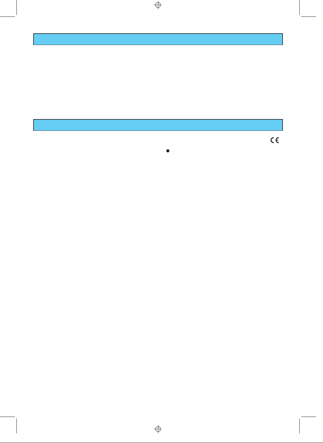
Combustion product
extractor hood
INSTALLATION ROOM
x
In the room where the cooktop is installed there
must be enough air for correct gas combustion (2
3
/h x kW).
m
The installer must refer to the national
standards in force concerning ventilation and
removal of combustion products.
x
The natural flow of air must occur through one or
more suitable openings which must be:
- Permanent and made in the outside walls of the
room to be ventilated, in an area away from
sources of pollution.
- So made that the opening outlets, both inside and
outside the wall, cannot be blocked, even
accidentally.
- Protected with grids, metal net etc. so as not to
reduce the useful section indicated above.
- Situated at roughly floor level and such as not to
cause disturbance to the correct operation of the
combustion product removal devices.
When these openings cannot be made, the necessary
airmustcomefromanadjacentroom,ventilatedas
required, as long as it is not a bedroom or a dangerous
room. In this case the kitchen door must allow the
passage of air.
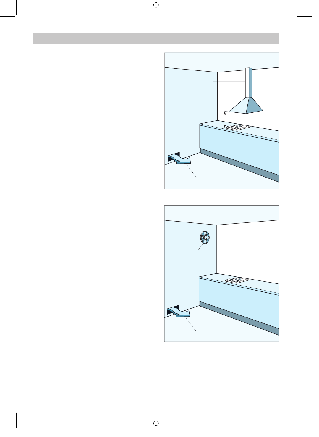
DISCHARGE OF THE COMBUSTION
PRODUCTS
The combustion products of gas appliances must be
discharged through hoods connected directly to the
outside.
When this is not possible an electric fan can be used,
attached to the outside wall or to the window, having
a capacity such as to allow an hourly exchange of air of
3–5timesthevolumeofthekitchen.
The fan can only be installed if there are suitable
openings for the inlet of air.
H min 650 mm
Opening for
air inlet
Electric fan to
remove combustion
products
Opening for
air inlet
38
M Y
38

N C
INSTALLATION
Technical information for the installer
The appliance must be installed by a qualified engineer
following the manufacturer’s instructions and in
compliance with local regulations in force.
To fit the cooktop into the unit remember that:
− inside the unit there must be a space of at least
30 mm between the bottom of the cooktop and
the top of an appliance or bracket.
− any wall to the side and above the cooktop must
be at least 100 mm away.
− the wall behind the cooktop must be at least 50
mm away.
− when there is a wall unit or hood above the
cooktop there must be at least 650 mm between
the cooktop and the unit or hood.
− the coatings of the walls of the unit or appliances
nearthecooktopmustbeheatresistant(“Y”
protection against heating in compliance with
standards EN 60335-2 6).
Do not install the cooktop near inflammable
materials (e.g. curtains).
39
M Y
39

N C
INSTALLATION
Before installing the cooktop, remove the protective
film.
This cooktop can be built into a working surface 20 to
40 mm thick and 600 mm deep.
To fit the cooktop into the unit make a hole of the
dimensions given in the figures below and respect the
indications given in the previous section “Technical
information for the installer”.
AKR 003 AKR 009 - AKR 013
AKR 001 - AKR 002
40
M Y
40

N C
INSTALLATION
INSTALLING SEVERAL DOMINO
COOKTOPS SIDE-BY-SIDE
Several DOMINO cooktops can be installed side-by-side
using the special junction piece (code No. AMH 719)
available from the After-Sales Service.
For this type of installation openings must be made in
the unit as indicated in the figure, remembering that:
− all the provisions described for the single installation
must be observed
− a 5 mm space must be left between the cooktops
to insert the junction piece
− for installations with more than 3 cooktop side-byside calculate the hole needed referring to the
measurements given in the figures.
− each cooktop must have its own gas/electrical
supply
2 DOMINO side-by-side
3 DOMINO side-by-side
AMH 719
850
41
M Y
41

N C
INSTALLATION
INSTALLATION ON UNITS WITH DOOR
The unit must be so constructed that when the door is
opened or closed, even violently, the pressure or
depressure caused by this does not cause the burners
to go out, whether set to minimum or maximum.
Leave a depressure space of 30 mm between the
bottom of the cooktop and the top of the unit
underneath.
30 mm
FASTENING THE COOKTOP
Eachcooktopissuppliedwithasetoftabsandscrews
to fasten it on units with a working surface from 2 to 4
cm deep.
The kit includes 4 tabs “A” and 4 self-threading
screws “B”.
- Cut the unit.
- Stretch gasket “C” over the edge of the hole made,
being careful to overlay the junction edges.
Depressure space
Door
Space for connections
- Turn the cooktop over and put tabs “A” into the
mountings; only tighten screws “B” a few turns.
Make sure that the tabs are mounted correctly as
showninthefigure.
- Put the cooktop into the hole cut into the unit and
position it correctly.
- Put tabs “A” into place and tighten screws “B” until
the cooktop is completely secured.
C
B
A
20 mm min.
40 mm max
42
M Y
42

N C
INSTALLATION
GAS SUPPLY CONNECTION
Thecooktopissetupandcalibratedtoworkwiththe
gas indicated on the rating plate affixed to the
appliance.
The gas supply system must conform to the local
regulations in force.
To connect the cooktop to the gas mains or cylinder
use a flexible stainless steel hose with continuous wall
conforming to local regulations. Use gasket F for the
cylindrical elbow connection.
The flexible metal tubes must be at most 2 m long.
Attention: If a flexible stainless steel hose is used,
it must be so installed that it cannot come into
contact with a movable part of the unit and is
not obstructed and so that its whole length can
be inspected.
The cooktop connection is made up as follows:
− 1 nipple or 1 nut “A”
−1bicone“B”
− union elbow “C”:
- cylindrical – for Italy, France, Spain and Portugal
- conical – for Germany
IMPORTANT:
− Never turn union C forcibly without first
slackening nipple or nut A. In versions with
bicone “A”, use 2 spanners for this operation.
Never leave it in the horizontal or vertical
position.
− Gasket F and bicone B are the elements which
guarantee the gas connection seal.
Replace them when they are even slightly
deformed or imperfect.
− After the connection check the connection seal
with a soapy solution, never with a flame.
conical
cylindrical
43
M Y
43

N C
INSTALLATION
ADAPTATION TO DIFFERENT TYPES
OF GAS
If a gas different from that indicated on the label is
used, adapt the cooktop to this new function.
Each cooktop comes with a set of injectors for the
various types of gas.
Injectors not supplied can be obtained from the AfterSales Service.
Proceed as follows:
1. Replace the injectors with the correct ones.
2. Connect the cooktop to the on-off tap with a tube
which is suitable for the gas to be used according
to the regulations in force.
3. Adjust the gas burner minima.
Replacing gas burner injectors
Choose the injectors to be replaced according to the
tables of Page 45.
The injector diameter, expressed in hundredths of a
millimetre, is marked on the injector bodies.
To replace the injectors proceed as follows:
− Remove the grids and extract the burner bodies
− With a spanner replace nozzles “J” with nozzles
suitable for the gas to be used.
The burners are so designed that there is no
need to adjust the primary air.
44
M Y
44

N C
INSTALLATION
INJECTOR TABLES
o
G30/G31 G20 G110
BURNERS
Medium-power 1,650 0,35 65 94 185
High-power 3,000 0,60 85 128 290
Rated output Low output
[kW] [kW] Ø injector Ø injector Ø injector
28-30/37 mbar 20 mbar 8 mbar
[1/100 mm] [1/100 mm] [1/100 mm]
kvo
G30/G31 G20
BURNERS
Medium-power 1,650 0,35 65 94
High-power 3,000 0,60 85 128
Double-crown 3,300 1,50 92 139
Rated output Low output
[kW] [kW] Ø injector Ø injector
28-30/37 mbar 20 mbar
[1/100 mm] [1/100 mm]
l
G30/G31 G20/G25
BURNERS
Medium-power 1,650 0,35 65 94
High-power 3,000 0,60 85 128
Rated output Low output
[kW] [kW] Ø injector Ø injector
28-30/37 mbar 20/25 mbar
[1/100 mm] [1/100 mm]
cat. III 1a2H3+
cat. II 2H3+
cat. II 2E+ 3+
m
BURNERS
Medium-power 1,650 0,52 58
High-power 3,000 0,85 79
BURNERS
Medium-power 1,650 0,35 94 106
High-power 3,000 0,60 128 138
M Y
Rated output Low output
[kW] [kW] Ø injector
G20 G25
Rated output Low output
[kW] [kW] Ø injector Ø injector
20 mbar 20 mbar
[1/100 mm] [1/100 mm]
cat. II 2ELL 3B/P
G30/G31
50/50 mbar
[1/100 mm]
45
45

N C
INSTALLATION
Adjusting the gas burner minimum
For taps with adjusting screw inside the shaft:
− with a screwdriver, max. diameter 3 mm, turn the
screw inside the tap shaft until adjustment is correct.
− perform the adjustment with the tap in the
minimum position (small flame
For taps with adjusting screw on the body:
− with a screwdriver turn screw “A” until adjustment is
correct.
− in the models with ignition incorporated in the knob
access to screw “A” is through a hole in the
microswitch.
− perform the adjustment with the tap in the
minimum position (small flame
For gas G30/G31 tighten the adjusting screw
completely.
æ
æ
).
).
GAS TAP LUBRICATION
If a gas tap is difficult to turn, disassemble it, clean it
carefully with petrol and spread a little special hightemperature resistant grease on it.
These operations should be performed by a specialised
engineer.
A
46
M Y
46

N C
INSTALLATION
ELECTRICAL PART
IMPORTANT: Install the cooktop following the
manufacturer’s instructions.
Incorrect installation can cause damage to
people, animals or things, for which the
manufacturer cannot be held responsible.
− The appliance must be connected to the mains by a
trained electrician and according to the regulations
in force.
− The appliance must be connected to the mains
checking first of all that the voltage corresponds to
the value given on the rating plate and that the
section of the electrical cables can take the load
indicated on the rating plate.
− The plug must be put into a socket connected to
the earth system in compliance with safety rules.
− If the appliance is supplied without a plug fit a
standard plug which is suitable for the power
absorbed by the appliance.
− The connection can be made directly to the mains
by putting an all-pole switch with minimum opening
between the contacts of 3 mm between the
appliance and the mains.
− The supply cable must not touch hot parts and must
be so positioned that it does not exceed the
temperature of 75
− When the appliance is installed the switch or socket
must always be accessible.
− The appliance must have its own supply; any other
appliances installed near it must be supplied
separately.
o
C at any point.
N.B. For connection to the mains do not use adapters,
reductions or shunts because these can cause
overheating or burning.
If the installation requires modifications to the domestic
electrical system or if the socket and the appliance plug
are not compatible, contact a professional electrician.
He must, in particular, also make sure that the crosssection of the socket cables is suitable for the power
absorbed by the appliance.
The appliance must be connected to the earth.
The manufacturer declines all responsibility for
any problem caused by failure to observe this
rule.
47
M Y
47

N C
INSTALLATION
REPAIRS
Replacing the supply cable
− The supply cable must be replaced by a cable of the
same sort as that fitted to the appliance.
− The supply cable must be connected to the terminal
board following the diagram shown below.
Section of the supply cables
type H05V2V2-F
230 V
4
o
Ù
N
3 x 0,75 mm
2
resistanttoatemperatureof90
230 V
Ù
L
48
M Y
48
 Loading...