

Whirlpool 4GWED5500, 4GMEDX500 Installation Instructions

ELECTRIC DRYER
INSTALLATION INSTRUCTIONS
INSTRUCTIONS POUR L’INSTALLATION DU
SECHE-LINGE ELECTRIQUE
INSTRUCCIONES DE INSTALACIÓN DE LA
SECADORA ELÉCTRICA
Table of Contents
DRYER SAFETY .........................................................................2
INSTALLATION REQUIREMENTS ............................................. 3
Tools and Parts ...................................................................... 3
Location Requirements ......................................................... 4
Electrical Requirements ........................................................ 6
Install Leveling Legs .............................................................. 6
VENTING REQUIREMENTS ...................................................... 7
Table des matières
SECURITE DU SECHE-LINGE ................................................ 15
EXIGENCES D’INSTALLATION ............................................... 17
Outillage et pièces ............................................................... 17
Exigences d’emplacement .................................................. 17
Spécications électriques................................................... 19
Installation des pieds de nivellement ................................. 20
EXIGENCES CONCCERNANT L’ÉVACUATION .....................20
SEGURIDAD DE LA SECADORA ............................................ 29
REQUISITOS DE INSTALACIÓN ............................................. 30
Herramientas y piezas ......................................................... 30
Requisitos de ubicación ...................................................... 31
Requisitos eléctricos ........................................................... 33
Instalación de las patas niveladoras .................................. 34
REQUISITOS DE VENTILACIÓN ............................................. 34
Plan Vent System ...................................................................8
Install Vent System ................................................................9
Connect Vent .......................................................................... 9
LEVEL DRYER .......................................................................... 10
COMPLETE INSTALLATION CHECKLIST .............................. 10
REVERSE DOOR SWING (OPTIONAL) ................................... 11
TROUBLESHOOTING .............................................................. 14
Planication du système d’évacuation .............................. 21
Installation du circuit d’évacuation .................................... 22
Raccordment du conduit d’évacuation .............................23
REGLAGE DE L’APLOMB DU SECHE-LINGE ........................ 23
ACHEVER L’INSTALLATION – LISTE DE VERIFICATION ...... 24
INVERSION DE LA PORTE (FACULTATIF) .............................. 24
DEPANNAGE ............................................................................28
Índice
Planicación del sistema de ventilación ........................... 35
Instalación del sistema de ventilación................................ 36
Conexión del conducto de escape ..................................... 37
NIVELACIÓN DE LA SECADORA............................................37
LISTA DE CONTROL DE LA INSTALACIÓN TERMINADA .... 38
CAMBIO DEL SENTIDO DE ABERTURA DE LA
PUERTA (OPCIONAL) .............................................................. 38
SOLUCIÓN DE PROBLEMAS .................................................. 42
W10461694C
4GWED5500
4GMEDX500

DRYER SAFETY
Your safety and the safety of others are very important.
We have provided many important safety messages in this manual and on your appliance. Always read and obey all safety
messages.
This is the safety alert symbol.
This symbol alerts you to potential hazards that can kill or hurt you and others.
All safety messages will follow the safety alert symbol and either the word “DANGER” or “WARNING.”
These words mean:
You can be killed or seriously injured if you don't immediately
DANGER
WARNING
All safety messages will tell you what the potential hazard is, tell you how to reduce the chance of injury, and tell you what can
happen if the instructions are not followed.
follow instructions.
You
can be killed or seriously injured if you don't
instructions.
follow
2
INSTALLATION REQUIREMENTS
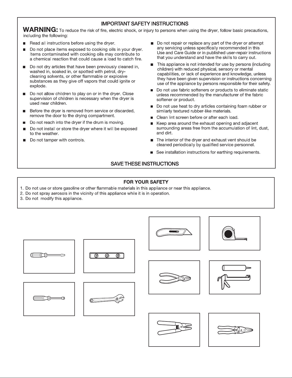
Tools and Parts:
Gather required tools and parts before starting installation.
Flat-blade screwdriver
6,2 mm (1/4") nut driver
Level
Adjustable wrench that
opens to 25 mm (1") or a
hex-head socket
Utility knife
Pliers
Wire stripper
(direct wire installations)
Tape measure
Caulking gun and
compound (for installing
new exhaust vent)
Tin snips
(new vent installations)
3
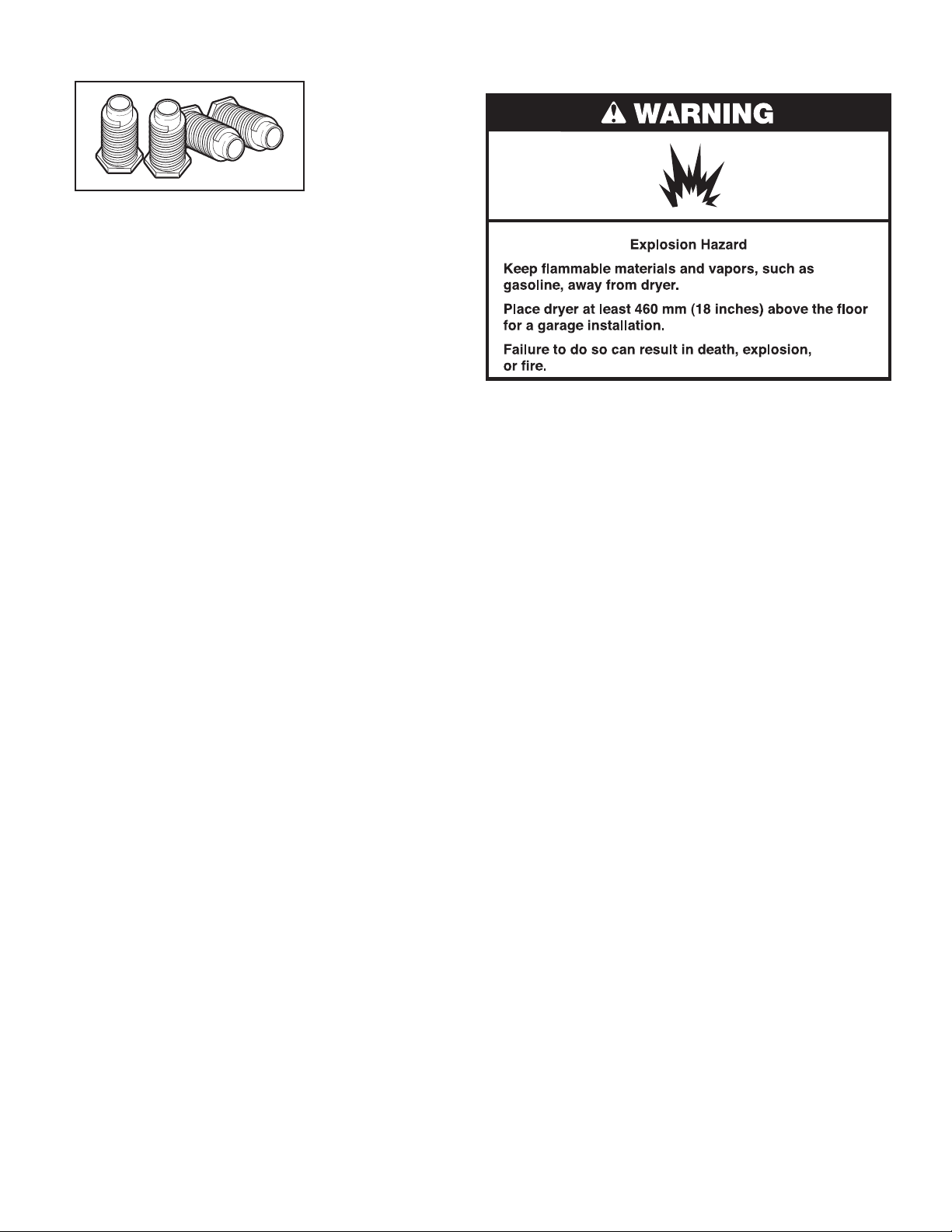
Parts supplied (all models):
Leveling legs (4)
Parts package is located in dryer drum. Check that all parts
are included.
Parts needed: (not supplied with dryer)
■ Electric Cord and Plug
■ Vent clamps
■ Vent elbows and ductwork
If using a power supply cord:
Use a UL listed power supply cord kit marked for use with dryers.
The kit should contain:
■ A UL listed 30-amp power supply cord, rated 240 volt
minimum. The cord should be type SRD or SRDT and be at
least 4 ft (1.22 m) long. The wires that connect to the dryer
must end in ring terminals or spade terminals with upturned
ends.
■ A UL listed strain relief.
Additional parts may be required, depending on your installation.
Check local codes. Check existing electrical supply and venting.
Read “Electrical Requirements” and “Venting Requirements”
before purchasing parts.
LOCATION REQUIREMENTS
Select proper location for your dryer to improve performance
and minimize noise. Check code requirements. Some codes limit,
or do not permit, installation of the dryer in garages, closets,
mobile homes, or sleeping quarters. Contact your local building
inspector.
You will need:
■ A location that allows for proper exhaust installation. The
dryer must be exhausted to the outdoors. See “Venting
Requirements.”
■ A oor that will support the dryer and a total weight (dryer
and load) of 90,7 kg (200 lbs). The combined weight of a
companion appliance should also be considered.
■ A level oor with maximum slope of 25 mm (1") under entire
dryer. If slope is greater than 25 mm (1"), install Extended
Dryer Feet Kit. Clothes may not tumble properly and models
with automatic sensor cycles may not operate correctly if
dryer is not level.
■ It is important to make sure the room has an adequate air
supply for drying operation. The operation of this appliance
may affect the operation of other appliances which take their
air supply for safe combustion from the same room.
■ Adequate ventilation must be provided to avoid a backow
of gases into the room from appliances burning other
fuels, including open res. If in doubt consult the appliance
manufacturers.
IMPORTANT: The dryer must not be installed or stored in an
area where it will be exposed to water and/or weather. Do not
operate your dryer at temperatures below 7°C (45°F). At lower
temperatures, the dryer might not shut off at the end of an
automatic cycle. Drying times can be extended.
Proper installation is your responsibility.
4
Installation clearances:
279 mm
For each arrangement, consider allowing more space for ease of
installation and servicing; spacing for companion appliances and
clearances for walls, doors, and oor moldings. Space must be
large enough to allow door to fully open. Add spacing on all sides
of dryer to reduce noise transfer. If a closet door or louvered door
is installed, top and bottom air openings in door are required.
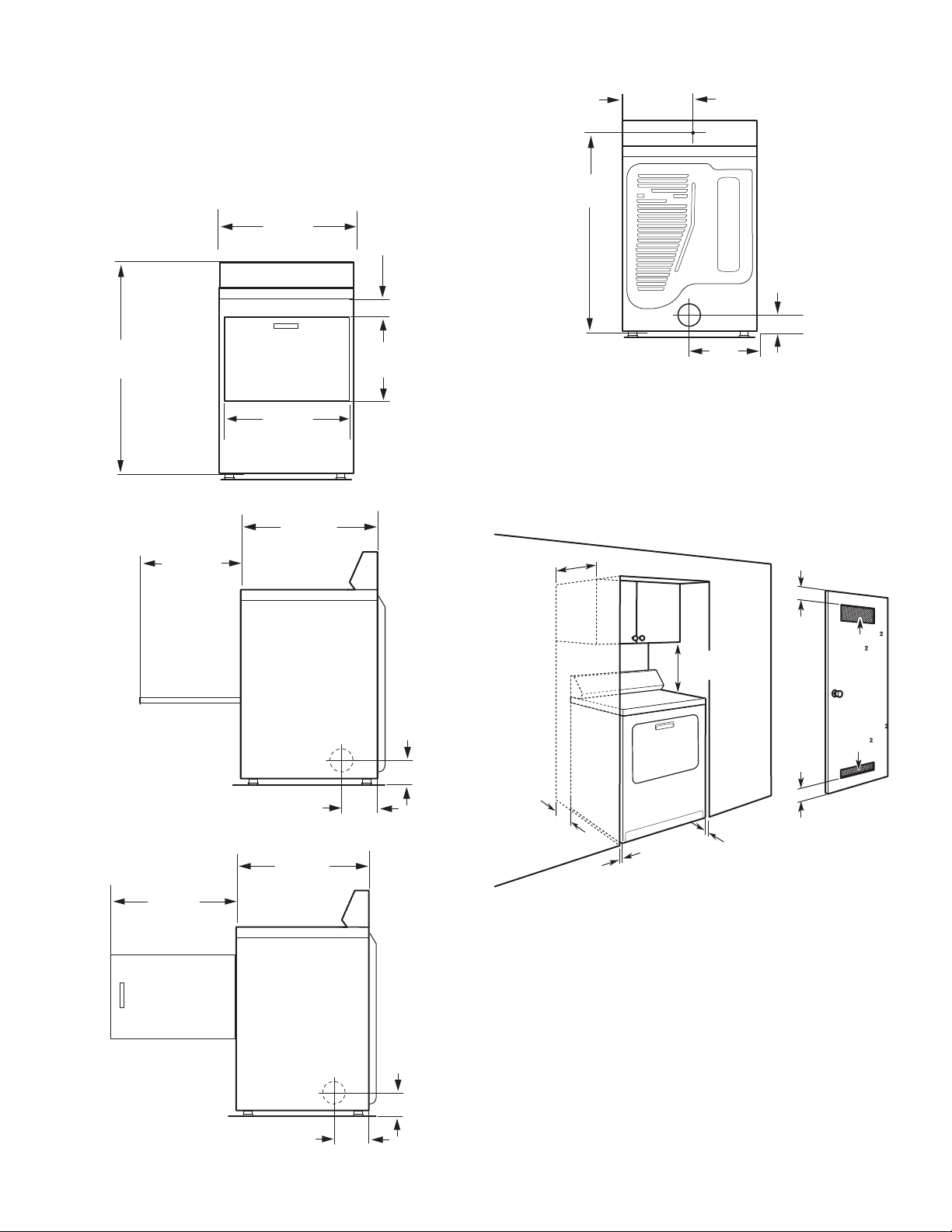
Dryer Dimensions
Front View:
686 mm
(27")
98 mm
7
.5
(3
/8
")
Back View:
972 mm
1
.5
")
(38
/
4
(11")
100 mm
(4")
1095 mm
1
.5
")
(43
/8
Side View:
356 mm
(14")
Side View of Side Swing Door:
578 mm
3
(22
.5
")
/4
578 mm
3
.5
(22
/4
743 mm
(29
260 mm
1
(10
.5
/4
743 mm
(29
.5 ")
260 mm
1
(10
.5
/4
")
1
1
.5
")
/4
")
489 mm
1
.5
(19
/8
")
359 mm
1
.5
(14
/8
")
Recessed Area and Closet Installation
This dryer may be installed in a recessed area or closet. If
a closet door or louvered door is installed, the minimum
unobstructed air openings in the top and bottom of the door are
required. For recessed area and closet installations, minimum
clearances can be found on the serial tag on the dryer.
")
/4
356 mm
(14") max.
76 mm
(3")
310 mm
(48" )
155 mm
(24" )
108 mm
1
(4
.5
")
/4
108 mm
1
(4
.5
")
/4
457 mm
(18")
76 mm
(3")
102 mm
(4")
25 mm
(1")
■ Dimensions shown are minimum spacings required. Consider
25 mm
(1")
allowing more space for ease of installation, servicing, and
compliance with local codes and ordinances.
■ Additional spacing for companion appliances and clearances
for walls, doors, and oor moldings should also be
considered. Add spacing of 25 mm (1") on all sides of dryer
to reduce noise transfer.
■ This dryer must not be installed behind a lockable door,
a sliding door or a door with a hinge on the opposite side
to that of the dryer.
■ The dryer must be exhausted outdoors.
■ No other fuel-burning appliance may be installed in the same
closet as the dryer.
5
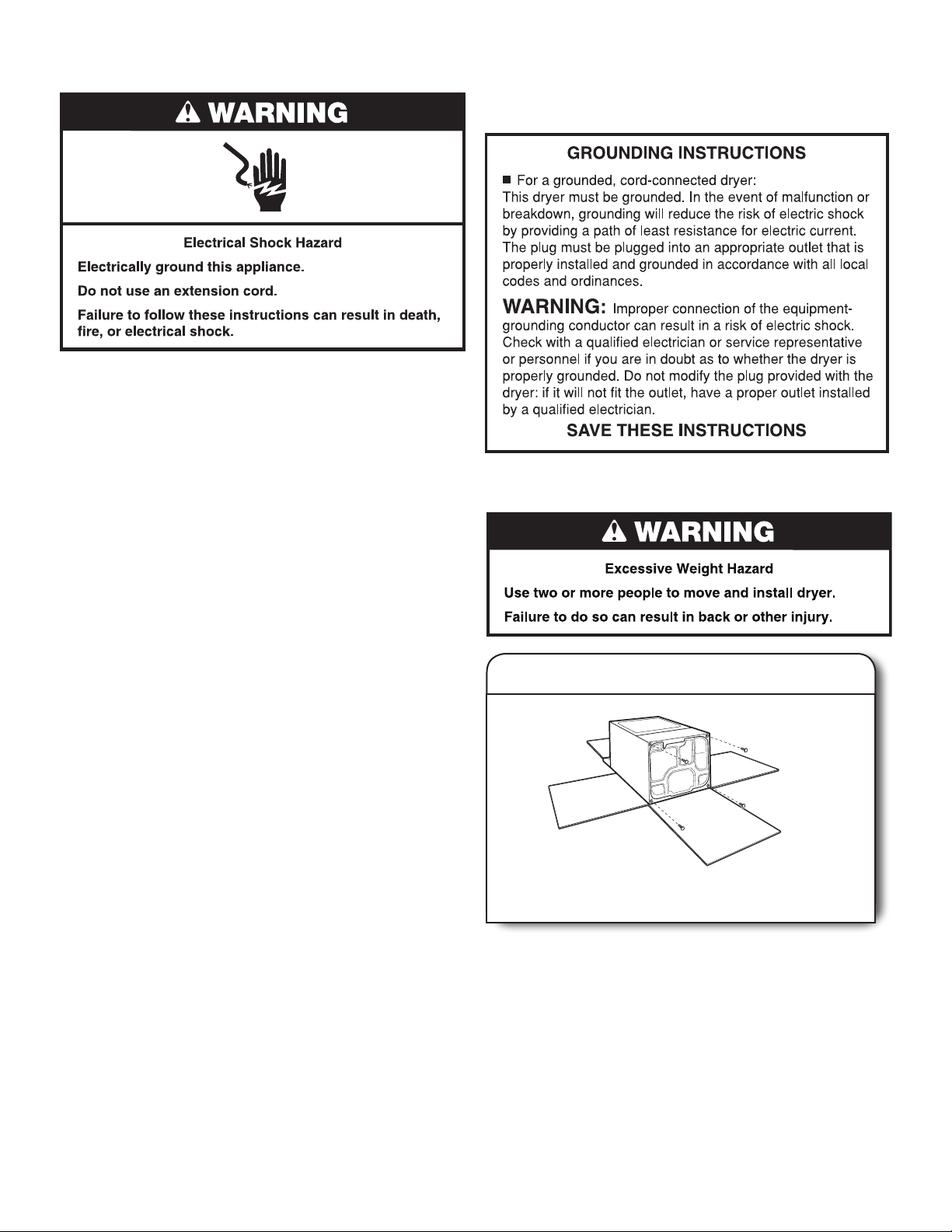
ELECTRICAL REQUIREMENTS
This dryer is supplied without an electric cord and plug.
It is your responsibility:
■ To contact a qualied electrical installer.
■ To be sure that the electrical connection is adequate and in
conformance with all local codes and ordinances.
■ To supply the required single phase, 240 volt, 60 Hz, AC
only electrical supply on a separate 30-amp circuit fused on
both sides of the line. A time-delay fuse or circuit breaker is
recommended. Connect to an individual branch circuit. Do
not have a fuse in the neutral or grounding circuit.
■ Do not use an extension cord.
■ If codes permit and a separate ground wire is used, it is
recommended that a qualied electrician determine that the
ground path is adequate.
Electrical Connection
To properly install your dryer, you must determine the type of
electrical connection you will be using and follow the instructions
provided for it here.
If using a power supply cord:
Use a UL listed power supply cord kit marked for use with
clothes dryers. The kit should contain:
■ A UL listed 30-amp power supply cord, rated 240 volt
minimum. The cord should be type SRD or SRDT and be at
least 4 ft (1.22 m) long. The wires that connect to the dryer
must end in ring terminals or spade terminals with upturned
ends.
■ A UL listed strain relief.
Connecting by direct wire:
Power supply cable must match power supply and be:
■ Flexible armored cable or nonmetallic sheathed copper cable
(with ground wire), covered with exible metallic conduit. All
current-carrying wires must be insulated.
■ 10-gauge solid copper wire (do not use aluminum).
■ At least 5 ft (1.52 m) long.
Recommended Grounding Method
■ It is your responsibility to contact a qualied electrical installer
to ensure that the electrical installation is adequate and in
conformance with all local codes and ordinances.
INSTALL LEVELING LEGS
1.
Prepare dryer for leveling legs
To avoid damaging oor, use a large at piece of cardboard
from dryer carton; place under entire back edge of dryer.
Firmly grasp dryer body (not console panel) and gently lay
dryer down on cardboard.
6
2.
Screw in leveling legs
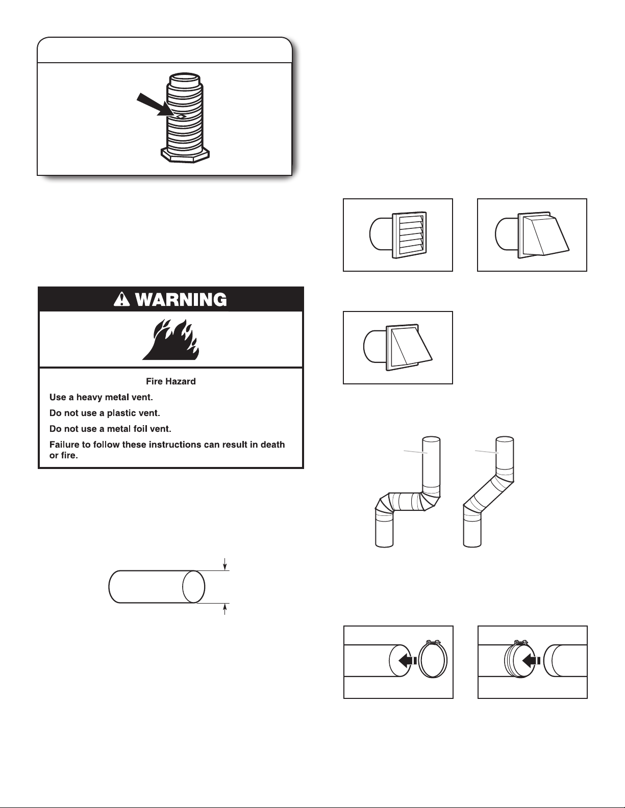
diamond
marking
■ Do not install in enclosed walls, ceilings, or oors.
■ The total length should not exceed 2.4 m (7¾ ft.).
NOTE: If using an existing vent system, clean lint from entire
length of the system and make sure exhaust hood is not
plugged with lint. Replace plastic or metal foil vents with rigid
metal or exible metal vents. Review “Vent System Chart” and
if necessary, modify existing vent system to achieve best drying
performance.
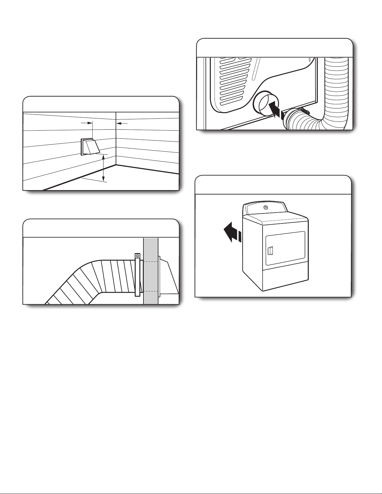
Exhaust hoods:
■ Must be at least 305 mm (12") from ground or any object that
may obstruct exhaust (such as owers, rocks, bushes, or
snow).
Examine leveling legs, nd diamond marking. Screw legs into
leg holes by hand, use a wrench to nish turning legs until
diamond marking is no longer visible.
Now stand the dryer on its feet. Slide the dryer until it is
close to its nal location. Leave enough room for electrical
connection and to connect the exhaust vent.
VENTING REQUIREMENTS
Recommended Styles:
Louvered Hood
Box Hood
Acceptable Style:
Angled Hood
Elbows:
■ 45° elbows provide better airow than 90° elbows.
Good Better
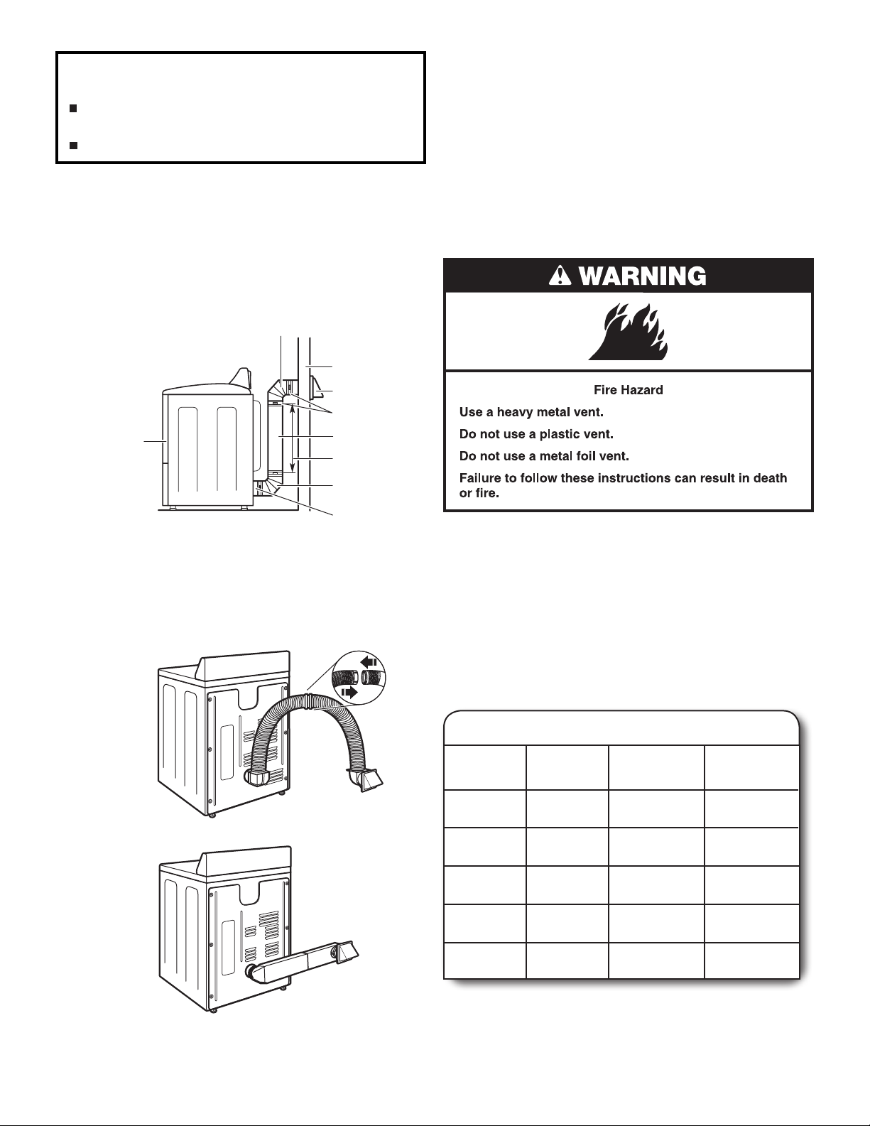
WARNING: To reduce the risk of re, this dryer MUST BE
EXHAUSTED OUTDOORS.
IMPORTANT: Observe all governing codes and ordinances.
Dryer exhaust must not be connected into any gas vent,
chimney, wall, ceiling, attic, crawlspace, or a concealed space
of a building. Only rigid or exible metal vent shall be used for
exhausting.
102 mm
(
4"
)
■ Only a 102 mm (4") heavy metal exhaust vent and clamps
may be used. Do not install metal vent that is smaller than
102 mm (4") in diameter.
■ Do not use plastic, non-metal, or metal foil vent.
Rigid metal vent
■ Recommended for best drying performance and to avoid
crushing and kinking.
Flexible metal vent: (Acceptable only if accessible to clean)
■ Must be fully extended and supported in nal dryer location.
■ Remove excess exible metal vent to avoid sagging
and kinking that may result in reduced airow and poor
performance.
Clamps:
■ Use clamps to seal all joints.
■ Exhaust vent must not be connected or secured with screws
or other fastening devices that extend into interior of duct
and catch lint. Do not use duct tape.
Vent products can be purchased from your dealer. For more
information, see “Assistance or Service” section in your “Use
and Care Guide.”
7
Improper venting can cause moisture and lint to collect
indoors, which may result in:
Moisture damage to woodwork, furniture, paint,
wallpaper, carpets, etc.
Housecleaning problems and health problems.
PLAN VENT SYSTEM
The design of the ue system should ensure that any condensate
formed when operating the appliance from cold, is either retained
and subsequently evaporated or discharged. Following these
installation instructions should adequately meet this requirement.
Recommended exhaust installations
Typical installations vent the dryer from the rear of the dryer.
Other installations are possible.
B
C
D
E
If you prefer, dryer may be converted to exhaust out right side,
left side, or through bottom. You must contact your local dealer
to have dryer converted.
Determine vent path:
■ Select route that will provide straightest and most direct
path outdoors.
■ Plan installation to use fewest number of elbows and turns.
■ When using elbows or making turns, allow as much room
as possible.
■ Bend vent gradually to avoid kinking.
■ Use as few 90° turns as possible.
F
G
B
H
A. Dryer
B. Elbow
C. Wall
D. Exhaust hood
A
E. Clamps
F. Rigid metal or exible metal vent
G. Vent length necessary to connect elbows
H. Exhaust outlet
Alternate installations for close clearances
Venting systems come in many varieties. Select the type best
for your installation. Two close-clearance installations are shown.
Refer to the manufacturer’s instructions.
Over-The-Top installation (also available with one offset elbow)
Determine vent length and elbows needed for best
drying performance:
■ Use following Vent System Chart to determine type of vent
material and hood combinations acceptable to use.
NOTE: Do not use vent runs longer than those specied
in Vent System Chart. Exhaust systems longer than those
specied will:
■ Shorten life of dryer.
■ Reduce performance, resulting in longer drying times
and increased energy usage.
Vent System Chart
Number of
90° turns
or elbows
0
1
Type
of vent
Rigid metal
Rigid metal
Box/louvered
hoods
15,8 m (52 ft.)
13,4 m (44 ft.)
Angled
hoods
13,4 m (44 ft.)
11,0 m (36 ft.)
2
3
4
Rigid metal
Rigid metal
Rigid metal
11,0 m (36 ft.)
8,2 m (27 ft.)
6,1 m (20 ft.)
18,5 m (28 ft.)
6,4 m (21 ft.)
4,3 m (14 ft.
The Vent System Chart provides venting requirements that
will help achieve best drying performance.
Periscope installation
NOTE: Side and bottom exhaust installations have a 90° turn
inside the dryer. To determine maximum exhaust length, add
one 90° turn to the chart.
8
305 mm
(
12" mín.
)
305 mm
(
12" mín.
)
The maximum length using a 51 mm x 152 mm (2"x 6")
rectangular vent with 2 elbows and a 64 mm (2-1/2") exhaust
hood is 2,4 m (8 ft).
For exhaust systems not covered by the Vent System Chart (such
as multiple unit hookups, plenums, and power-assist fans), see
Service Manual. (To purchase the Service Manual, contact your
local authorized service dealer.)
INSTALL VENT SYSTEM
1.
Install exhaust hood
Install exhaust hood and use caulking compound to seal
exterior wall opening around exhaust hood.
CONNECT VENT
1.
Connect vent to exhaust outlet
Using a 102 mm (4") clamp, connect vent to exhaust outlet
in dryer. If connecting to existing vent, make sure vent is
clean. Dryer vent must t over dryer exhaust outlet and inside
exhaust hood. Check that vent is secured to exhaust hood
with a 102 mm (4") clamp.
2.
Move dryer to nal location
2.
Connect vent to exhaust hood
Vent must t over the exhaust hood. Secure vent to exhaust
hood with 102 mm (4") clamp. Run vent to dryer location
using straightest path possible. Avoid 90° turns. Use clamps
to seal all joints. Do not use duct tape, screws, or other
fastening devices that extend into interior of vent to secure
vent, because they can catch lint.
Move dryer to nal location. Avoid crushing or kinking vent.
After dryer is in place, remove corner posts and cardboard
from under the dryer.
9
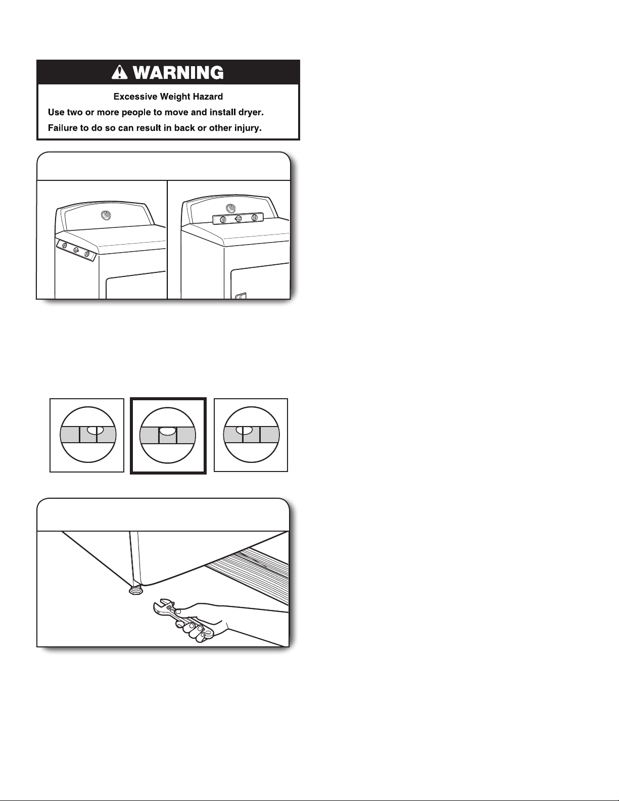
LEVEL DRYER
1.
Level Dryer
Check levelness of dryer from side to side. Repeat from
front to back.
NOTE: The dryer must be level to reduce noise and assure
proper performance.
If legs are not long enough to level dryer, order Extended Dryer
Feet kit (sold two legs per kit), from your dealer.
Not Level LEVEL Not Level
Tighten and adjust leveling legs
2.
COMPLETE INSTALLATION
CHECKLIST
Check that all parts are now installed. If there is an extra
q
part, go back through steps to see what was skipped.
Check that you have all of your tools.
q
Dispose of/recycle all packaging materials.
q
Check dryer’s nal location. Be sure vent is not crushed
q
or kinked.
For power supply cord installation, plug into an outlet.
q
For direct wire installation, turn on power.
Check that dryer is level. See “Level Dryer”.
q
Remove lm on console and any tape remaining on dryer.
q
Wipe dryer drum interior thoroughly with a damp cloth
q
to remove any dust.
Read “Dryer Use” in your Use and Care Guide.
q
Set the dryer on a full heat cycle (not an air cycle) for
q
20 minutes and start the dryer.
If the dryer will not start, check the following:
■ Controls are set in a running or “On” position.
■ Start button has been pushed rmly.
■ Dryer is plugged into an outlet and/or electrical supply
is on.
■ Household fuse is intact and tight, or circuit breaker has
not tripped.
■ Dryer door is closed.
When the dryer has been running for 5 minutes, open the
q
dryer door and feel for heat. If you feel heat, cancel cycle and
close the door.
If you do not feel heat, turn off dryer, and check the
following:
■ There may be 2 household fuses or circuit breakers for
the dryer. Check that both fuses are intact and tight,
or that both circuit breakers have not tripped. If there
is still no heat, contact a qualied technician.
NOTE: You may notice an odor when the dryer is rst heated.
This odor is common when the heating element is rst used.
The odor will go away.
If dryer is not level, prop up using a wood block, use wrench
to adjust legs up or down, and check again for levelness.
Once legs are level, make sure all four legs are snug against
the ground.
10

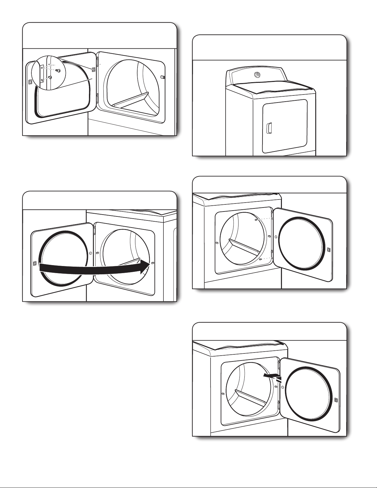
REVERSE DOOR SWING (OPTIONAL)
(MODELS WITH SIDE SWINGS DOORS ONLY)
If your door is the 29" Large Side-Swing Door,
follow steps 1-6.
If your door is the 29" Super Wide Side-Swing Door,
follow steps 1-13.
NOTE: Magnetized screw driver is helpful.
Remove bottom screws
2.
Open dryer door. Remove bottom screws from dryer cabinet
side of hinges. Loosen (do not remove) top screws from dryer
cabinet side of hinges.
3.
Lift door off top screws
Large Side-Swing Door
1.
Place towel on dryer
Place towel on top of dryer to avoid damaging the surface.
Lift door until top screws in cabinet are in large part of hinge
slot. Pull door forward off screws. Set door on top of dryer.
Remove top screws from dryer cabinet.
4.
Remove and transfer hinge
hole plugs
Use a small, at-blade screwdriver to gently remove 4 hinge
hole plugs on left side of dryer cabinet. Insert plugs into hinge
holes on opposite side of dryer cabinet.
11
Insert screws in hinge holes on
5.
dryer cabinet
NOTE: Two people maybe needed to reinstall door.
Insert screws into bottom holes on left side of dryer cabinet.
Tighten screws halfway. Position door so large end of door
hinge slot is over screws. Slide door up so screws are in
bottom of slots. Tighten screws. Insert and tighten top
screws in hinges.
6.
Check door strike alignment
Super Wide Side-Swing Door
1.
Place towel on dryer
Place towel on top of dryer to avoid damaging the surface.
2.
Remove bottom screws
Close door and check that door strike aligns with door
catch. If needed, slide door catch left or right within slot
to adjust alignment.
12
Open dryer door. Remove bottom screws from dryer cabinet
side of hinges. Loosen (do not remove) top screws from
dryer cabinet side of hinges.
3.
Lift door off top screws
Lift door until top screws in dryer cabinet are in large part of
hinge slot. Pull door forward off screws. Set door (handle side
up) on top of dryer. Remove top screws from dryer cabinet.
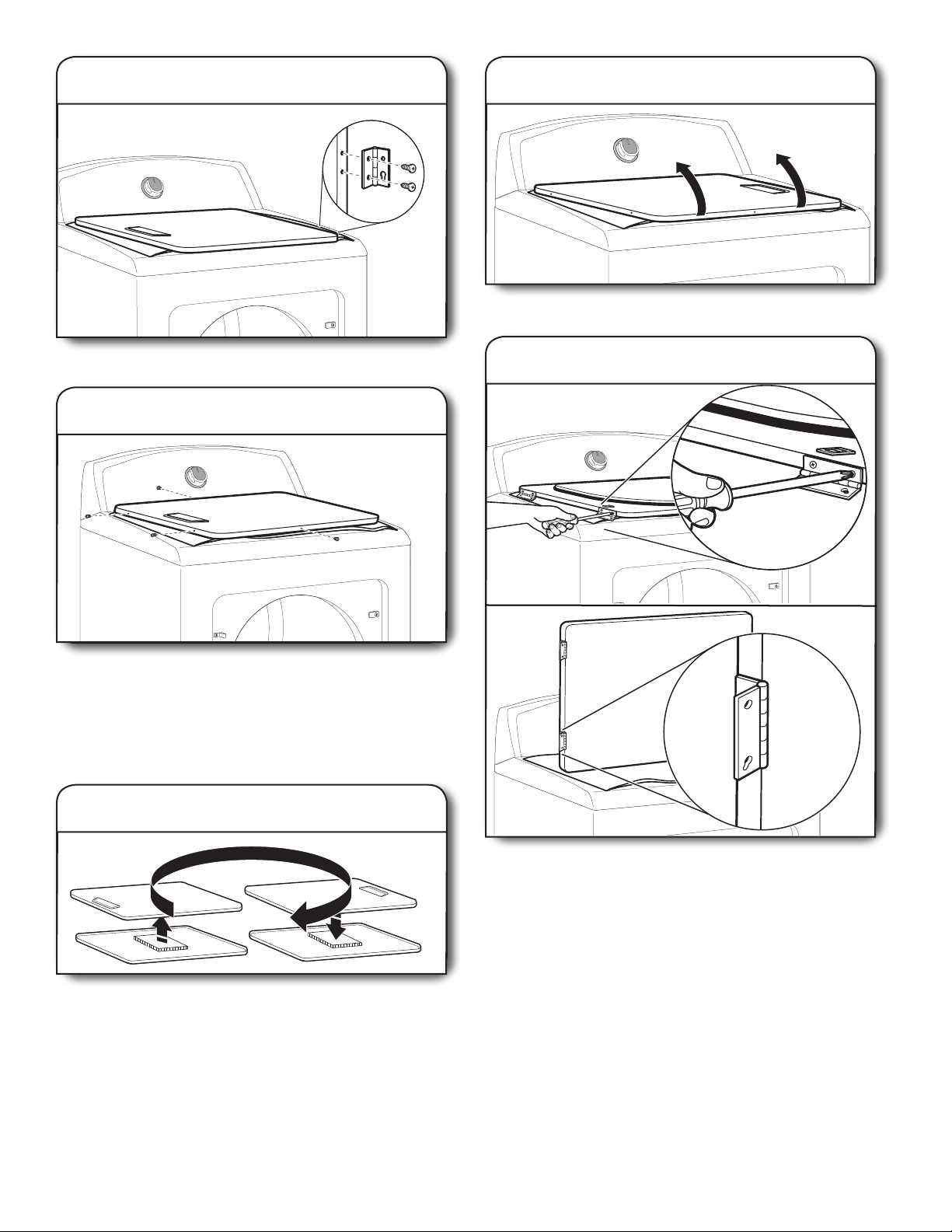
Remove screws from hinges
4.
7.
Flip door over
Flip door over so handle side is down.
Remove screws attaching hinges to door.
Remove screws from door
5.
Remove screws at top, bottom, and side of door
(4 screws). Keep door screws separate from hinge screws
as they are different sizes. Holding door over towel on dryer,
grasp sides of outer door and lift to separate it from inner
door.
NOTE: Do not pry apart with putty knife or screwdriver.
Do not pull on door seal or plastic door catches.
Rotate outer door
6.
8.
Attach door hinges
Take outer door and rotate in 180º and set it back down on
inner door. Be certain to keep cardboard spacer centered
between doors. Reattach outer door panel to inner door
panel so handle is on the side where hinges were just
removed. Insert 4 door screws.
Reattach door hinges to dryer door so that the larger hole is
at the bottom of the hinge.
13
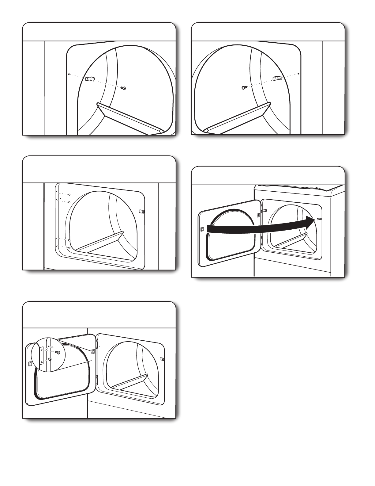
9.
Remove door strike
12.
Remove door strike plug
Remove door strike from dryer cabinet and set aside.
10.
Remove and transfer
hinge hole plugs
Use a small, at-blade screwdriver to gently remove 4 hinge
hole plugs on left side of dryer cabinet. Transfer plugs into
hinge holes on opposite side of dryer cabinet.
11.
Insert screws in hinge holes on
dryer cabinet
Remove door strike plug. Insert the door strike removed in
Step 9 into hole and secure with screw. Insert door strike
plug into original door strike hole and secure with screw.
13.
Close door and check that door strike aligns with door
catch. If it is needed, slide door catch left or right within slot
to adjust alignment.
Check door strike alignment
TROUBLESHOOTING
See the “Use and Care Guide” to possibly avoid the cost of a
service call.
NOTE: Two people maybe needed to reinstall door.
Insert screws into the bottom holes on left side of dryer
cabinet. Tighten screws halfway. Position door so large end
of door hinge slot is over screws. Slide door up so screws
are in bottom of slots. Tighten screws. Insert and tighten top
screws in hinges.
14
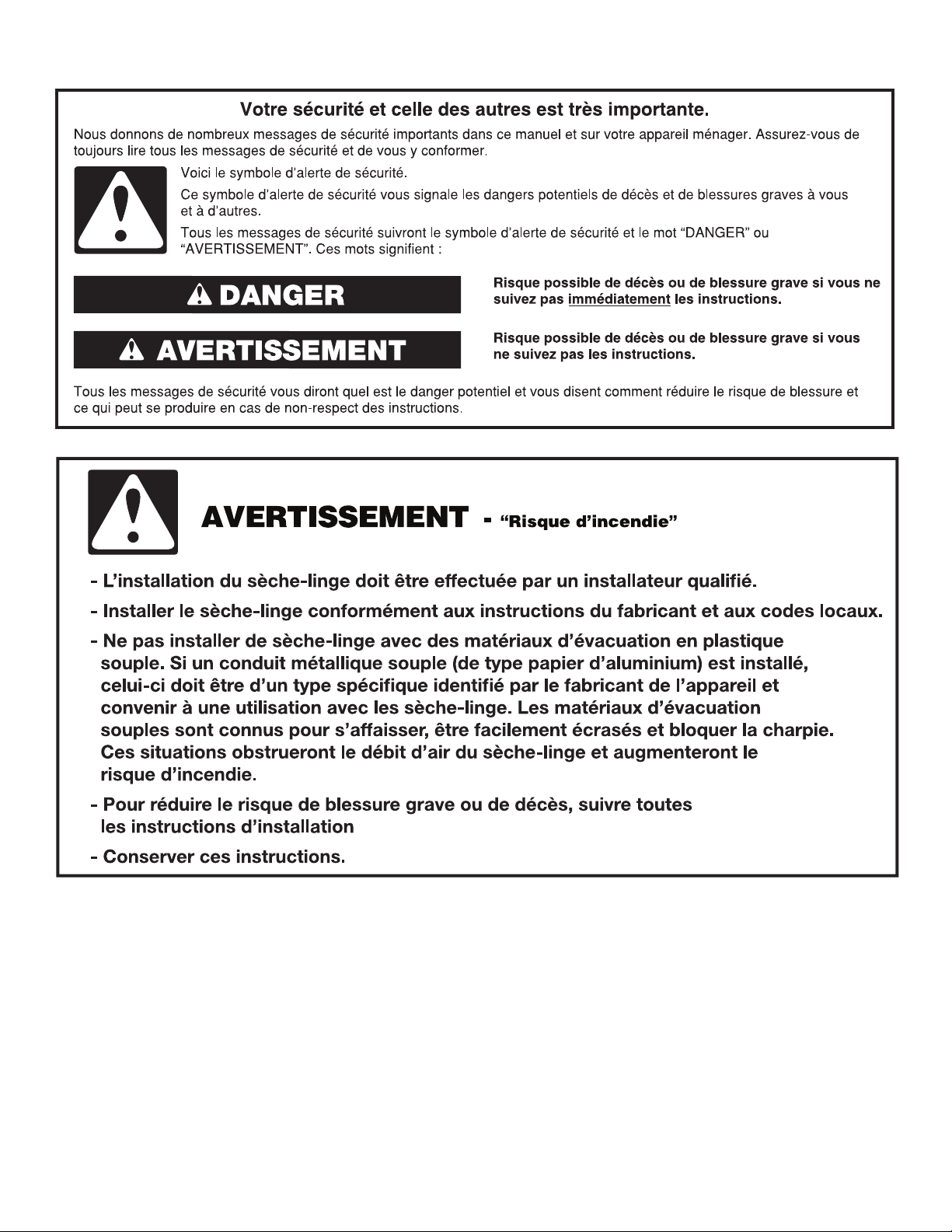
SECURITE DU SECHE-LINGE
15
16
EXIGENCES D’INSTALLATION
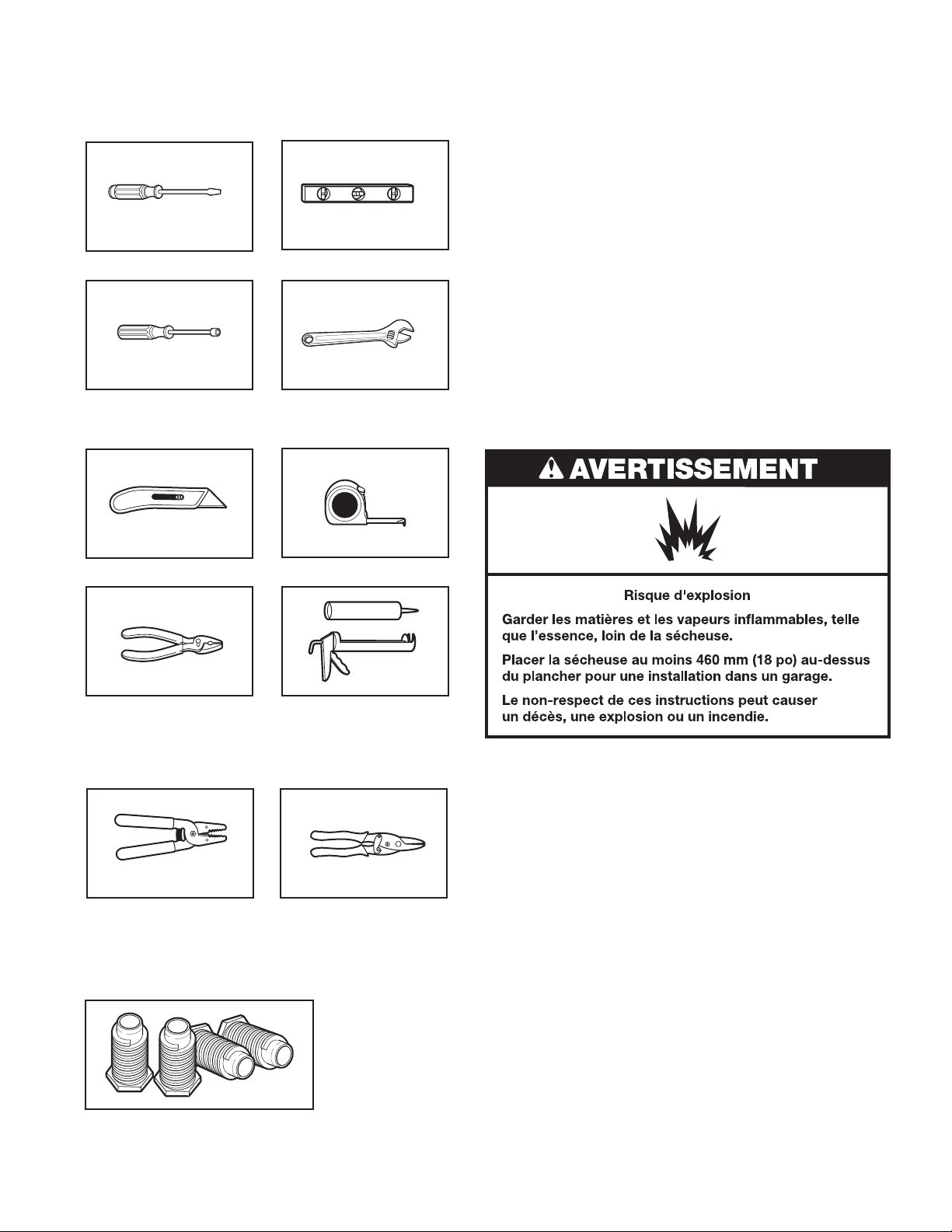
Outillage et Pièces
Rassembler les outils et piéces nécessaires avant de commencer
l’installation.
Tournevis à lame plate
Clé à douille ou tourneécrou de 6,2 mm (1/4")
Niveau
Clé à molette avec ouverture
jusqu’à 25 mm (1") ou clé à
douille hexagonale
Pièces nécessaires : (non fournies avec le sèche-linge)
■ Cordon d’alimentation
■ Clapets d’évacuation
■ Coudes et les conduits de ventilation
En cas d’utilisation d’un câble d’alimentation
électrique :
Utiliser un ensemble de câble d’alimentation électrique
homologué UL marqué pour utilisation avec les sèche-linge.
L’ensemble doit contenir :
■ Un câble d’alimentation électrique homologué UL de
30 ampères, 240 volts minimum. Le câble doit être de type
SRD ou SRDT et mesurer au moins 4 pi (1,22 m) de long.
Les ls raccordés au sèche-linge doivent se terminer par des
cosses rondes ou à fourche à pointes relevées.
■ Un serre-câble (homologation UL).
Des pièces supplémentaires seront peut-être nécessaires,
selon l’installation. Consulter les codes locaux. Vérier
l’alimentation électrique et le circuit d’évacuation existants.
Consulter “Spécications électriques” et “Exigences concernant
l’évacuation” avant d’acheter les pièces.
EXIGENCES D’EMPLACEMENT
Couteau universel
Pince
Pince à dénuder
(installations avec
raccordement par
câblage direct)
Mètre à ruban
Pistolet à calfeutrage et
composé de calfeutrage
(pour l’installation
d’un nouveau conduit
d’évacuation)
Cisaille de ferblantier
(pour l’installation
d’un nouveau conduit
d’évacuation)
Pièces fournies (pour tous les modèles) :
Pieds de nivellement (4)
Retirer le sac de pièces du tambour du sèche-linge. Vérier
la présence de toutes les pièces.
Choisir un emplacement approprié pour le sèche-linge an
d’en améliorer la performance et de réduire au maximum le
bruit qu’il produit. Vérier les spécications des codes. Certains
codes limitent ou interdisent l’installation des sèche-linge dans
un garage, un placard, une maison mobile ou une chambre à
coucher. Contacter l’inspecteur en bâtiments local.
Il vous faudra :
■ Un emplacement permettant une évacuation appropriée.
L’évacuation du sèche-linge doit se faire à l’extérieur. Voir
“Exigences concernant l’évacuation”.
■ Le plancher doit pouvoir soutenir le poids du sèche-linge
de 90,7 kg (200 lb). Tenir également compte du poids des
appareils voisins.
■ Un plancher de niveau avec une pente maximale de
1" (25 mm) sous l’ensemble du sèche-linge. Si l’inclinaison
est supérieure à 25 mm (1"), installer l’ensemble de pieds
d’extension. Si le sèche-linge n’est pas d’aplomb, il est
possible que le linge ne culbute pas convenablement et que
les programmes commandés par détecteurs automatiques ne
fonctionnent pas correctement.
■ Il est important de s’assurer que la pièce dans laquelle se
trouve l’appareil possède un approvisionnement d’air sufsant
pour permettre son bon fonctionnement. L’utilisation de cet
appareil peut affecter celle d’autres appareils dont la source
d’approvisionnement en air se fait dans la même pièce pour
une combustion sans danger.
17
 Loading...