

Whirlpool 3LWED5500YW, 3LWGD4800YQ Installation Instructions
ELECTRIC OR GAS DRYER
INSTALLATION INSTRUCTIONS
INSTRUCTIONS D’INSTALLATION DU SECHE-LINGE
ELECTRIQUE OU A GAZ
SECADORA A GAS O ELÉCTRICA
INSTRUCCIONES DE INSTALACIÓN
Table of Contents
DRYER SAFETY .........................................................................2
DRYER DISPOSAL ..................................................................... 5
INSTALLATION REQUIREMENTS .............................................5
Tools and Parts ......................................................................5
LOCATION REQUIREMENTS .................................................... 6
ELECTRICAL REQUIREMENTS ................................................ 7
GAS REQUIREMENTS ............................................................... 8
INSTALL LEVELING LEGS ......................................................... 9
VENTING REQUIREMENTS ...................................................... 9
This is the original language (English)
Table des matiéres
SECURITE DU SECHE-LINGE ................................................ 19
ELIMINATION DU SECHE-LINGE ........................................... 22
EXIGENCES D’INSTALLATION ...............................................22
Outillage et Pièces ............................................................... 22
EXIGENCES D’EMPLACEMENT ............................................. 23
SPECIFICATIONS ELECTRIQUES .......................................... 24
EXIGENCES CONCERNANT L’ALIMENTATION EN GAZ ...... 25
INSTALLATION DES PIEDS DE NIVELLEMENT .................... 26
EXIGENCES CONCERNANT L’EVACUATION ........................ 27
PLANIFICATION DU SYSTEME D’EVACUATION ................... 28
PLAN VENT SYSTEM ............................................................... 10
INSTALL VENT SYSTEM ......................................................... 12
CONNECT VENT ...................................................................... 12
LEVEL DRYER .......................................................................... 13
COMPLETE INSTALLATION CHECKLIST ..............................13
REVERSE DOOR SWING (OPTIONAL) ................................... 14
NON-USE, STORAGE, AND MOVING CARE.......................... 17
TECHNICAL SPECIFICATIONS ............................................... 18
TROUBLESHOOTING .............................................................. 18
INSTALLATION DU CONDUIT D’EVACUATION ..................... 30
RACCORDEMENT DU CONDUIT D’EVACUATION ...............30
REGLAGE DE L’APLOMB DU SECHE-LINGE ........................ 31
ACHEVER L’INSTALLATION LISTE DE VERIFICATION .........31
INVERSION DU SENS DE L’OUVERTURE DE LA PORTE
(FACULTATIF) ........................................................................... 32
PRÉCAUTIONS À PRENDRE EN CAS DE NON-UTILISATION,
D’ENTREPOSAGE OU DE DÉMÉNAGEMENT
CARACTERISTIQUES TECHNIQUES ..................................... 36
DEPANNAGE ............................................................................36
......................... 35
Ceci est une traduction de l’anglais.
Índice
SEGURIDAD DE LA SECADORA ............................................ 37
ELIMINACIÓN DE LA SECADORA ......................................... 40
REQUISITOS DE INSTALACIÓN ............................................. 40
Piezas y herramientas: ........................................................ 40
REQUISITOS DE UBICACIÓN ................................................. 41
REQUISITOS ELÉCTRICOS .................................................... 42
REQUISITOS DEL SUMINISTRO DE GAS .............................. 43
INSTALACIÓN DE LAS PATAS NIVELADORAS...................... 44
REQUISITOS DE VENTILACIÓN ............................................. 44
PLANIFICACIÓN DEL SISTEMA DE VENTILACIÓN .............. 46
Traducido del inglés.
W10592557B - EN/FR/SP/AR
W10592558B - PT/GR/IT/DE
INSTALACIÓN DEL SISTEMA DE VENTILACIÓN .................. 47
CONEXIÓN DEL DUCTO DE ESCAPE....................................48
NIVELACIÓN DE LA SECADORA............................................48
LISTA DE CONTROL DE LA INSTALACIÓN TERMINADA .... 49
CAMBIO DEL SENTIDO DE ABERTURA DE LA PUERTA
(OPCIONAL) ............................................................................. 49
CUIDADO DURANTE LA FALTA DE USO,
EL ALMACENAMIENTO Y LAS MUDANZAS ......................... 53
ESPECIFICACIONES TÉCNICAS ............................................ 54
SOLUCIÓN DE PROBLEMAS .................................................. 54
3LWED5500 3LWGD4800
3LWED4800 3LWED4900
3LMEDC100 3LMEDC300
DRYER SAFETY
2

3
Please contact the machine's owner for proper service and repairs
4
if the product appears damaged or defective.

DRYER DISPOSAL
INSTALLATION REQUIREMENTS
Tools and Parts:
Gather required tools and parts before starting installation.
Flat-blade screwdriver Wire stripper
6,2 mm (1/4") nut driver
Utility knife
#2 Phillips screwdriver
Adjustable wrench that opens
to 25mm (1") or hex-head
socket wrench (for adjusting
dryer feet)
Tape measure
(direct wire installations)
Putty knife
Caulking gun and
compound (for installing
new exhaust vent)
Tools needed for Gas installations:
Tin snips
(new vent installations)
Level
Pliers Vent clamps
204 mm (8") or 254 mm (10")
pipe wrench
Pipe joint compound
resistant to LP gas
5

Parts supplied (all models):
Leveling legs (4)
Parts package is located in dryer drum. Check that all parts
are included.
Parts needed: (not supplied with dryer)
■ Electric cord and plug*
■ Vent clamps
■ Vent elbows and ductwork
* For Electric Dryer only. Gas Dryers come with electric cord and
plug already installed.
For gas installation:
Check local codes and gas supplier, and read electrical, gas, and
venting requirements before purchasing parts.
Gas supply line must have:
■ Shutoff valve
Rigid gas supply line must be:
■ Minimum 12.5 mm (1/2") ID pipe
Flexible gas supply line must be:
■ Minimum 10 mm (3/8") ID approved exible hose
LOCATION REQUIREMENTS
Select proper location for your dryer to improve performance
and minimize noise. Check code requirements. Some codes limit,
or do not permit, installation of the dryer in garages, closets,
mobile homes, or sleeping quarters. Contact your local building
inspector.
You will need:
■ A location that allows for proper exhaust installation. The
dryer must be exhausted to the outdoors. See “Venting
Requirements.”
■ An earthed electrical outlet located within 610 mm (2 ft) of
either side of the dryer. See “Electrical Requirements.”
■ A oor that will support the dryer and a total weight (dryer
and load) of 90,7 kg (200 lbs). The combined weight of a
companion appliance should also be considered.
■ A level oor with maximum slope of 25 mm (1") under entire
dryer. If slope is greater than 25 mm (1"), install Extended
Dryer Feet Kit, Part No. 279810. Clothes may not tumble
properly and models with automatic sensor cycles may not
operate correctly if dryer is not level.
■ It is important to make sure the room has an adequate air
supply for drying operation. The operation of this appliance
may affect the operation of other appliances which take their
air supply for safe combustion from the same room.
■ Adequate ventilation must be provided to avoid a backow
of gases into the room from appliances burning other
fuels, including open res. If in doubt consult the appliance
manufacturers.
IMPORTANT: The dryer must not be installed or stored in an
area where it will be exposed to water and/or weather. Do not
operate your dryer at temperatures below 7°C (45°F). At lower
temperatures, the dryer might not shut off at the end of an
automatic cycle. Drying times can be extended.
L.P. Gas Conversion:
Gas conversion kit is available for purchase from your dealer. Full
instructions are supplied with the kit. Conversion must be made
by a competent technician.
Additional parts may be required, depending on your installation.
Check local codes. Check existing venting and electrical and gas
supply. Read “Electrical Requirements,” "Gas Requirements,"
and “Venting Requirements” before purchasing parts.
Proper installation is your responsibility.
Installation clearances:
For each arrangement, consider allowing more space for ease of
installation and servicing; spacing for companion appliances and
clearances for walls, doors, and oor moldings. Space must be
large enough to allow door to fully open. Add spacing on all sides
of dryer to reduce noise transfer. If a closet door or louvered door
is installed, top and bottom air openings in door are required.
6
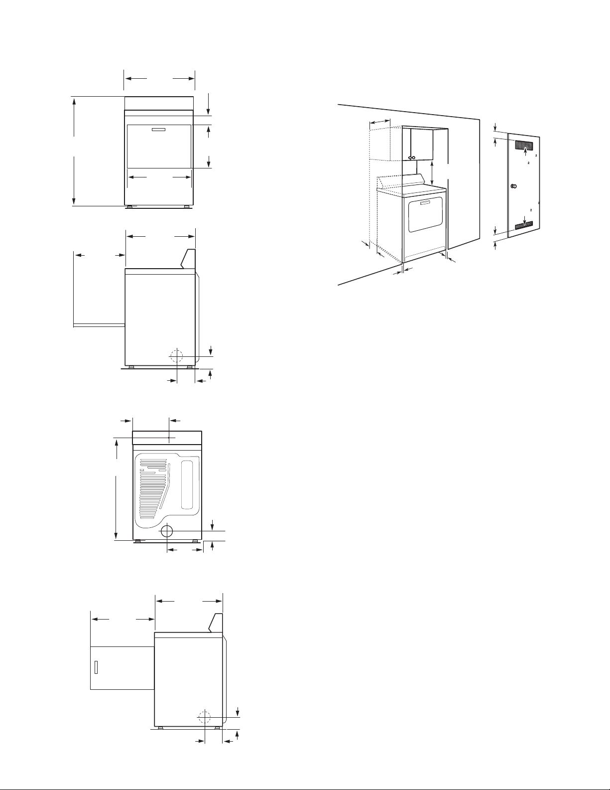
Dryer Dimensions
279 mm
.5
/
(1")
Front View:
1095 mm
1
.5
")
(43
/8
Side View:
356 mm
(14")
Back View:
686 mm
(27")
578 mm
.5
(22
743 mm
(29
.5
260 mm
1
(10
.5
/ 4
(11")
Recessed Area and Closet Installation
This dryer may be installed in a recessed area or closet.
If a closet door or louvered door is installed, the minimum
unobstructed air openings in the top and bottom of the door
98 mm
7
.5
")
(3
/8
489 mm
1
.5
")
(19
/8
3
")
/4
1
")
/4
108 mm
1
(4
.5
")
/ 4
")
are required. For recessed area and closet installations, minimum
clearances can be found on the serial tag on the dryer.
356 mm
(14") max.
76 mm
(3")
310 mm
(3")
(48" )
155 mm
(24" )
102 mm
(4")
25 mm
457 mm
(18")
25 mm
(1")
76 mm
■ Dimensions shown are minimum spacings required. Consider
allowing more space for ease of installation, servicing, and
compliance with local codes and ordinances.
■ Additional spacing for companion appliances and clearances
for walls, doors, and oor moldings should also be
considered. Add spacing of 25 mm (1") on all sides of dryer
to reduce noise transfer.
■ This dryer must not be installed behind a lockable door,
a sliding door or a door with a hinge on the opposite side
to that of the dryer.
■ The dryer must be exhausted outdoors.
■ No other fuel-burning appliance may be installed in the same
closet as the dryer.
972 mm
1
.5
")
(38
/
4
Side View of Side Swing Door:
578 mm
3
(22
.5
")
/4
359 mm
1
(14
743 mm
(29
.5
260 mm
1
(10
.5
/4
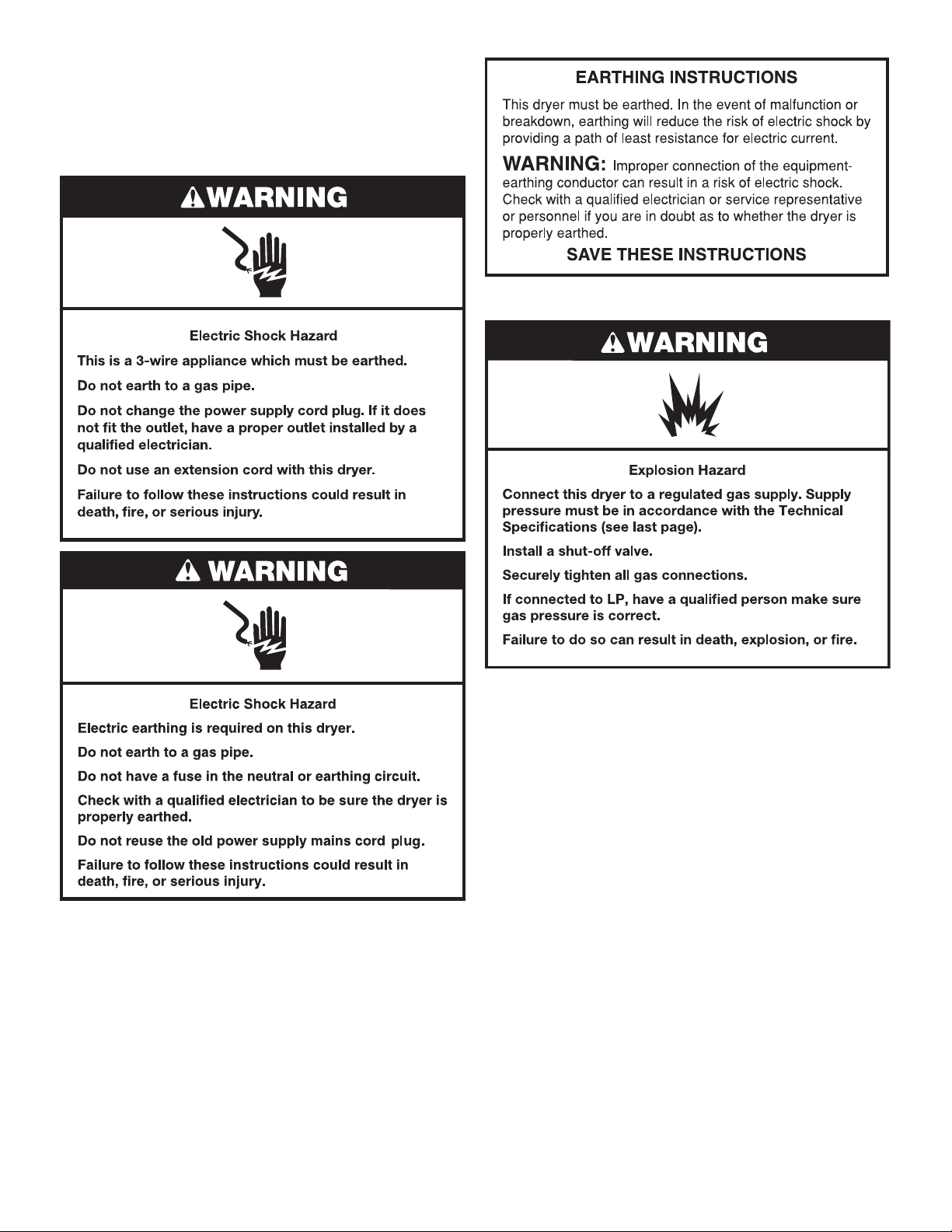
ELECTRICAL REQUIREMENTS
IMPORTANT: Observe all governing codes and ordinances.
For Electric Dryers Only:
100 mm
(4")
")
8
1
")
/4
108 mm
1
(4
.5
")
/4
")
This dryer is supplied without an electric cord and plug. It
must be connected by a qualied electrician to a single-phase
electricity supply at the voltage shown on the dataplate, using
a suitable xed wiring installation in accordance with local and
national wiring regulations.
■
A 3-wire circular cord of minimum conductor side of 4 mm2
cross-section area should be used.
■
A 30A supply fuse should be used, and a switch with a
minimum contact separation of 3 mm in both poles must be
incorporated into the xed wiring for dryer disconnection. The
dryer should be positioned so that the disconnection switch is
easily accessible to the user.
■
A cord clamp bushing is provided on the dryer, and should
be tightened on completion of wiring. The electrical mains
terminals are located behind the small rear access panel
(terminal block cover), and connections should be made in
accordance with the terminal markings. Remember to
replace the terminal access panel (terminal block cover).
7
For Both Gas and Electric Dryers:
NOTE: In accordance with the European EMC Directive
(89/336/EEC) the maximum electricity supply system impedance
to which the electric dryer should be connected is declared to be
0.29 Ohm + J0.18 Ohm.
This dryer has a Maximum power absorption/usage of 4700 watts.
GAS REQUIREMENTS
/
If code permits and an additional earth bond wire is used, it is
recommended that certied electrician determine that the earth
bond path is adequate.
Electrical Safety Standards: The manufacturer has chosen
compliance with IEC/EN.60335 standards as the most
appropriate for this product.
Do not use an adapter.
Recommended Earthing Method
■ It is your responsibility to contact a qualied electrical installer
to ensure that the electrical installation is adequate and in
conformance with all local codes and ordinances.
OBSERVE ALL GOVERNING CODES AND ORDINANCES.
Gas supply:
Check that dryer is equipped with the correct burner for the
particular type of gas supply. Burner information will be found
on the model/serial rating plate in the door well of the dryer. If
this information does not agree with the type of gas available,
see your dealer.
Natural Gas:
This dryer is factory adjusted for use with NATURAL GAS (G20),
and no further adjustment should be required at installation.
L.P. Gas:
This dryer is also certied for use with L.P. (propane or butane)
gases with appropriate conversion. No attempt shall be made to
convert the appliance from the gas specied on the model/serial
rating plate for use with a different gas without consulting the
serving gas supplier.
Conversion must be done by a qualied service technician.
Gas conversion kits are available for purchase from your dealer.
Full instructions are supplied with the kit.
Supply Line Requirements
Provide a rigid gas supply line to the dryer location. It should be
minimum 12.5 mm (1/2") ID. When acceptable to the gas supplier
and local codes, 10 mm (3/8") ID rigid supply line may be used
for lengths under 6.1 m (20'). Pipe-joint compounds resistant to
the action of L.P. gas must be used.
8
m
Gas connection to the dryer itself should be made by means of
a exible gas hose suitable for the appliance and gas category
in accordance with national installation regulations. If in doubt,
contact the gas supplier. It should be minimum 10 mm (3/8") ID.
A means of restraint should be used between the appliance and
the wall to prevent straining of the rigid gas supply when the
appliance is moved. An appropriate length of chain and a wall
hook is recommended.
The dryer gas inlet connection is a 10 mm (3/8") NPT thread. An
adapter is supplied for conversion to standard ISO.228-1 thread
10 mm (3/8" BSP).
Check for leaks by using an approved noncorrosive leak
detection solution. Bubbles will show a leak. Correct any leak
found. A pressure measurement tapping is provided on the gas
valve within the dryer, accessible after removal of the lower front
panel.
Gas supply pressure testing
The dryer must be disconnected from the gas supply piping
system during any pressure testing of that system.
2.
Screw in leveling legs
diamond
arking
Examine leveling legs, nd diamond marking. Screw legs into
leg holes by hand, use a wrench to nish turning legs until
diamond marking is no longer visible.
Now stand the dryer on its feet. Slide the dryer until it is
close to its nal location. Leave enough room for electrical
connection and to connect the exhaust vent.
INSTALL LEVELING LEGS
1.
Prepare dryer for leveling legs
VENTING REQUIREMENTS
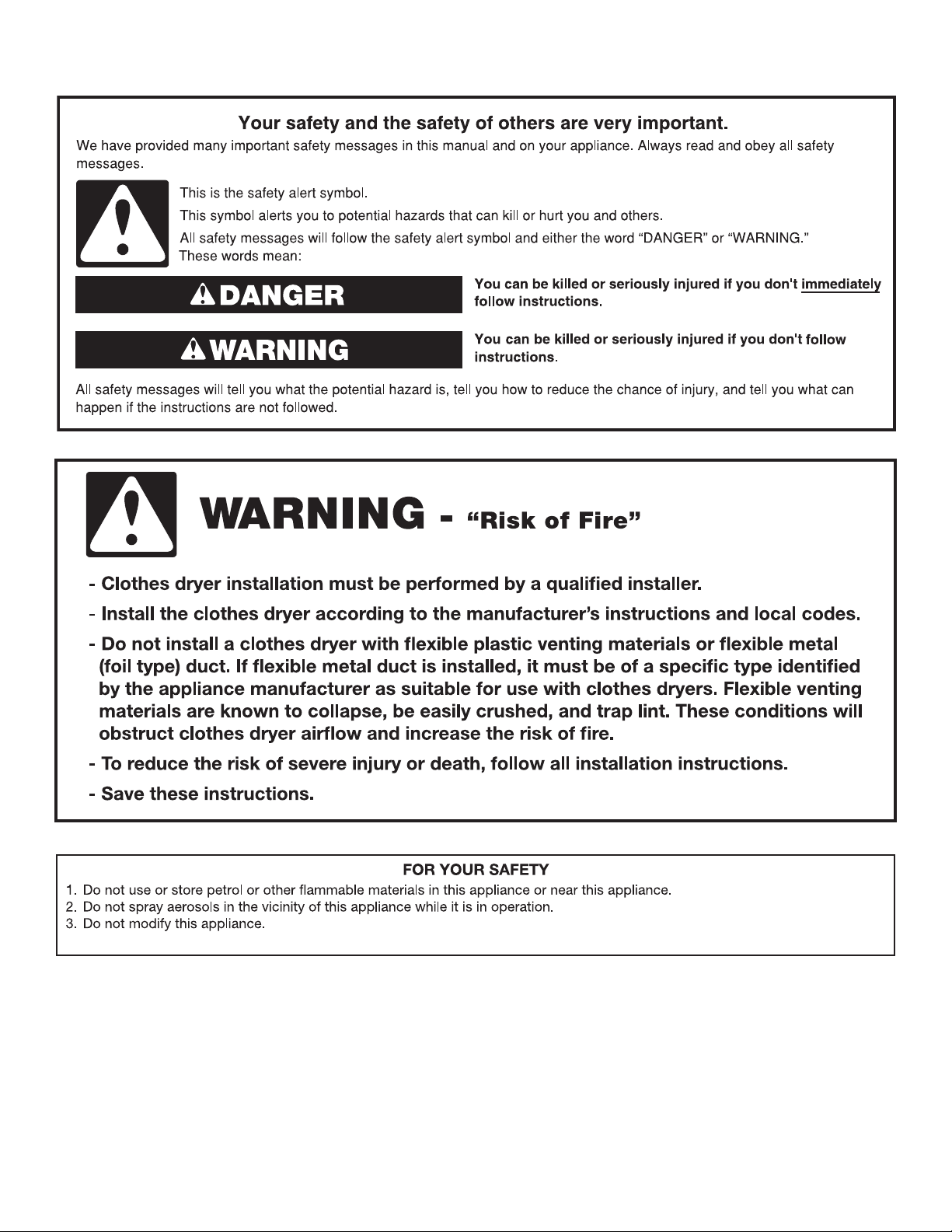
WARNING:
• To reduce the risk of re or suffocation, this dryer MUST BE
EXHAUSTED OUTDOORS.
ADDITIONAL WARNING for Gas Dryers:
• Forced ventilation of fresh air is required. The room
containing the dryer must have an adequate air supply for gas
combustion and drying operation. A window or equivalent
To avoid damaging oor, use a large at piece of cardboard
from dryer carton; place under entire back edge of dryer.
Firmly grasp dryer body (not console panel) and gently lay
dryer down on cardboard.
means of ventilation must be opened in the room when the
dryer is in use (an equivalent form of opening includes an
adjustable louver, hinged panel, or other means of ventilation
that opens directly to outside air).
• If exhaust is connected to a commonly used exhaust system,
it is necessary to install ap valves or alternative adequate
countermeasures at each connection to prevent back ow of
dryer exhaust.
• Exhaust air must not be connected to an exhaust channel of a
furnace.
IMPORTANT: The design of the ue system should ensure that
any condensate formed when operating the appliance is either
retained or subsequently evaporated or discharged. Following
these installation instructions should adequately meet this
requirement.
9

IMPORTANT: Observe all governing codes and ordinances.
A
102 mm
Dryer exhaust must not be connected into any gas vent,
chimney, wall, ceiling, attic, crawlspace, or a concealed space
of a building. Only rigid or exible metal vent shall be used for
exhausting.
(4")
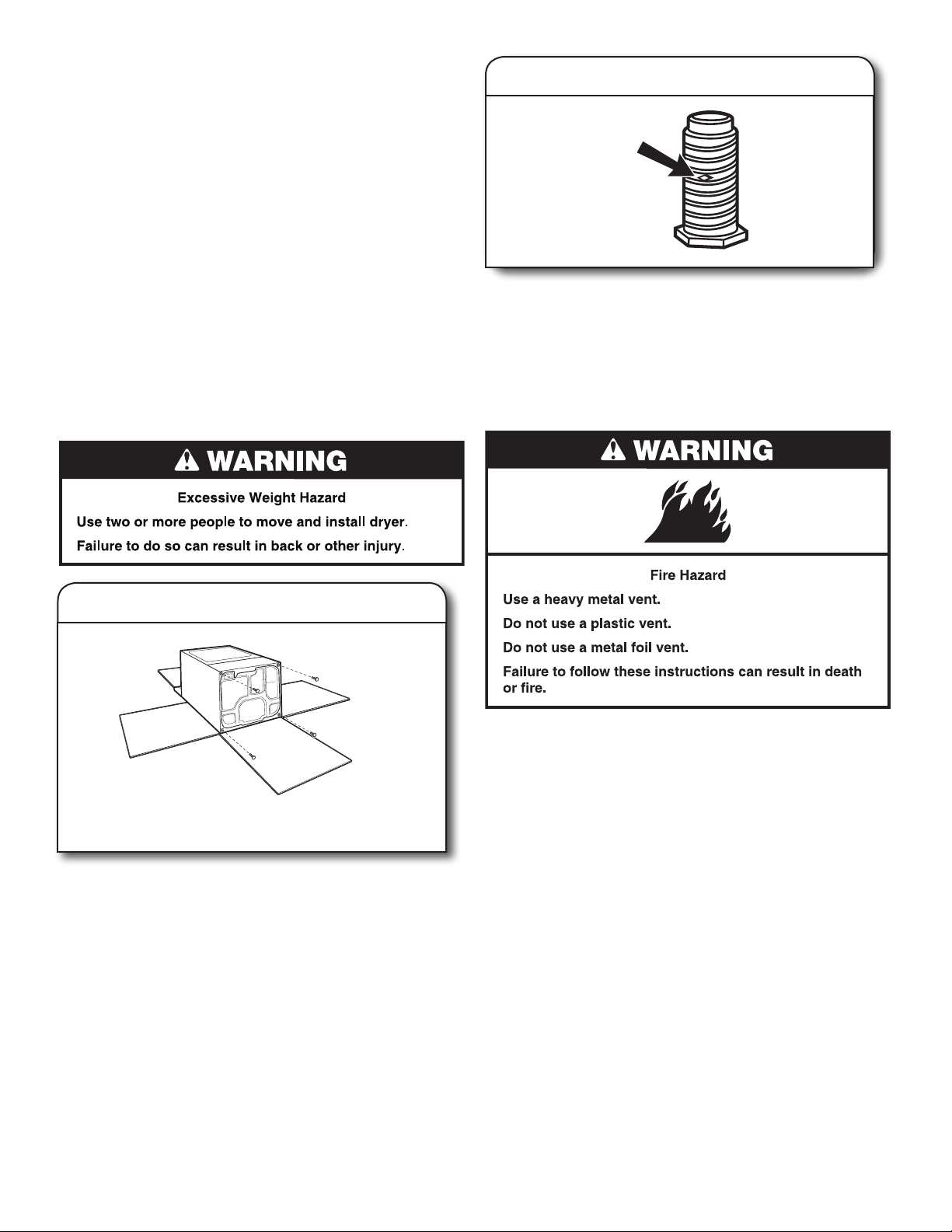
■ Only a 102 mm (4") heavy metal exhaust vent and clamps
may be used. Do not install metal vent that is smaller than
102 mm (4") in diameter.
■ Do not use plastic, non-metal, or metal foil vent
Rigid metal vent
■ Recommended for best drying performance and to avoid
crushing and kinking.
Flexible metal vent: (Acceptable only if accessible to clean)
■ Must be fully extended and supported in nal dryer location.
■ Remove excess exible metal vent to avoid sagging
and kinking that may result in reduced airow and poor
performance.
■ Do not install in enclosed walls, ceilings, or oors.
■ The total length should not exceed 2.4 m (7
3
/4 ft.).
NOTE: If using an existing vent system, clean lint from entire
length of the system and make sure exhaust hood is not
plugged with lint. Replace plastic or metal foil vents with rigid
metal or exible metal vents. Review "Vent System Chart" and
if necessary, modify existing vent system to achieve best drying
performance.
Elbows:
■ 45° elbows provide better airow than 90° elbows.
BetterGood
Clamps:
■ Use clamps to seal all joints.
■ Exhaust vent must not be connected or secured with screws
or other fastening devices that extend into interior of duct
and catch lint. Do not use duct tape.
Exhaust hoods:
Recommended Styles:
Vent products can be purchased from your dealer. For more
information, see “Assistance or Service” section in your “Use and
Care Guide.”
PLAN VENT SYSTEM
The design of the ue system should ensure that any condensate
formed when operating the appliance from cold, is either retained
Louvered Hood
Box Hood
Acceptable Style:
Angled Hood
■ An exhaust hood should cap the vent to keep rodents and
insects from entering the home.
■ Exhaust hood must be at least 305 mm (12") from the ground
or any object that may be in the path of the exhaust (such as
owers, rocks, bushes, or snow line, etc.).
■ Do not use an exhaust hood with a magnetic latch.
10
and subsequently evaporated or discharged. Following these
installation instructions should adequately meet this requirement.
Recommended exhaust installations
Typical installations vent the dryer from the rear of the dryer.
Other installations are possible.
B
C
D
E
F
G
B
H
A. Dryer
B. Elbow
C. Wall
D. Exhaust hood
E. Clamps
F. Rigid metal or exible metal vent
G. Vent length necessary to connect elbows
H. Exhaust outlet

Optional exhaust installations (on some models)
C
D
This dryer can be converted to exhaust out the right side,
left side, or through the bottom. If you prefer, you may
contact your local dealer to have the dryer converted.
Periscope installation
Determine vent path:
■ Select route that will provide straightest and most direct
path outdoors.
■ Plan installation to use fewest number of elbows and turns.
See “Venting Requirements.”
■ When using elbows or making turns, allow as much room
as possible.
■ Bend vent gradually to avoid kinking.
■ Use as few 90° turns as possible.
AB
A. Standard rear offset exhaust installation
B. Left or right side exhaust installation
C. Bottom exhaust installation
Alternate installations for close clearances
Venting systems come in many varieties. Select the type best
for your installation. Two close-clearance installations are shown.
Refer to the manufacturer’s instructions.
Over-The-Top installation (also available with one offset elbow)
Determine vent length and elbows needed for best
drying performance:
■ Use following Vent System Chart to determine type of vent
material and hood combinations acceptable to use.
NOTE: Do not use vent runs longer than those specied
in Vent System Chart. Exhaust systems longer than those
specied will:
■ Shorten life of dryer.
■ Reduce performance, resulting in longer drying times
and increased energy usage.
11
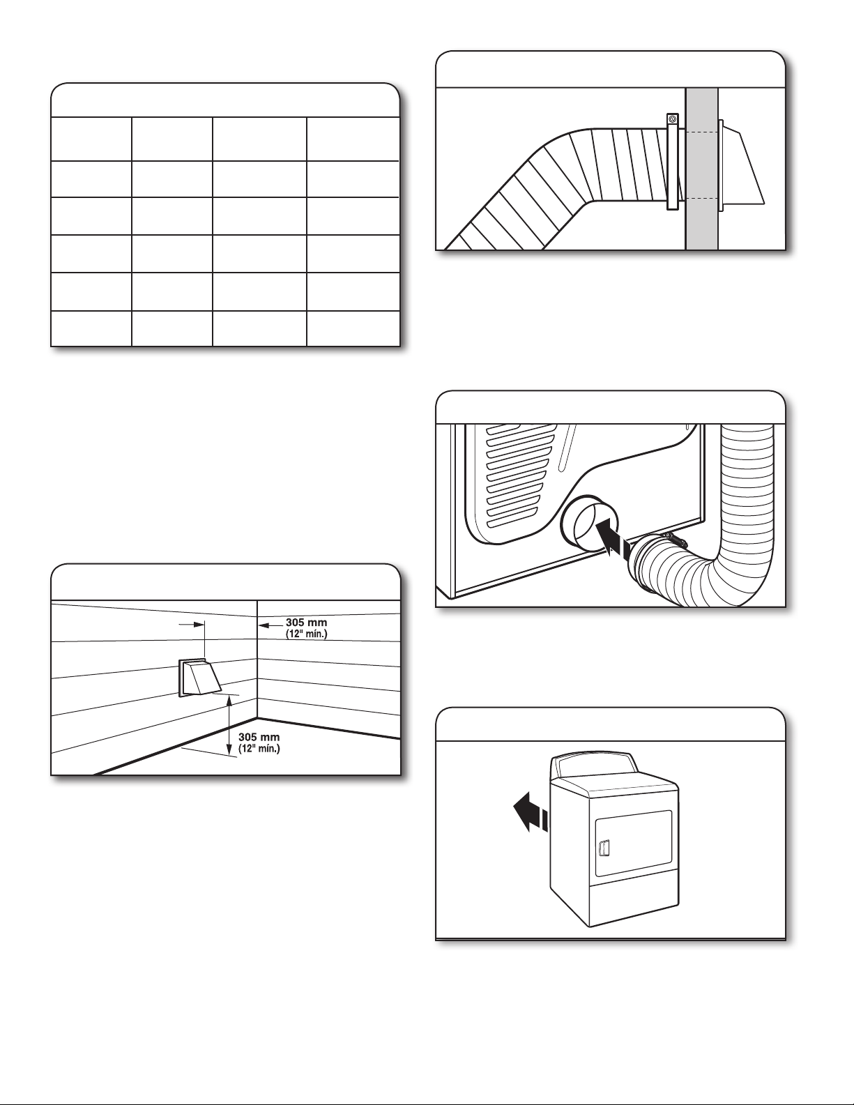
The Vent System Chart provides venting requirements that
will help achieve best drying performance.
Vent System Chart
2.
Connect vent to exhaust hood
Number of
90° turns
or elbows
0
1
2
3
4
NOTE: Side and bottom exhaust installations have a 90° turn
inside the dryer. To determine maximum exhaust length, add
one 90° turn to the chart.
The maximum length using a 51 mm x 152 mm (2"x 6")
rectangular vent with 2 elbows and a 64 mm (2-1/2") exhaust
hood is 2,4 m (8ft).
For exhaust systems not covered by the Vent System Chart (such
as multiple unit hookups, plenums, and power-assist fans), see
Service Manual, Part 603197. (To purchase the Service Manual,
contact your local authorized service dealer.
Type
of vent
Rigid metal
Rigid metal
Rigid metal
Rigid metal
Rigid metal
Box/louvered
hoods
15,8 m (52 ft.)
13,4 m (44 ft.)
11,0 m (36 ft.)
8,2 m (27 ft.)
6,1 m (20 ft.)
Angled
hoods
13,4 m (44 ft.)
11,0 m (36 ft.)
18,5 m (28 ft.)
6,4 m (21 ft.)
4,3 m (14 ft.
Vent must t over the exhaust hood. Secure vent to exhaust
hood with 102 mm (4") clamp. Run vent to dryer location
using straightest path possible. Avoid 90° turns. Use clamps
to seal all joints. Do not use duct tape, screws, or other
fastening devices that extend into interior of vent to secure
vent, because they can catch lint.
CONNECT VENT
1. Connect vent to exhaust outlet
INSTALL VENT SYSTEM
1.
Install exhaust hood
Install exhaust hood and use caulking compound to seal
exterior wall opening around exhaust hood.
Using a 102 mm (4") clamp, connect vent to exhaust outlet
in dryer. If connecting to existing vent, make sure vent is
clean. Dryer vent must t over dryer exhaust outlet and inside
exhaust hood. Check that vent is secured to exhaust hood
with a 102 mm (4") clamp.
2. Move dryer to nal location
12
Move dryer to nal location. Avoid crushing or kinking vent.
After dryer is in place, remove corner posts and cardboard
from under the dryer.
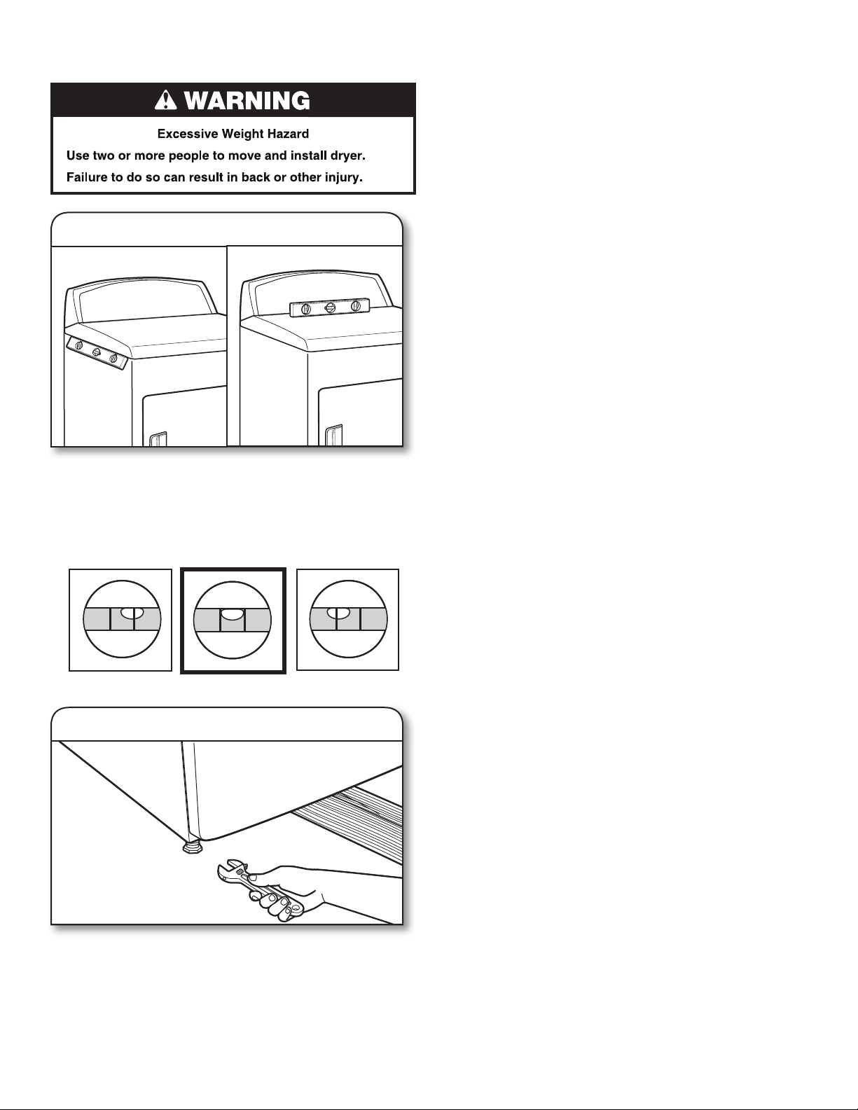
LEVEL DRYER
1. Level Dryer
Check levelness of dryer from side to side. Repeat from
front to back.
NOTE: The dryer must be level to reduce noise and assure
proper performance.
If legs are not long enough to level dryer, order Extended Dryer
Feet kit, Part No. 279810 (sold two legs per kit), from your dealer.
Not Level LEVEL Not Level
1. Tighten and adjust leveling legs
COMPLETE INSTALLATION
CHECKLIST
Check that all parts are now installed. If there is an extra
q
part, go back through steps to see what was skipped.
Check that dryer legs are properly installed.
q
Check that you have all of your tools.
q
Dispose of/recycle all packaging materials.
q
Check dryer’s nal location. Be sure vent is not crushed
q
or kinked.
Secure all exhaust vent joints with 102 mm (4")clamps.
q
For power supply cord installation, plug into an earthed outlet.
q
For direct wire installation, turn on power.
Check that dryer is level. See “Level Dryer”.
q
Remove lm on console and any tape remaining on dryer.
q
Wipe dryer drum interior thoroughly with a damp cloth
q
to remove any dust.
Read “Dryer Use” in your Use and Care Guide.
q
Set the dryer on a full heat cycle (not an air cycle) for
q
20 minutes and start the dryer. (If you have a gas dryer, it is
equipped with an electronic ignition system for the burner
which is fully automatic; no action is needed by the user
(there is no pilot light).
If the dryer will not start, check the following:
■ Controls are set in a running or “On” position.
■ Start button has been pushed rmly.
■ Dryer is plugged into an outlet and/or electrical supply
is on.
■ Household fuse is intact and tight, or circuit breaker has
not tripped.
■ Dryer door is closed.
When the dryer has been running for 5 minutes, open the
q
dryer door and feel for heat. If you feel heat, cancel cycle and
close the door.
If you do not feel heat, turn off dryer, and check the
following:
■ There may be 2 household fuses or circuit breakers for
the dryer. Check that both fuses are intact and tight,
or that both circuit breakers have not tripped. If there
is still no heat, contact a qualied technician.
NOTE: You may notice an odor when the dryer is rst heated.
This odor is common when the heating element is rst used.
The odor will go away.
If dryer is not level, prop up using a wood block, use wrench
to adjust legs up or down, and check again for levelness.
Once legs are level, make sure all four legs are snug against
the ground.
13
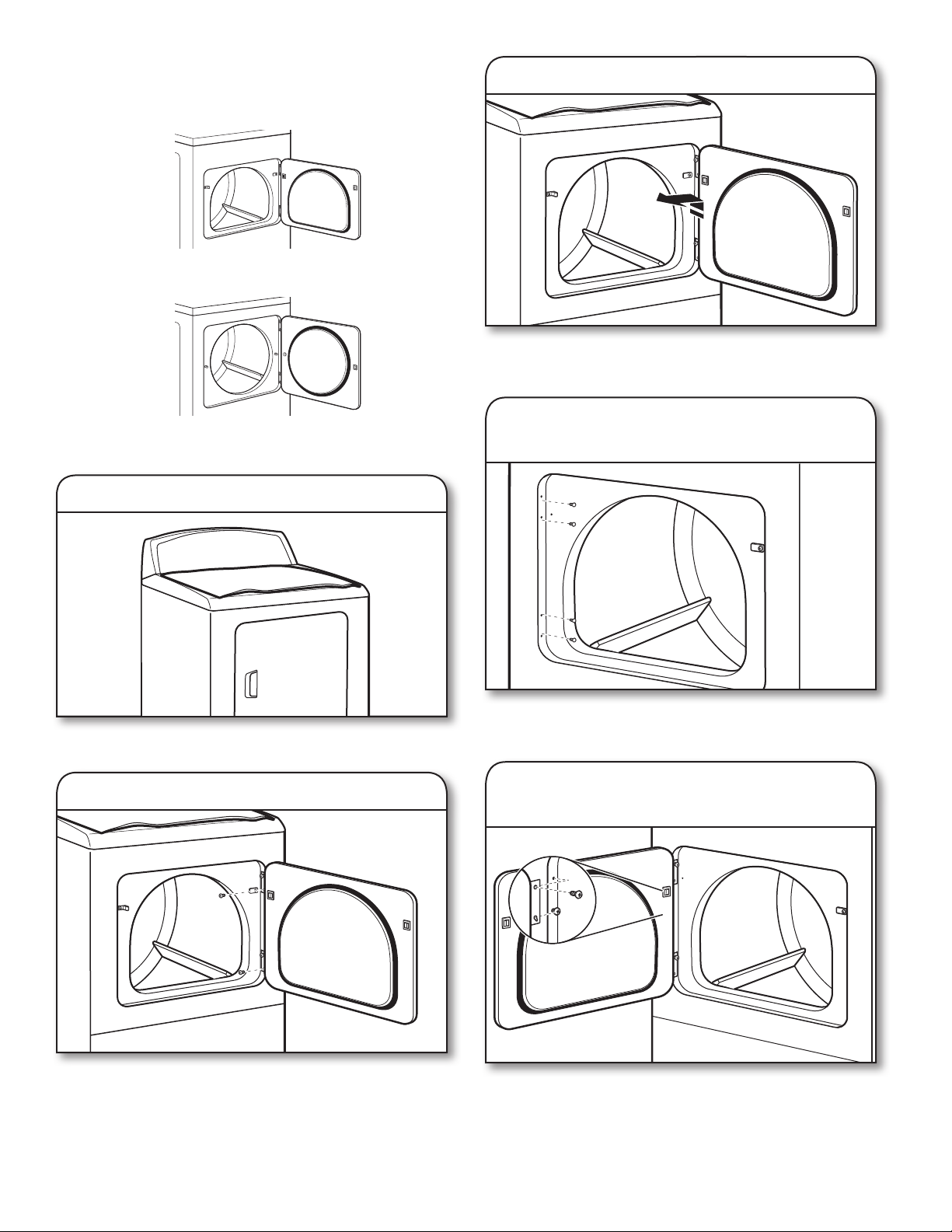
REVERSE DOOR SWING (OPTIONAL)
If your door is the 29" Large Side-Swing Door,
follow steps 1-6.
If your door is the 29" Super Wide Side-Swing Door,
follow steps 1-13.
3. Lift door off top screws
Lift door until top screws in cabinet are in large part of hinge
slot. Pull door forward off screws. Set door on top of dryer.
Remove top screws from dryer cabinet.
NOTE: Magnetized screw driver is helpful.
Large Side-Swing Door
1. Place towel on dryer
Place towel on top of dryer to avoid damaging the surface.
2. Remove bottom screws
4. Remove and transfer hinge
hole plugs
Use a small, at-blade screwdriver to gently remove 4 hinge
hole plugs on left side of dryer cabinet. Insert plugs into hinge
holes on opposite side of dryer cabinet.
5. Insert screws in hinge holes on
dryer cabinet
Open dryer door. Remove bottom screws from dryer cabinet
side of hinges. Loosen (do not remove) top screws from dryer
cabinet side of hinges.
14
NOTE: Two people may be needed to reinstall door.
Insert screws into bottom holes on left side of dryer cabinet.
Tighten screws halfway. Position door so large end of door
hinge slot is over screws. Slide door up so screws are in
bottom of slots. Tighten screws. Insert and tighten top
screws in hinges.
6. Check door strike alignment
3. Lift door off top screws
Close door and check that door strike aligns with door
catch. If needed, slide door catch left or right within slot
to adjust alignment.
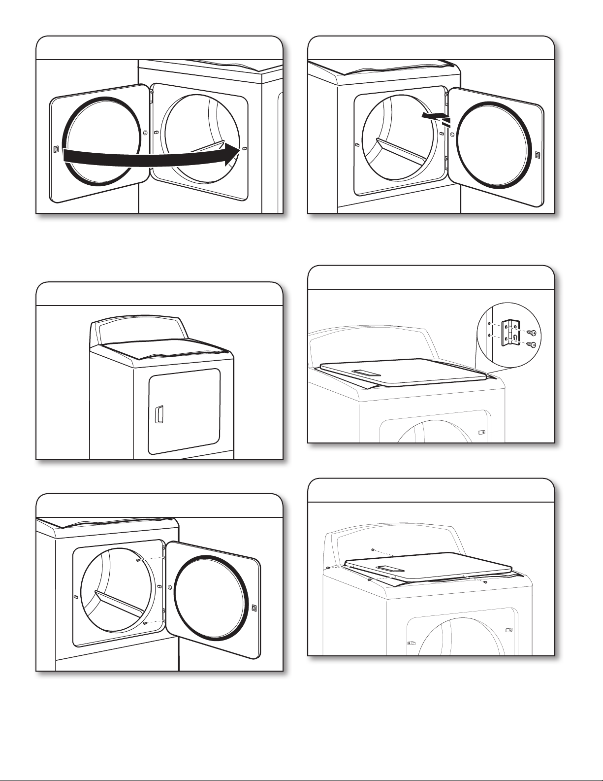
Super Wide Side-Swing Door
1. Place towel on dryer
Place towel on top of dryer to avoid damaging the surface.
2. Remove bottom screws
Lift door until top screws in dryer cabinet are in large part of
hinge slot. Pull door forward off screws. Set door (handle side
up) on top of dryer. Remove top screws from dryer cabinet.
4. Remove screws from hinges
Remove screws attaching hinges to door.
5. Remove screws from door
Open dryer door. Remove bottom screws from dryer cabinet
side of hinges. Loosen (do not remove) top screws from
dryer cabinet side of hinges.
Remove screws at top, bottom, and side of door (4 screws).
Keep door screws separate from hinge screws as they are
different sizes. Holding door over towel on dryer, grasp sides
of outer door and lift to separate it from inner door.
NOTE: Do not pry apart with putty knife or screwdriver.
Do not pull on door seal or plastic door catches.
15

6. Rotate outer door
Take outer door and rotate in 180º and set it back down on
inner door. Be certain to keep cardboard spacer centered
between doors. Reattach outer door panel to inner door
panel so handle is on the side where hinges were just
removed. Insert 4 door screws.
7. Flip door over
9. Remove door strike
Remove door strike from dryer cabinet and set aside.
10. Remove and transfer
hinge hole plugs
Flip door over so handle side is down.
8. Attach door hinges
Use a small, at-blade screwdriver to gently remove 4 hinge
hole plugs on left side of dryer cabinet. Transfer plugs into
hinge holes on opposite side of dryer cabinet.
11. Insert screws in hinge holes on
dryer cabinet
Reattach door hinges to dryer door so that the larger hole is
at the bottom of the hinge.
16
NOTE: Two people may be needed to reinstall door.
Insert screws into the bottom holes on left side of dryer
cabinet. Tighten screws halfway. Position door so large end
of door hinge slot is over screws. Slide door up so screws
are in bottom of slots. Tighten screws. Insert and tighten top
screws in hinges.
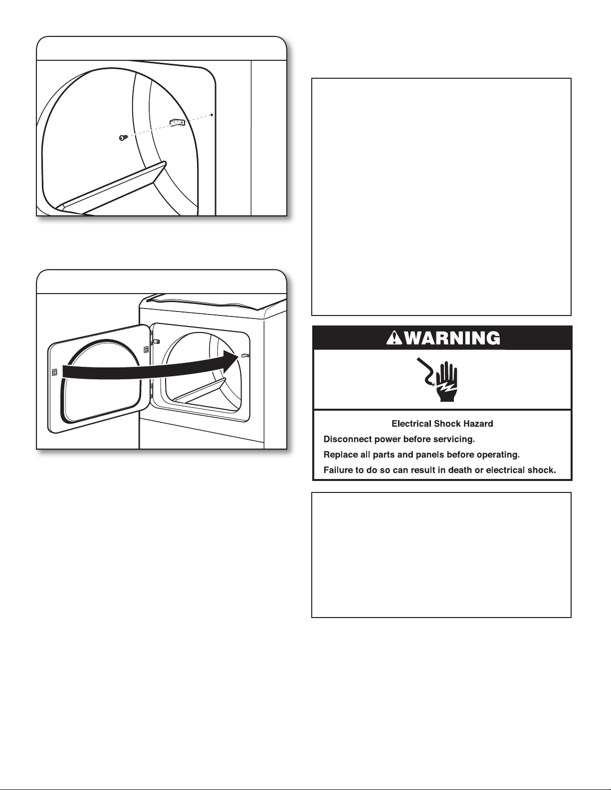
12. Remove door strike plug
Remove door strike plug. Insert the door strike removed in
Step 9 into hole and secure with screw. Insert door strike
plug into original door strike hole and secure with screw.
13. Check door strike alignment
NON-USE, STORAGE,
AND MOVING CARE
Non-Use or Storage Care
Operate your dryer only when you are at home. If you will
be on vacation or not using your dryer for an extended
period of time, you should:
1. Unplug dryer or disconnect power.
2. Clean lint screen. See “Cleaning the Lint Screen.”
Moving Care
For power supply cord-connected dryers:
1. Unplug the power supply cord.
2. Gas models only: Close shut-off valve in gas supply line.
3. Gas models only: Disconnect gas supply line pipe and
remove ttings attached to dryer pipe.
4. Gas models only: Cap the open fuel supply line.
5. Make sure leveling legs are secure in dryer base.
6. Use tape to secure dryer door.
IMPORTANT: Dryer must be transported in the upright
position.
Close door and check that door strike aligns with door
catch. If it is needed, slide door catch left or right within slot
to adjust alignment.
For direct-wired dryers:
1. Disconnect power.
2. Disconnect wiring.
3. Make sure leveling legs are secure in dryer base.
4. Use tape to secure dryer door.
Reinstalling the Dryer
Follow the Installation Instructions to locate, level,
and connect the dryer.
17

TECHNICAL SPECIFICATIONS
220-240V~50Hz 1ph 3A max. IPX4
Maximum Power Absortion/Usage: 4700 Watts Moisture Resistance (Water Ingress, Rain Test): 5500-5600
Factory set for NATURAL GAS: Injector: 2,2 mm Heat input gross: 5,9 kW
European Country:
European Gas Category:
Gas Flow Rate:
Supply Pressure (G20):
Factory Adjusted Pressure:
With LP Gas Conversion Kit: Injector size: 1,25 mm Heat input gross: 6,4 kW
European Country:
European Gas Category:
Butane Supply Pressure (G30):
Adjusted Pressure:
Propane Supply Pressure (G31):
Adjusted Pressure:
With France/Belgium NATURAL GAS conversion kit: Injector size: 1,65 mm Heat input gross: 5,9 kW
European Country:
European Gas Category:
Supply Pressure (G20):
Supply Pressure (G25):
Adjusted Pressure:
Note: Conversion kit: From Natural Gas to LP Gas : Whirlpool Part No. W10233219.
Conversion kit: From Natural Gas to Natural Gas - France/Belgium: Whirlpool Part No. W10181947.
Manufacturer: Whirlpool Corporation, Benton Harbor, Michigan 49022, USA.
CZ, CY, ES, GB, GR, HR, IE, IT,
CZ, CY, ES, GB, GR, HR, IE, IT,
PT, SI, SK, TR
II
2H3+
0.562703 M3/HR
20 mbar
7.4 mbar
PT, SI, SK, TR
II
2H3+
28-30 mbar
N/A
37 mbar
N/A
FR, BE
I
2E+
20 mbar
25 mbar
N/A
CY, CZ, DK, EE, FI, GR, HU, IT,
NO, RO, SE, SK, TR
II
2H3B/P
0.562703 M3/HR
20 mbar
7.4 mbar
CY, CZ, DK, EE, FI, GR, HU, IT,
NO, RO, SE, SK, TR
II
2H3B/P
30 mbar
N/A
30 mbar
N/A
TROUBLESHOOTING
See the “Use and Care Guide” to possibly avoid the cost of a service call.
EU representative: Whirlpool Europe s.r.l., Viale Guido Borghi 27, 21025 Comerio (VA) Italy
Manufacturer: Whirlpool Corp., 1300 Marion-Agosta Rd., Marion, OH 43302
18
SECURITE DU SECHE-LINGE
19
20
Prendre contact avec le propriétaire de la machine pour une intervention et des réparations
correctes si le produit semble endommagé ou défectueux.
21
ELIMINATION DU SECHE-LINGE
EXIGENCES D’INSTALLATION
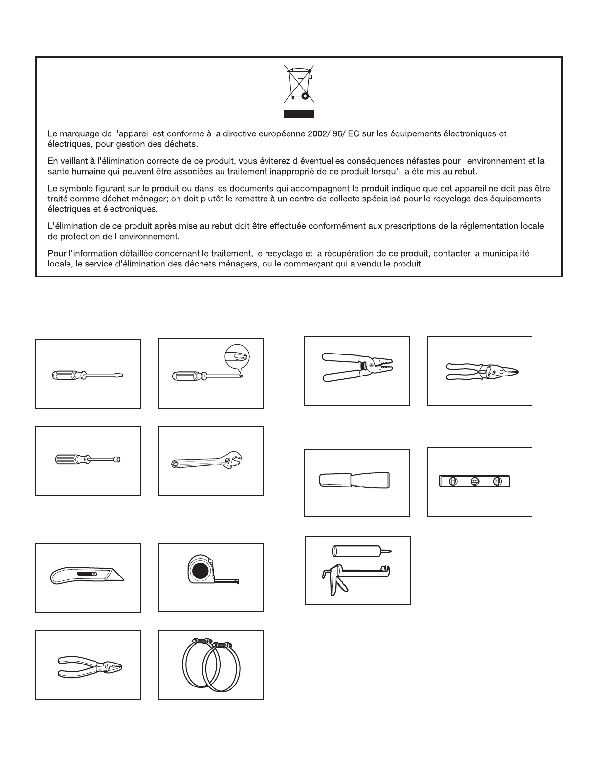
Outillage et Pièces
Rassembler les outils et piéces nécessaires avant de commancer
l’installation.
Tournevis à lame plate Pince à dénuder les ls
Tourne-écrou de 6,2 mm
(1/4")
Couteau utilitaire
Tournevis Phillips no 2
Clé à molette avec ouverture
jusqu’à 25 mm (1") ou clé à
douille hexagonale (pour ajuster
les pieds du sèche-linge)
Mètre ruban
(pour les installations à
raccordement direct)
Couteau à mastic
Pistolet à calfeutrage et
composé de calfeutrage
(pour l’installation
d’un nouveau circuit
d’évacuation)
Cisaille de ferblantier (pour
l’installation d’un nouveau
conduit)
Niveau
Pince
22
Brides de conduit
 Loading...