

Whirlpool 3LTE5243BN0 User Manual
Thin Twin
IMPORTANT:
Read
and save
WasheriDryer
In
Sk
rllation
230 Volt, 50 Hz
sfrucfions
these instructions,
IMPORTANt
Insbller: Leave Installation
Homeowner: Keep Installation lnstr
Save Installation Instructions for locc
with the homeowner,
for
future reference,
electrical inspector’s use.
Instruct’- -
Ions
uctions
31
I
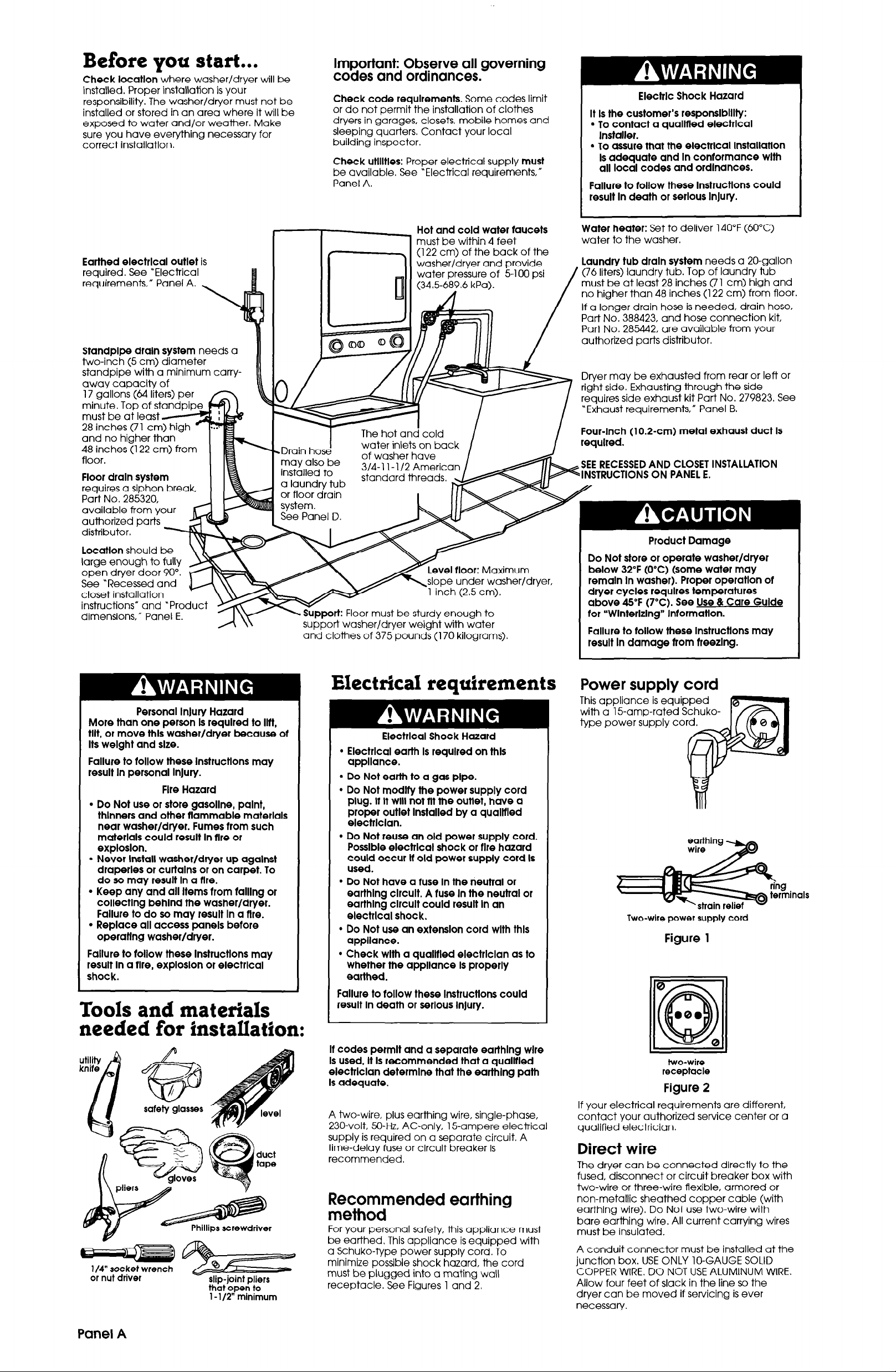
Before you start...
Check locatlon
installed. Proper installation is your
responsibility. The washer/dryer must not be
installed or stored in an area where it will be
exposed to water and/or weather. Make
sure vou have evervthina necessarv for
correct installation. _ -
where washer/dryer will be
Important: Observe all governing
codes and ordinances.
Check code requlrements.
or do not permit the installation of clothes
dryers in garages, closets, mobile homes and
sleeping quarters. Contact your local
building inspector.
Check utllltles:
be available. See *Electrical requirements,”
Panel A.
Proper electrical supply
Some codes limit
must
Electric Shock Hazard
It Is the customer’s responslblllty:
l
To contact a quallfled electrlcal
Installer.
l
To assure that the electrlcal lnstallatlon
Is adequate and In conformance wlth
all local codes and ordinances.
Failure to follow these lnstructlons could
result In death or serlous InJury.
Earthed electrlcal outlet
required. See “Electrical
requirements,” Panel A.
Standplpe draln system
two-inch (5 cm) diameter
standpipe with a minimum carryaway capacity of
must be at lea
and no higher than
48 inches (122 cm) from
floor.
is
needs a
Floor draln system
requires a siphon break,
Part No. 285320,
available from your
authorized parts
distributor.
Locatlon
large enough to fully
open dryer door 90”.
See “Recessed and
closet installation
instructions” and “Pro
dimensions,” Panel E.
should be
Hot and cold water faucets
must be within 4 feet
(122 cm) of the back of the
washer/dryer and provide
water pressure of 5-100 psi
(34.56T.6 kPa).
MI I
The hot and cold /
T
water inlets on back
of washer have
3/4-l l-1/2 Americ
standard threads.
vel tloor:
slope under washer/dryer,
ust be sturdy enough to
dryer weight with water
and clothes of 375 pounds (170 kilograms).
Maximum
Water heater:
water to the washer.
Laundry tub draln system
(76 liters) laundry tub. Top of laundry tub
must be at least 28 inches (71 cm) high and
no higher than 48 inches (122 cm) from floor.
/
If a longer drain hose is needed, drain hose.
Part No. 388423, and hose connection kit,
Part No. 285442, are available from your
authorized parts distributor.
Dryer may be exhausted from rear or left or
right side. Exhausting through the side
requires side exhaust kit Part No. 279823. See
“Exhaust requirements,” Panel B.
Four-Inch (10.2-cm) metal exhaust duct Is
I
Set to deliver 140°F (60°C)
needs a 20-gallon
SEE RECESSED AND CLOSET INSTALLATION
INSTRUCTIONS ON PANEL E.
Product Damage
Do Not store or operate washer/dryer
below 32°F (0%) (some water may
remain In washer). Proper operatlon of
dryer cycles requires temperatures
above 45°F (7°C). See Use & Care Guide
tar “Wlnterlzlng” Intormatlon.
Failure to follow these lnstructlons may
result In damage from freezlng.
More than one person Is required to Ilft,
Personal InJury Hazard
tilt, or move thls washer/dryer because of
Its weight and size.
Failure to tallow these lnstructlons may
result In personal InJury.
Fire Hazard
l
Do Not use or store gasoline, palnt,
thinners and other flammable materials
near washer/dryer. Fumes from such
materials could result In flre or
exploslon.
l
Never Install washer/dryer up agalnst
draperies or curtains or on carpet. To
do so may result In a flre.
l
Keep any and all Items tram falling or
collecting behlnd the washer/dryer.
Failure to do so may result In a flre.
l
Replace all access panels betore
operating washer/dryer.
Failure to follow these lnstructlons may
result In a flre, exploslon or electrlcal
shock.
Tools and materials
needed for fnstaIIation:
l/4” rocket wrench
or
nut
driver
slio-ioint oliers
thbtbpeli to
1 - l/2” mlnimum
Electrical requirements
Electrlcal Shock Hazard
l
Electrlcal earth Is required on thls
appliance.
l
Do Not earth to a gas pipe.
l
Do Not modify the power supply cord
plug. It It will not Ilt the outlet, have a
proper outlet Installed by a qualltled
electrlclan.
l
Do Not reuse an old power supply cord.
Possible electrlcal shock or tire hazard
could occur It old power
used.
l
Do Not have a ruse In the neutral or
earthlng clrcult. A ruse In the neutral or
earthlng clrcult could result In an
electrlcal shock.
l
Do Not use an extension cord wlth thls
appliance.
l
Check wlth a quallfled electrlclan as to
whether the appliance Is properly
earthed.
Failure to follow these lnstructlons could
result In death or serious InJury.
It codes permit and a separate earthlng wire
Is used, It Is recommended that a quallfled
electrlclan determlne that the earthlng path
Is adequate.
A two-wire, plus earthing wire, single-phase,
230-volt, %-Hz, AC-only, 15-ampere electrical
supply is required on a separate circuit. A
time-delay fuse or circuit breaker is
recommended.
Recommended earthing
method
For your personal safety, this appliance must
be earthed. This appliance is equipped with
a Schuko-type power supply cord. To
minimize possible shock hazard, the cord
must be plugged into a mating wall
receptacle. See Figures 1 and 2.
supply
cord Is
Power supply cord
This appliance is equipped
with a 15-amp-rated Schukotype power supply co
Two-wire power supply cord
Figure 1
0
000
Iail
two-wire
receptacle
0
Figure 2
If your electrical requirements are different,
contact your authorized service center or a
qualified electrician.
Direct wire
The dryer can be connected directly to the
fused, disconnect or circuit breaker box with
two-wire or three-wire flexible, armored or
non-metallic sheathed copper cable (with
earthing wire). Do Not use two-wire with
bare earthing wire. All current carrying wires
must be
A conduit connector must be installed at the
junction box. USE ONLY lo-GAUGE SOLID
COPPER WIRE. DO NOT USE ALUMINUM WIRE.
Allow four feet of slack in the line so the
dryer can be moved if servicing is ever
necessary.
insulated.
Panel A
Exhaust reauirements
Fire Hazard
. Do Not use non-metal, tlexlble duct.
l
Do Not use metal duct smaller than
4 Inches (10.2 cm) In diameter.
. Do Not use exhaust hoods wlth
magnetic latches.
l
Check that exhaust system Is not longer
than specltled. Exhaust systems longer
than specltled will:
- Accumulate Ilnt.
- Shorten the llte ot the product.
- Reduce performance and result In
longer drylng times and Increased
energy usage.
Failure to
a tlre.
l
Do Not exhaust the dryer Into a
chimney, turnace cold alr duct, attlc or
crawl space, or any other duct used tar
ventlng.
l
Clean the exhaust system every year.
Accumulated llnt could be tuel tar a tlre or
cause molsture damage.
l
Exhaustlng your dryer Indoors Is Not
recommended. The molsture and llnt
Indoors may cause:
- Lint to gather lnslde and around the
- Moisture damage to woodwork,
- Housecleanlng problems and possible
Failure to tallow these lnstructlons could
result In tire damage, personal InJury or
health problems.
If uslng an exlstlng exhaust system, clean llnt
tram entlre length of exhaust system. Make
sure exhaust hood Is not plugged wlth Ilnt.
The exhaust system should be Inspected and
cleaned yearly.
Replace any vlnyl or metalllzed plastic toll
exhaust duct wlth rlgld metal or tlexlble
metal duct.
Use duct tape
joints. Do Not use screws
to secure duct.
Four-Inch (10.2 cm) rlgld
metal pipe
Plan installation to use
the fewest number of
elbows and turns.
Metal tlexlble duct
and supported when the dryer is in its final
position. DO NOT KINK OR CRUSH THE DUCT.
The metal tlexlble duct must be tully
extended to allow adequate exhaust alr to
ri0w.
Allow as much room as possible when using
elbows or making turns. Bend duct gradually
to avoid kinking. Remove excess flexible
duct to avoid sagging and kinking that may
result in reduced air flow.
The exhaust duct
be routed up, down,
left, right or straight out
the back of the
washer/dryer. Space
requirements are
provided on Panel E
and on the rear panel
of the washer/dryer. Use
the straightest path
possible to avoid 90
turns.
r0ii0w
speclrlcatlons may result In
dryer and be a fuel tar tlre.
furniture, palnt, wallpaper, carpet, etc.
health problems.
to seal all
exhaust air flow
better
is preferred.
I-I
must be fully extended
can
good
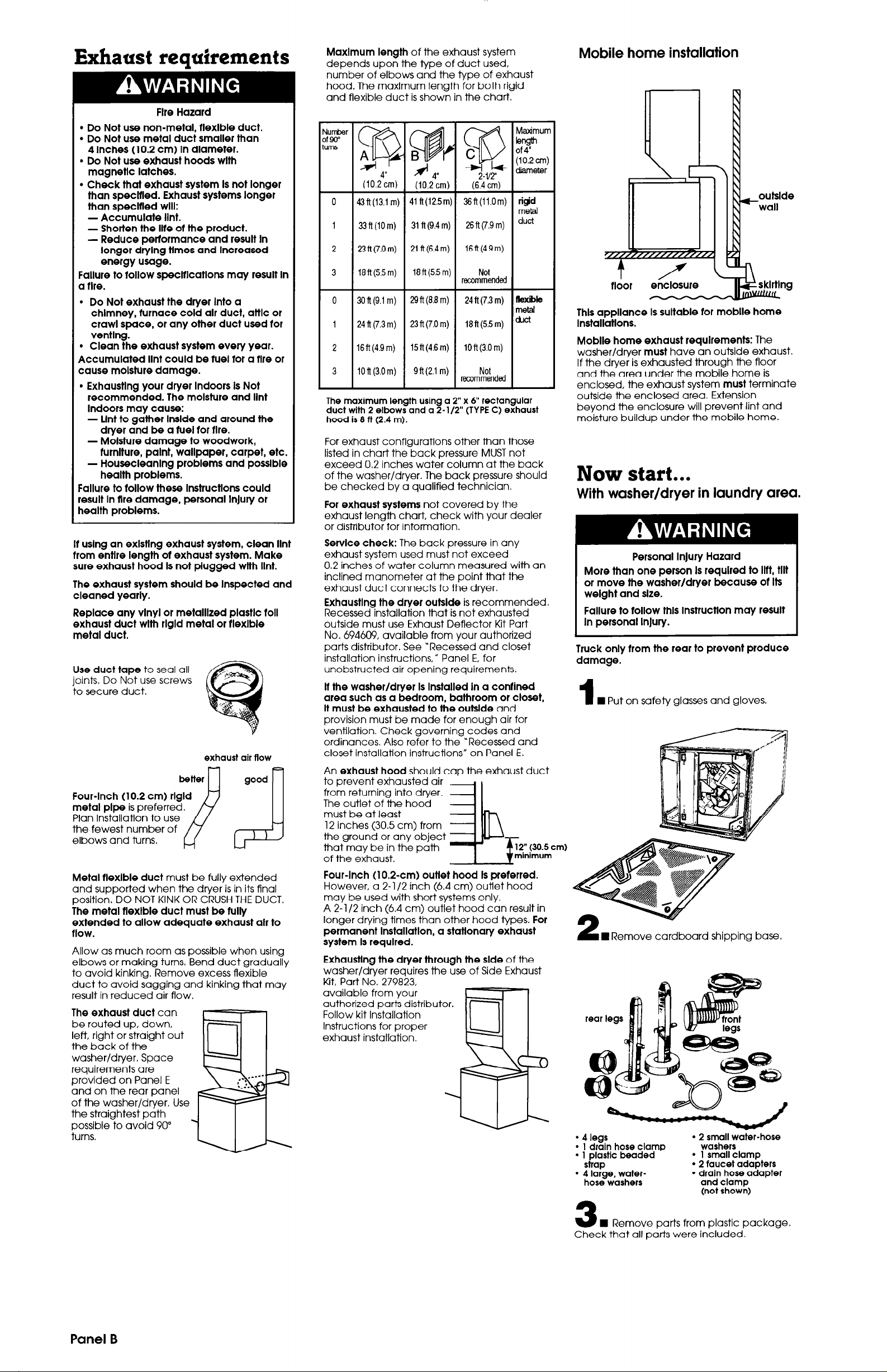
Maxlmum length
depends upon the type of duct used,
number of elbows and the type of exhaust
hood. The maximum length for both rigid
and flexible duct is shown in the chart.
(dcm)
~~ft(i3.1
0
1
33ft(iOm)
2 23 ft (7.0
Wft(55m)
3
0 3Oft(9.1 m)
1 24 ft (7.3 m)
lSft(4.9 m)
2
3
iOft(3,Om)
The maximum length using a 2” x 6” rectangular
duct with 2 elbows and a 2-l/2” (TYPE C) exhaust
hood is 8 ft (2.4 m).
For exhaust configurations other than those
listed in chart the back pressure MUST not
exceed 0.2 inches water column at the back
of the washer/dryer. The back pressure should
be checked by a qualified technician.
For exhaust systems
exhaust length chart, check with your dealer
or distributor for information.
Service check:
exhaust system used must not exceed
0.2 inches of water column measured with an
inclined manometer at the point that the
exhaust duct connects to the dryer.
Exhaustlng the dryer ouklde
Recessed installation that is not exhausted
outside must use Exhaust Deflector Kit Part
No. 694609, available from your authorized
parts distributor. See “Recessed and closet
installation instructions,” Panel E, for
unobstructed air opening requirements.
of the exhaust system
d4”
(10.2
cm)
m) 41 ft(l2.5m) 36ft(ii.Om) ridd
31 ft (9.4 m) 26ft(7.9m)
21 ft (6.4 m) 16ft(4.9m)
m)
lSft(5.5 m)
29ft(8.8m)
23ft(7.0m) 18ft(5.5m) *’
15ft(4.6m)
gft(2.1 m) Not
not covered by the
The back pressure in any
2-W
(6.4 cm)
Not
recommended
24ft(73m) flexible
lOft(3.0m)
recommended
is recommended.
d!arneter
meti
duct
metal
It the washer/dryer Is Installed In a confined
area such as a bedroom, bathroom or closet,
It must be exhausted to the outslde
provision must be made for enough air for
ventilation. Check governing codes and
ordinances. Also refer to the “Recessed and
closet installation instructions” on Panel E.
An
exhaust hood
to prevent exhausted air
from returning into dryer.
The outlet of the hood
must be at least
12 inches (30.5 cm) from
the ground or any object
that may be in the path
of the exhaust.
should cap the exhaust duct
!l!!!r
and
12” (30.5 cm)
minimum
Four-Inch (10.2~cm) outlet hood Is preferred.
However, a 2-l/2 inch (6.4 cm) outlet hood
may be used with short systems only.
A 2- l/2 inch (6.4 cm) outlet hood can result in
longer drying times than other hood types.
For
permanent Installation, a statlonary exhaust
system Is required.
Exhaustlng the dryer through the slde
washer/dryer requires the use of Side Exhaust
Kit, Part No. 279823,
available from your
authorized parts distributor.
Follow kit Installation
Instructions for proper
exhaust installation.
of the
Mobile home installation
outslde
wall
rldor
Thls appliance Is sultable tar moblle home
Installations.
Moblle home exhaust requlrements:
washer/dryer
If the dryer is exhausted through the floor
and the area under the mobile home is
enclosed, the exhaust system
outside the enclosed area. Extension
beyond the enclosure will prevent lint and
moisture buildup under the mobile home.
must
have an outside exhaust.
must
The
terminate
Now start...
With washer/dryer in laundry area.
Personal Injury Hazard
More than one person Is required to Iltt, tilt
or move the washer/dryer because ot Its
welght and size.
Failure to follow thls InstructIon may result
In personal Injury.
Truck only tram the rear to prevent produce
damage.
n Put on safety glasses and gloves.
1
W Remove cardboard shipping base.
A
l
l
4
legs
l
I drain hose clamp
l
1 plastic beaded
strap
l
4 large, water-
hose washers
2 small water-hose
washers
l
1 small clamp
l
2 faucet adapters
* drain hose adapter
and clamp
(not shown)
Panel B
W Remove parts from plastic package.
3
Check that all parts were included.
 Loading...