

Whirlpool 3LCHW9100YQ Installation Instructions
INSTALLATION INSTRUCTIONS
SEMI-PRO FRONT-LOAD WASHER
ORIGINAL INSTRUCTIONS
INSTRUCTIONS D’INSTALLATION
LAVE-LINGE SEMI-PRO A CHARGEMENT FRONTAL
TRADUCTION DES INSTRUCTIONS D’ORIGINE
INSTRUCCIONES DE INSTALACIÓN
LAVADORA SEMIPROFESIONAL DE CARGA FRONTAL
TRADUCCIÓN DE LAS INSTRUCCIONES ORIGINALES
ISTRUZIONI D’INSTALLAZIONE
LAVATRICE SEMI-PRO A CARICAMENTO FRONTALE
TRADUZIONE DELLE ISTRUZIONI ORIGINALI
INSTALLATIONSANLEITUNG
FRONTLOADER-WASCHMASCHINE FÜR DEN HÄUFIGEN GERBRAUCHÜBER-
SETZUNG DER ORIGINAL-BEDIENUNGSANLEITUNG
Table of Contents/Table des matières/Índice/Sommario/Inhaltsverzeichnis....................................................2
Model/Modèle/Modelo/Modello/Modell
3LCHW9100YQ
W10353863B
1

TABLE OF CONTENTS
ÍNDICE
WASHER SAFETY ........................................................................ 2
WASHER DISPOSAL ....................................................................4
INSTALLATION REQUIREMENTS ............................................... 4
Tools and Parts ...................................................................... 4
Options ................................................................................... 5
Location Requirements .......................................................... 5
Drain System .......................................................................... 6
Electrical Requirements .........................................................6
INSTALLATION INSTRUCTIONS ................................................. 7
Remove Transport System ..................................................... 7
Power Cord Installation .......................................................... 8
Connect the Inlet Hoses ......................................................... 8
Connect the Drain Hose ......................................................... 9
Secure the Drain Hose ........................................................ 10
Level the Washer ................................................................. 10
Complete Installation .......................................................... 10
CONTROL SET-UP INSTRUCTIONS......................................... 11
General Information .............................................................. 11
Control Set-up Procedures ..................................................11
Set-up Codes ....................................................................... 12
Washer Diagnostic Mode ..................................................... 12
WASHER CARE .......................................................................... 14
Cleaning Your Washer .......................................................... 14
Water Inlet Hoses ................................................................. 14
ASSISTANCE OR SERVICE ....................................................... 14
Accessories .......................................................................... 14
DECLARATION OF CONFORMITY ........................................... 15
SEGURIDAD DE LA LAVADORA ............................................... 29
ELIMINACIÓN DE LA LAVADORA ............................................ 30
REQUISITOS DE INSTALACIÓN ............................................... 30
Herramientas y piezas .......................................................... 30
Opciones .............................................................................. 31
Requisitos de ubicación ....................................................... 31
Sistema de desagüe ............................................................ 32
Requisitos eléctricos ............................................................ 32
INSTRUCCIONES DE INSTALACIÓN ....................................... 33
Eliminación del sistema protector de transporte .................33
Instalación del cable de suministro de energía .................... 34
Conexión de las mangueras de entrada .............................. 34
Conexión de la manguera de desagüe ................................ 35
Fijación de la manguera de desagüe .................................. 36
Nivelación de la lavadora .................................................... 36
Complete la instalación ....................................................... 36
INSTRUCCIONES DE PROGRAMACIÓN DEL CONTROL ...... 37
Información general ............................................................. 37
Procedimientos de programación del control ...................... 37
Códigos de programación ...................................................38
Modo de diagnóstico de la lavadora .................................... 39
CUIDADO DE LA LAVADORA ................................................... 40
Cómo limpiar su lavadora .................................................... 40
Mangueras de entrada de agua ........................................... 40
AYUDA O SERVICIO TÉCNICO ................................................. 41
Accesorios ........................................................................... 41
TABLE DES MATIERES
SECURITE DU LAVE-LINGE ......................................................16
MISE AU REBUT DU LAVE-LINGE ...........................................17
EXIGENCES D’INSTALLATION ................................................. 17
Outillage et pièces ................................................................ 17
Options ................................................................................. 18
Exigences d’emplacement ................................................... 18
Système de vidange ............................................................. 19
Spécications électriques .................................................... 19
INSTRUCTIONS D’INSTALLATION ........................................... 20
Dépose du système de transport ......................................... 20
Installation du cordon d’alimentation ................................... 21
Raccordement des tuyaux d’arrivée d’eau .......................... 21
Raccordement du tuyau de vidange .................................... 22
Immobilisation du tuyau de vidange ................................... 23
Réglage de l’aplomb du lave-linge ...................................... 23
Achever l’installation ........................................................... 23
INSTRUCTIONS DE PARAMÉTRAGE DU MODULE
DE COMMANDE ........................................................................ 24
Informations générales ......................................................... 24
Procédures de réglage des systèmes de commande .......... 24
Codes de paramétrage ........................................................ 25
Mode de diagnostic du lave-linge ........................................ 26
ENTRETIEN DU LAVE-LINGE ...................................................27
Nettoyage du lave-linge ....................................................... 27
Tuyaux d’arrivée d’eau ......................................................... 28
ASSISTANCE OU SERVICE ....................................................... 28
Accessoires .......................................................................... 28
SOMMARIO
SICUREZZA DELLA LAVATRICE ..............................................42
SMALTIMENTO DELLA LAVATRICE ......................................... 43
REQUISITI D’INSTALLAZIONE ................................................. 43
Attrezzi e componenti ..........................................................43
Opzioni ................................................................................. 44
Requisiti di posizionamento ................................................. 44
Sistema di scarico ................................................................ 45
Requisiti elettrici ................................................................... 45
ISTRUZIONI D’INSTALLAZIONE ............................................... 46
Rimozione del sistema di trasporto......................................46
Installazione del cavo di alimentazione ................................ 47
Collegamento dei tubi .......................................................... 47
Collegamento del tubo di scarico ........................................ 48
Fissaggio del tubo di scarico .............................................. 49
Livellamento della lavatrice ................................................. 49
Installazione completa .........................................................49
ISTRUZIONI PER L’UTENTE E DI CONFIGURAZIONE ........... 50
Informazioni di carattere generale ........................................50
Procedure di congurazione dei comandi ...........................50
Codici di congurazione.......................................................51
Modalità diagnostica della lavatrice ..................................... 52
MANUTENZIONE DELLA LAVATRICE ...................................... 53
Pulizia della lavatrice ............................................................ 53
Tubi di ingresso dell’acqua ................................................... 53
ASSISTENZA O MANUTENZIONE ............................................ 54
Accessori .............................................................................. 54
2
INHALTSVERZEICHNIS
GERÄTESICHERHEIT ................................................................ 55
ENTSORGUNG DER WASCHMASCHINE ................................56
INSTALLATIONSVORAUSSETZUNGEN ................................... 56
Werkzeug und Zuebehör ...................................................... 56
Optionen ............................................................................... 57
Standortvoraussetzungen .................................................... 57
Ablaufsystem ........................................................................ 58
Netzanschluss ...................................................................... 58
INSTALLATIONSANLEITUNG .................................................... 59
Entfernung der Transportsicherung...................................... 59
Montage des Netzsteckers .................................................. 60
Anschluss der Zulaufschläuche ........................................... 60
Den Ablaufschlauch anschließen ......................................... 61
Sicherung des Ablaufschlauchs .......................................... 62
Ausrichten der Waschmaschine ...........................................62
Abschluss der Installation ................................................... 62
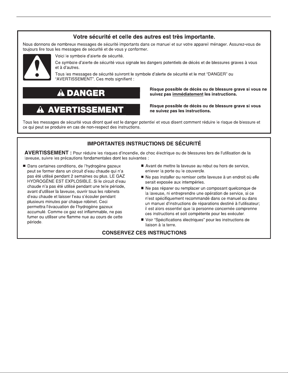
WASHER SAFETY
PROGRAMMIERUNGSANLEITUNG ......................................... 63
Allgemeine Hinweise ............................................................ 63
Programmieren der Waschmaschine ...................................63
Einstellcodes ........................................................................ 64
Diagnosemodus der Waschmaschine ..................................65
PFLEGE UND WARTUNG DER WASCHMASCHINE ...............66
Reinigung der Waschmaschine ............................................66
Zulaufschläuche ................................................................... 67
REPARATUR- UND KUNDENDIENST ...................................... 67
Zusätze ................................................................................. 67
3
AB
DE
Model Nomenclature
3L – Voltage 230v/50Hz plug code
CHW – Commercial Horizontal Washer
91 – Model Type number
WASHER DISPOSAL
INSTALLATION REQUIREMENTS
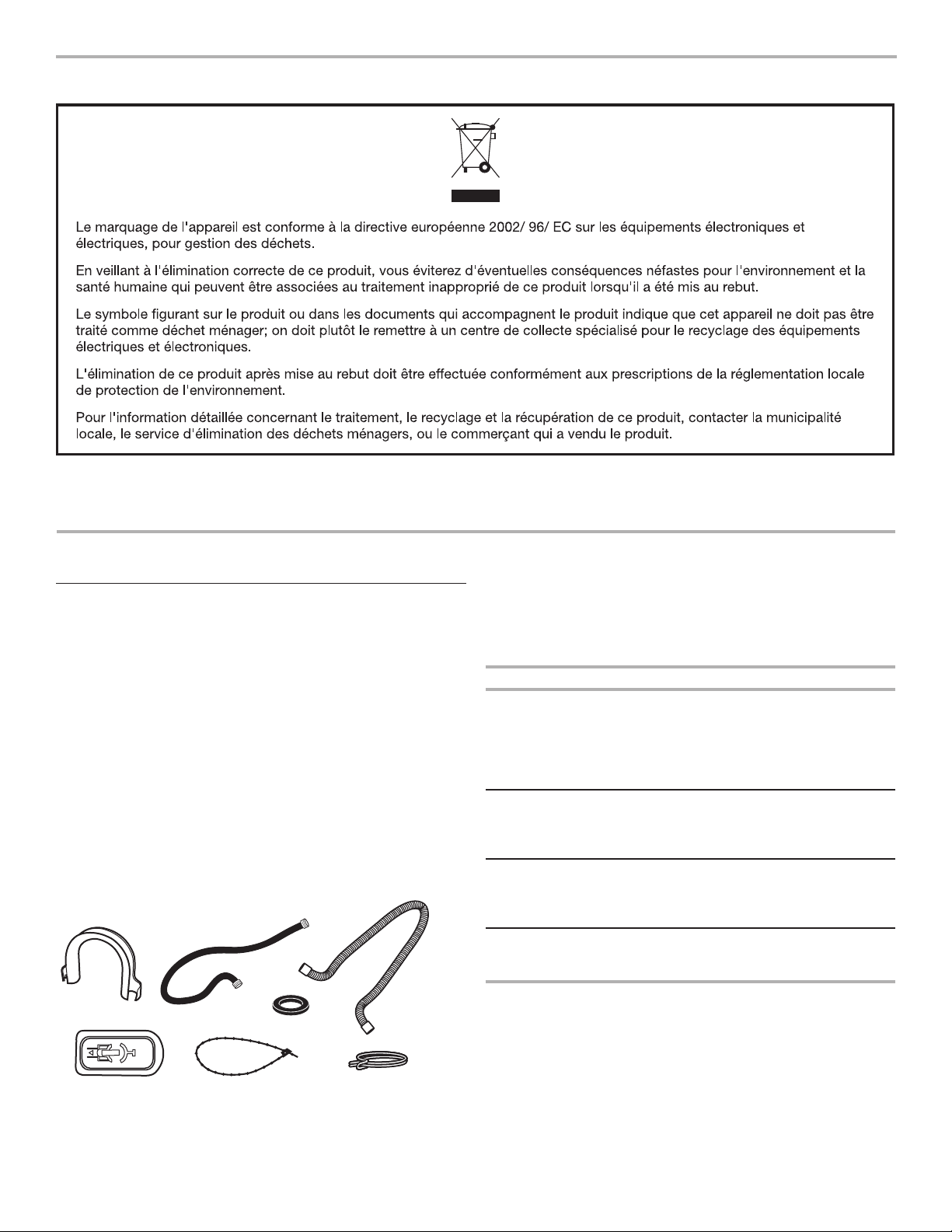
Tools and Parts
Gather the required tools and parts before starting
installation.The parts supplied are in the washer drum.
Tools needed for connecting the water inlet hoses:
■ Pliers (that open to 39.5 mm [1
■ Flashlight (optional)
Tools needed for installation
■ Open-end wrenches 1/2" and 9/16"
®†
■ Torx
■ 1/4" nut driver
■ Level
■ Wood block
■ Ruler or measuring tape
T-20 Security screwdriver
Parts supplied
9
⁄16"])
C
F
Alternate Parts
Your installation may require additional parts. If you are interested
in purchasing one of the items listed here, contact your
authorized Whirlpool distributor.
If You Have You Will Need to Buy
Laundry tub or
Sump pump system (if not already available)
standpipe taller
than 2.4 m (96")
Overhead sewer Standard 76 L (20 gal. ), 762 mm (30") tall
drain tub or utility sink and sump pump
(available from local plumbing suppliers)
Floor drain Siphon break, Part Number 285320;
additional drain hose, Part Number 8318155;
and Floor drain kit, Part Number 280129
Drain hose
too short
1.2 m (4 ft.) drain hose extension kit,
Part Number 285834
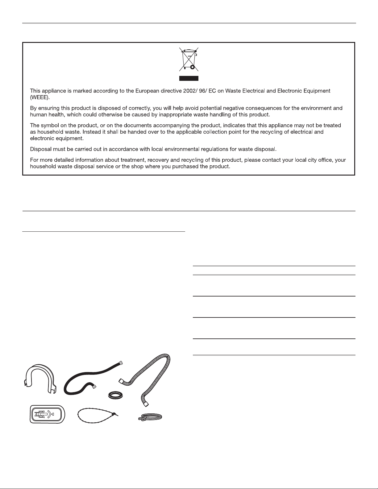
A. U-shaped hose form D. Transit bolt hole plug (4)
B. Water inlet hoses (2) E. Beaded tie strap
C. Inlet hose washers (4) F. Drain hose
G. Hose clamp
†® TORX is a registered trademark of Saturn Fasteners, Inc.
4
G
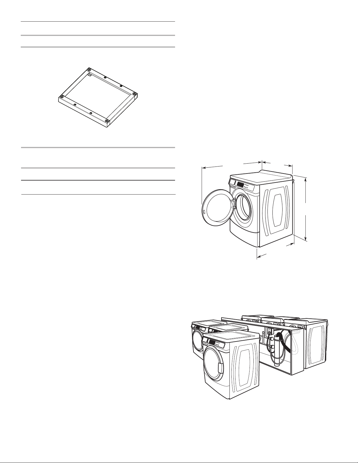
Options
686 mm
Pedestal
You have the option of purchasing pedestals separately for this
washer. The pedestal will add to the total height of the washer.
Installation clearances
■ The location must be large enough to allow the washer door
to be fully opened.
■ Additional spacing should be considered for ease of
installation and servicing. The door opens more than 90°
and it is not reversible.
■ Additional clearances might be required for wall, door, and
oor moldings.
■ Additional spacing of 25 mm (1") on all sides of the washer
is recommended to reduce noise transfer.
■ Companion appliance spacing should also be considered.
■ Removal of mains plug provides the function of an emergency
stop control. When installed, the mains plug must be visible
and accessible to the user for washer disconnection from
the mains supply.
Optional pedestal
Pedestal
Height
Approximate
height with
Color Part Number
washer
(73 mm) 27/8" (1207 mm) 47.5" White WHP0400VW
Location Requirements
Selecting the proper location for your washer improves
performance and minimizes noise and possible washer “walk.”
Your washer can be installed under a custom counter, or in a
basement, laundry room, or recessed area. See “Drain System.”
Companion appliance location requirements should also be
considered. Proper installation is your responsibility.
You will need
■ A water heater set to deliver 60°C (140°F) water to the washer.
■ An earthed electrical outlet located within 1.8 m (6 ft.) of
where the power cord is attached to the back of the washer.
See “Electrical Requirements.”
■ Hot and cold water taps located within 1.2 m (4 ft.) of the hot
and cold water ll valves, and water pressure of 137.9–689.6
kPa (20–100 psi).
■ A level oor with a maximum slope of 25 mm (1") under entire
washer. Installing the washer on soft oor surfaces, such as
carpets or surfaces with foam backing, is not recommended.
■ A sturdy and solid oor to support the washer with a total
weight (water and load) of 180 kg (400 lbs).
Do not operate your washer in temperatures below 0°C (32°F).
Some water can remain in the washer and can cause damage
in low temperatures.
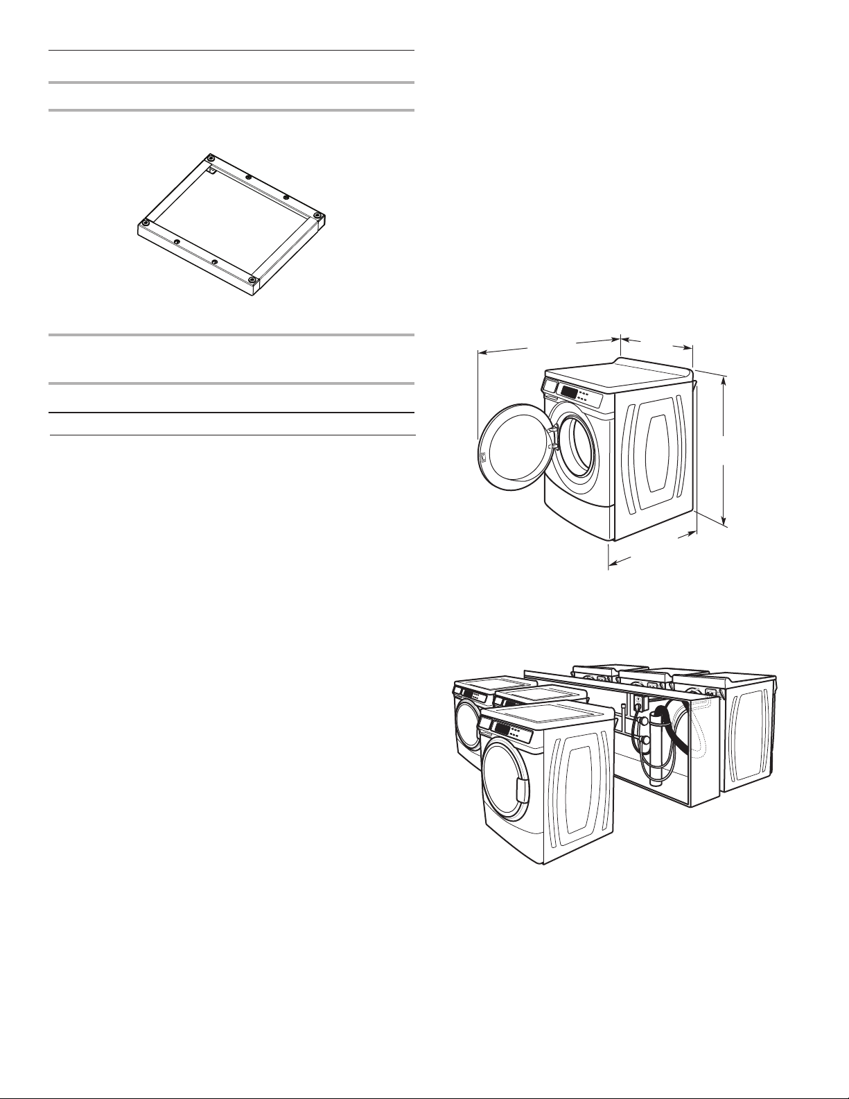
Washer Dimensions
1282 mm
1
(50
/2")
Door is not reversible.
(27")
732 mm
13
/16")
(28
961 mm
5
(37
/6")
A oor drain should be provided under the bulkhead.
Prefabricated bulkheads with electrical outlets, water inlet lines,
and drain facilities should be used only where local codes permit.
5
Drain System
The washer can be installed using the standpipe drain system
(oor or wall), the laundry tub drain system, or the oor drain
system. Select the drain hose installation method you need.
See “Tools and Parts.”
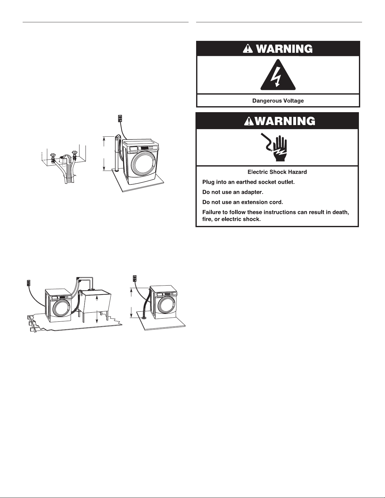
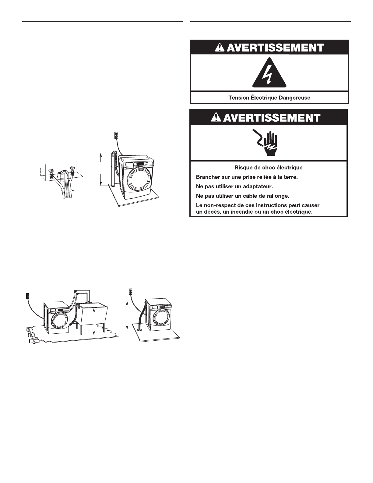
Standpipe drain system – wall or oor (views A & B)
The standpipe drain requires a minimum diameter standpipe of
50 mm (2"). The minimum carry-away capacity can be no less
than 45.5 L (12 gal.) per minute.
The top of the standpipe must be at least 762 mm (30") high and
no higher than 2.4 m (96") from the bottom of the washer.
762 mm
(30" min.)
A B
Laundry tub drain system (view C)
The laundry tub needs a minimum 76 L (20 gal.) capacity. The top
of the laundry tub must be at least 762 mm (30") above the oor.
Electrical Requirements
Floor drain system (view D)
The oor drain system requires a siphon break that may be
purchased separately. See “Tools and Parts.”
The siphon break must be a minimum of 710 mm (28") from the
bottom of the washer. Additional hoses might be needed.
762 mm
(30" min.)
C D
710 mm
(28" min.)
■ A 220-240V, 50 Hz., fused electrical supply is required. A
time-delay 10-16A fuse or circuit breaker is recommended.
■ This washer is equipped with a power supply cord having an
earthed plug.
■ To minimize possible shock hazard, the cord must be plugged
into an earthed socket outlet, earthed in accordance with
local codes and ordinances. If a mating outlet is not available,
it is the personal responsibility and obligation of the customer
to have the properly earthed outlet installed by a qualied
electrician.
■ If codes permit and a separate earth wire is used, it is
recommended that a qualied electrician determine that
the earth path is adequate.
■ If the supply cord is damaged, it must be replaced by the
manufacturer, its service agent, or a qualied person to avoid
a hazard.
■ Do not earth to a gas pipe.
■ Check with a qualied electrician if you are not sure the
washer is properly earthed.
6
■ Do not have a fuse in the neutral or earth circuit.
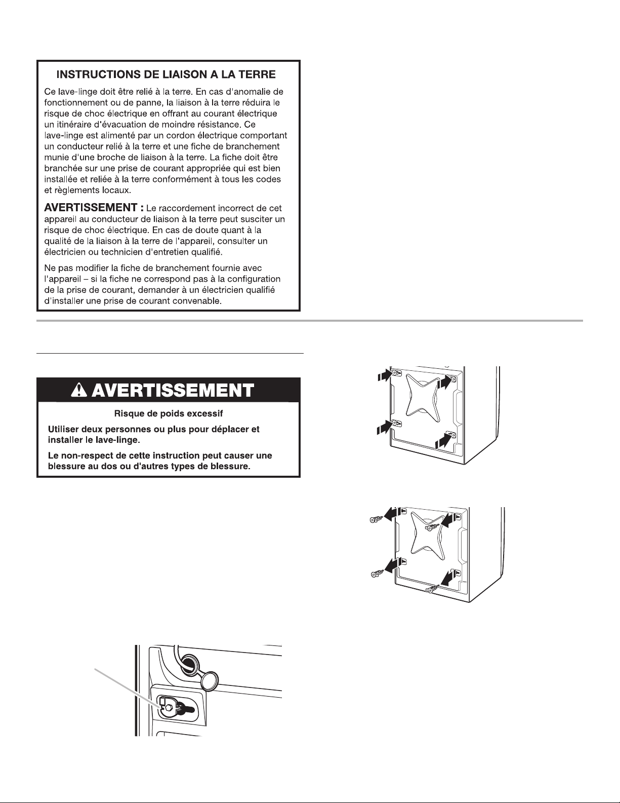
EARTHING INSTRUCTIONS
This washer must be earthed. In the event of a malfunction
or breakdown, earthing will reduce the risk of electric
shock by providing a path of least resistance for electric
current. This washer is equipped with a cord having an
equipment-earthing conductor and an earthing plug. The
plug must be plugged into an appropriate outlet that is
properly installed and earthed in accordance with all local
codes and ordinances.
WARNING: Improper connection of the equipment-
earthing conductor can result in a risk of electric shock.
Check with a qualified electrician or serviceman if you are in
doubt as to whether the appliance is properly earthed.
Do not modify the plug provided with the appliance – if it will
not fit the outlet, have a proper outlet installed by a qualified
electrician.
INSTALLATION INSTRUCTIONS
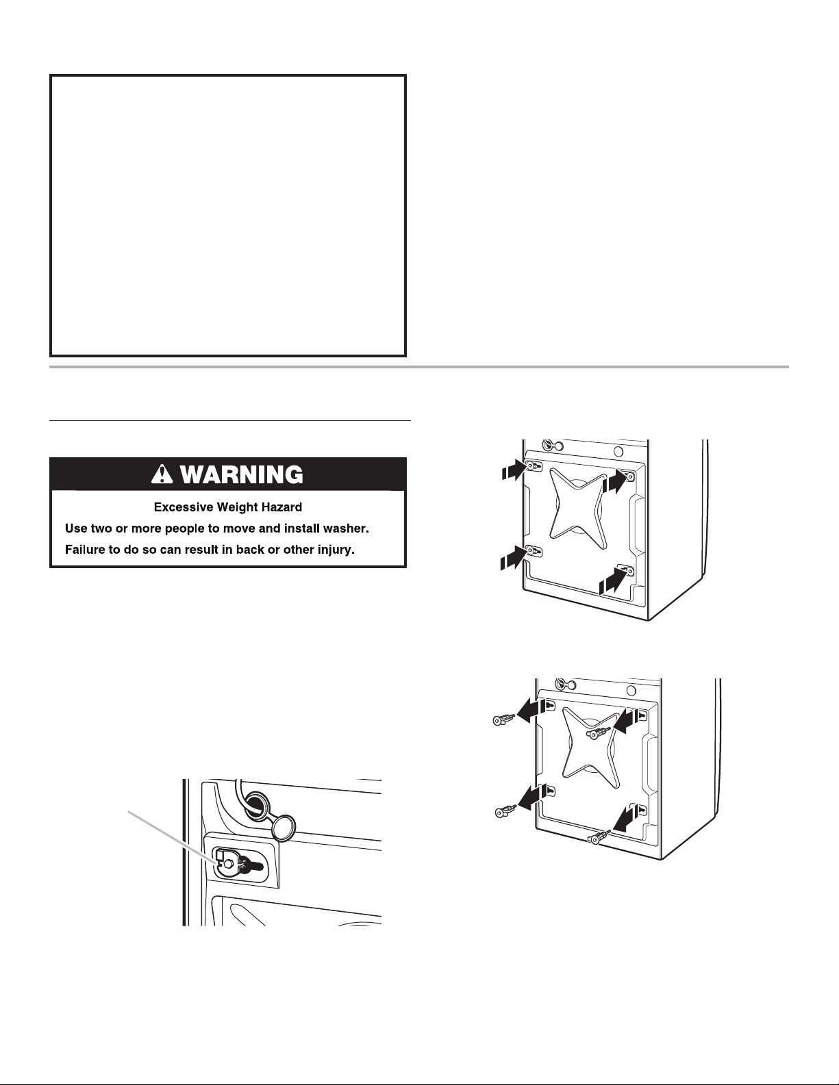
Remove Transport System
NOTE: Electrical safety standards: The manufacturer has
chosen compliance with IEC/EN.60335 standards as the most
appropriate for this product.
■ Sound Pressure Level, Lpa: 58 dbA (uncertainty,
Kpa: +/-3.6 dbA).
2. Using a 1/2" wrench, loosen each of the bolts.
Max. packed weight:
111 kg (244.71 lb)
Max. unpacked weight:
107 kg (235.89 lb)
IMPORTANT: Position the washer so that the rear of the washer
is within approximately 900 mm (3 ft.) of its nal location.
There are 4 shipping bolts in the rear panel of the washer that
support the suspension system during transportation. These
bolts also retain the power cord inside the washer until the bolts
are removed.
1. Keep the washer in the upright position while removing the
shipping bolts.
Shipping bolt
Shipping bolt with plastic spacer
3. Once the bolt is loose, move it to the center of the hole and
completely pull out the bolt, including the plastic spacer
covering the bolt.
4. Once all 4 bolts are removed, discard the bolts and spacers.
Then push the power cord plug into the opening on the right
side of the rear panel and pull the power cord through the
opening on the left side of the rear panel and close holes with
the attached cap. Do not pull plug end of power cord through
the right side hole.
5. Close the bolt holes with the 4 transport bolt hole plugs.
NOTE: If the washer is to be transported at a later date, call your
product distributor or installer. To avoid suspension and structural
damage, your washer must be properly set up for relocation by a
trained professional.
7
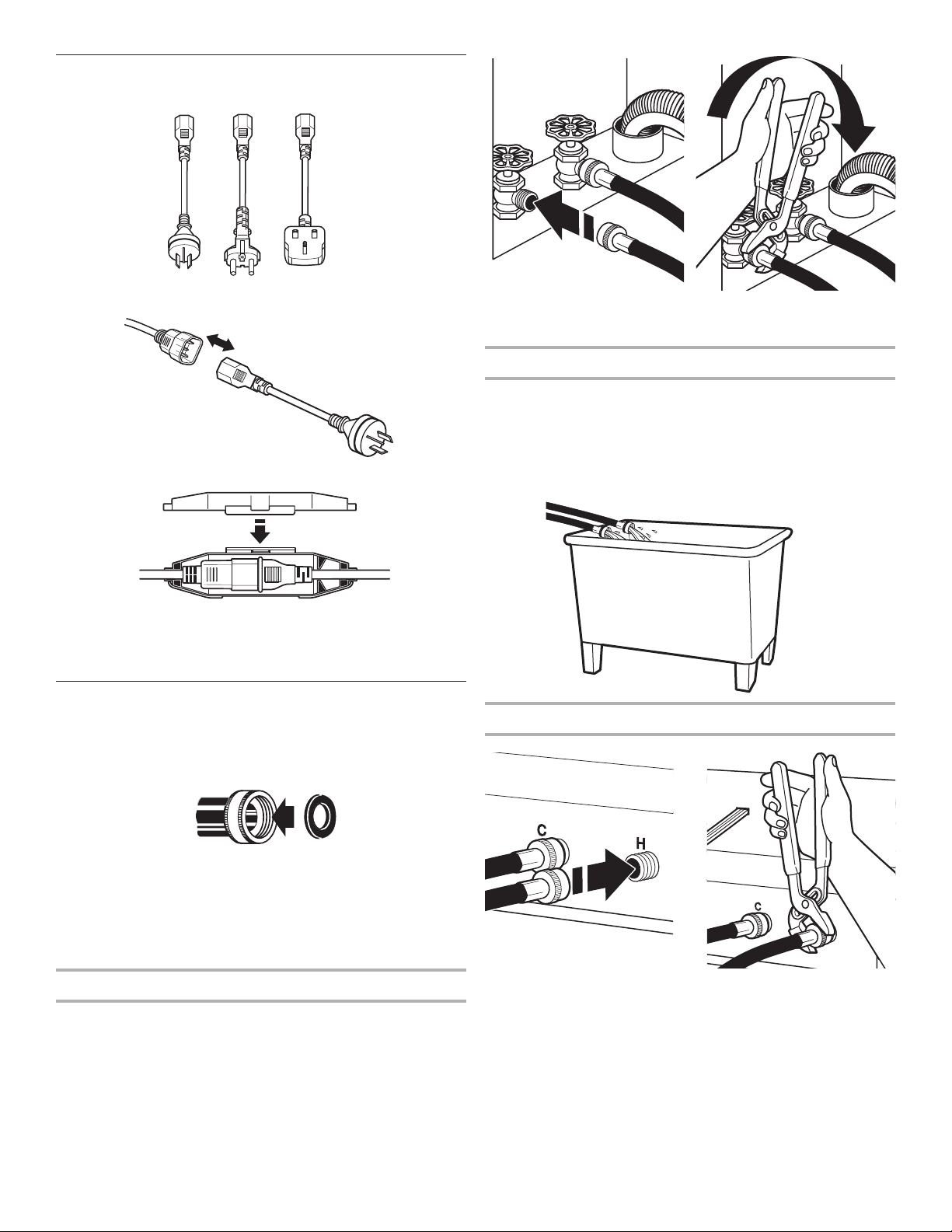
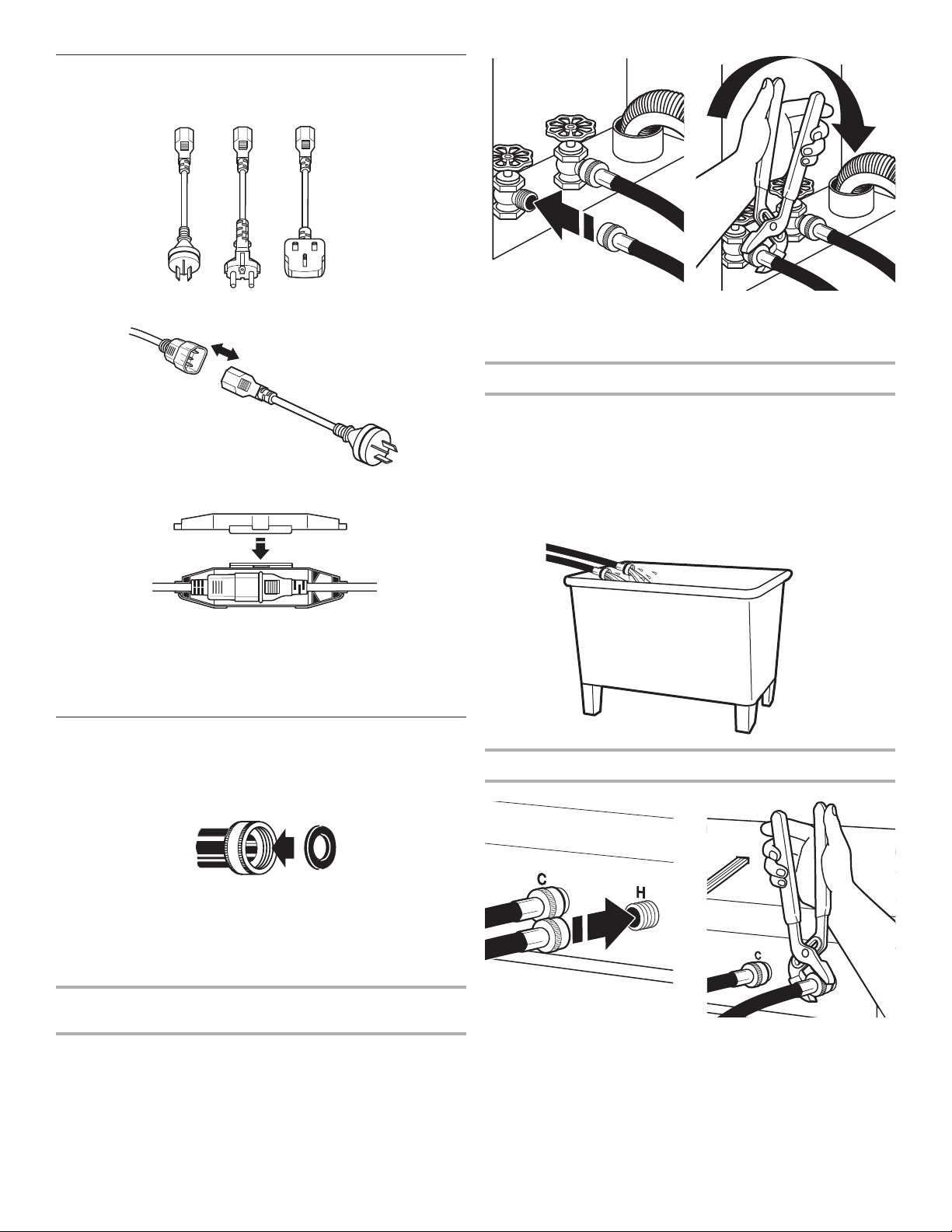
Power Cord Installation
1. Select the plug that ts with the electric receptacle.
2. Assemble the plug into the end of the power cord.
3. Secure the power cord by seating the connection on the cord
lock.
4. Place the cord lock cover and push until it snaps.
5. Make sure the power cord connection is seated on the cord
lock and that the cord lock clamps correctly.
Connect the Inlet Hoses
Connection to the water supply should be in accordance with
local or national regulations. Insert new at washers (supplied)
into each end of the inlet hoses. Firmly seat the washers in the
couplings.
NOTE: Do not overtighten or use tape or sealants on the valve.
Damage to the valves can result.
Clear water lines
■ Run water through both faucets and inlet hoses, into a laundry
tub, drainpipe, or bucket to get rid of particles in the water
lines that might clog the inlet valve screens.
■ Check the temperature of the water to make sure that the hot
water hose is connected to the hot water faucet and that the
cold water hose is connected to the cold water faucet.
Connect inlet hoses to washer
A B
A. Coupling
B. Washer
■ Use the new inlet hoses supplied with washer. Do not re-use
old inlet hoses.
Connect the inlet hoses to the water faucets
Make sure the washer drum is empty.
1. Attach a hose to the hot water tap. Screw on coupling
by hand until it is seated on the washer.
2. Attach a hose to the cold water tap. Screw on coupling
by hand until it is seated on the washer.
3. Using pliers, tighten the couplings with an additional
two-thirds turn.
8
C. Cold water inlet
H. Hot water inlet
1. Attach the hot water hose to the check valve on washer’s
hot (H) water inlet valve. Screw on coupling by hand until
it is seated on the check valve.
2. Attach the cold water hose to the check valve on washer’s
cold (C) water inlet valve. Screw on coupling by hand until it
is seated on the check valve.
3. Using pliers, tighten the couplings with an additional
two-thirds turn.
NOTE: Do not overtighten. Damage to the coupling can result.
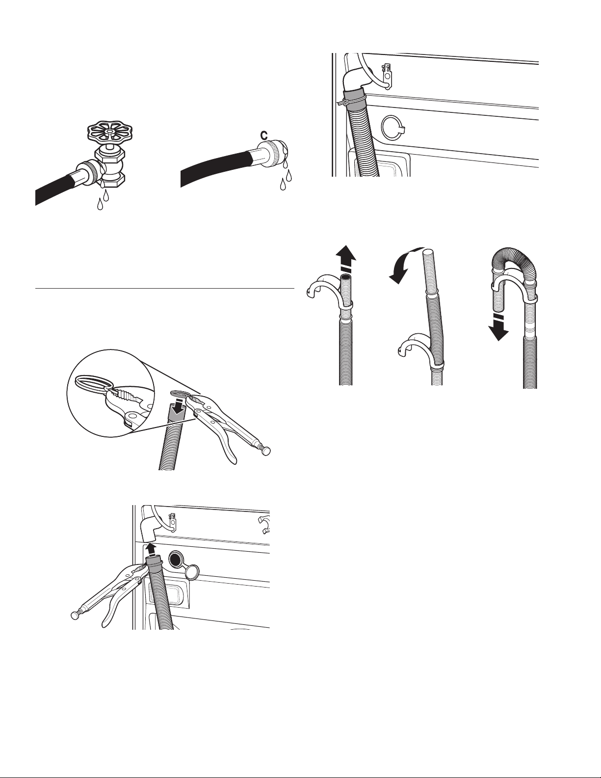
4. Turn on the water taps completely and check for leaks.
NOTE: Replace inlet hoses after 5 years of use to reduce the risk
of hose failure. Record hose installation or replacement dates on
the hoses for future reference.
Periodically inspect and replace hoses if bulges, kinks, cuts,
wear, or leaks are found.
Connect the Drain Hose
Remove drain hose from washer drum
1. Use locking pliers, squeeze hose clamp tabs together and
insert over the end of drain hose.
3. Once drain hose is in place, release pliers.
Washer drain system can be installed using a oor drain, wall
standpipe, oor standpipe, or laundry tub.
Laundry tub drain or standpipe drain
Connect the drain hose form to the corrugated drain hose.
2. Slide drain hose onto washer connection.
To keep drain water from going back into the washer:
■ Use the drain hose form, and do not force excess drain hose
into standpipe. Hose should be secure, but loose enough to
provide a gap for air.
■ Do not lay excess hose on the bottom of the laundry tub.
Floor drain
You may need additional parts. See Floor drain under “Tools and
Parts.”
9
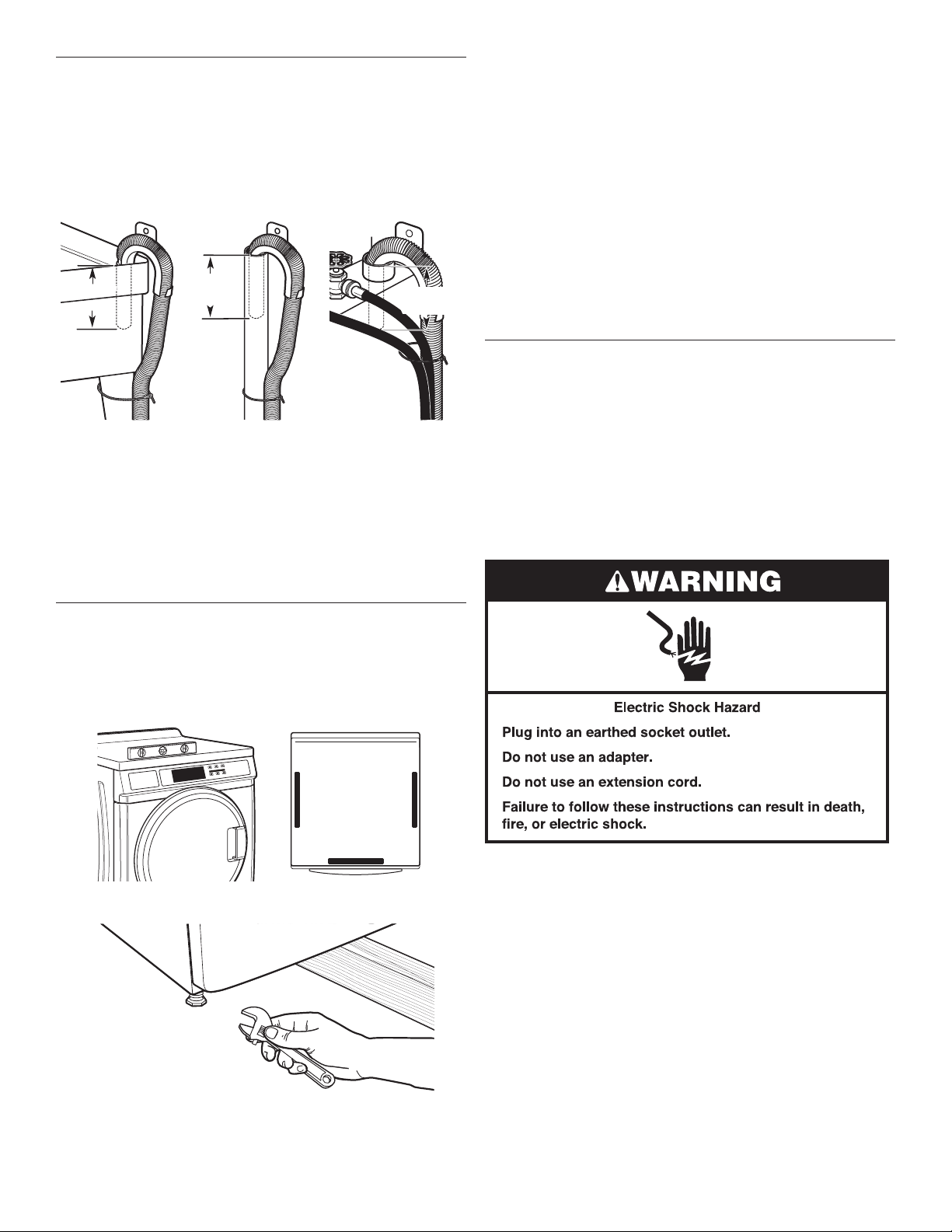
Secure the Drain Hose
Drain hose must be secured to stop the hose from moving when
water is pumped out. If the drain hose moves, water may end up
on the oor.
1. Drape the power cord over the washer top.
2. Move the washer to its nal location.
3. Place the drain hose in the laundry tub or standpipe as shown.
See illustrations A and B.
114 mm"
(4.5")
A B C
NOTES:
■ Do not force excess drain hose back into the rear of the
washer.
■ To avoid siphoning, do not seal or put more than 114 mm
(4.5") of the drain hose into drainpipe or standpipe.
■ If the washer faucets and the drain standpipe are recessed,
put the hooked end of the drain hose in the standpipe as
shown. See illustration C.
114 mm
(4.5")
4.5"
114 mm
(113 mm)
(4.5")
If the washer is against a wall, move the washer out slightly
before tipping back. If the washer is not level, rst prop the
front with a wood block and adjust the feet as necessary; then
prop the back and adjust feet as necessary. Repeat this step
until washer is level.
2. Make sure all four feet are stable and resting on the oor.
Then check that the washer is level (use a level).
3. After the washer is level, use a 9/16" open-end wrench to turn
the nuts on the feet tightly against the washer cabinet.
IMPORTANT: All four feet must be tightened. If the nuts are not
tight against the washer cabinet, the washer may vibrate.
4. The washer should not move front to back, side to side,
or diagonally when pushed on its top edges.
5. Slide the washer to its nal location.
6. Conrm the levelness of the washer.
Complete Installation
1. Check the electrical requirements. Be sure that you have
the correct electrical supply and the recommended earthing
method. See “Electrical Requirements.”
2. Check that all parts are now installed. If there is an extra part,
go back through the steps to see which step was skipped.
3. Check that you have all of your tools.
4. Dispose of/recycle all packaging materials.
5. Check that the water taps are on.
6. Check for leaks around taps and inlet hoses.
Level the Washer
Properly leveling your washer avoids excessive noise and
vibration.
1. Check the levelness of the washer by placing a level on the top
edge of the washer, rst side to side, then front to back.
7. Plug into an earthed socket outlet.
8. To test and to clean your washer, measure 1/2 the detergent
manufacturer’s recommended amount for a medium-size load.
Pour the detergent into the detergent dispenser. Select any
cycle and allow the washer to complete one whole cycle.
10

CONTROL SET-UP INSTRUCTIONS
1. Door must be closed before cycle selection is made.
2. Press fabric setting key pad for the wash cycle desired. After
the cycle is started, the time will display and count down.
General Information
Scrolling ‘out of order’ showing in display, followed by a
failure code
This condition indicates the washer is inoperative.
“0 Minutes” showing in display
This condition indicates the washer cannot be operated. If a door
switch fails, it must be replaced before normal operation can be
restored.
Cold Start (initial rst use)
Washer is programmed at the factory as follows:
■ 11-minute wash period
■ 3 rinses (extra rinse not enabled)
Warm Start (after power failure)
A few seconds after power is restored, if a cycle was in progress
at the time of the power failure, “RESELECT CYCLE” will ash in
the display, indicating the need for a key press to restart washer.
Control Set-up Procedures
IMPORTANT: Read all instructions before operating.
Set-up procedures can be entered by using the Service Access
Code (see “Service Access Code” section).
The washer is now in the set-up mode. The lower fabric setting
key pads and the digital display are used to set up the controls.
The display can contain 4 numbers and/or letters and a decimal
point. These are used to indicate the set-up codes and related
code values available for use in programming the washer.
How to use the key pads to program controls
1. The PERM PRESS key pad is used to adjust the values
associated with set-up codes. Pressing this key pad will
change the value by increments. Rapid adjustment is possible
by holding the key pad down.
2. The DELICATES/KNITS key pad advances you through the
set-up codes. Pressing this key pad will advance you to the
next available set-up code. Holding the key pad down will
automatically advance through the set-up codes at a rate
of 1 per second.
3. The QUICK CYCLE key pad is used to select or deselect
options.
Start Operating Set-up
Before proceeding, it is worth noting that, despite all of the
options available, an owner can simply choose to un-crate a new
semi-pro washer, hook it up, plug it in, and have a washer that
operates. Washers are preset at the factory for a 11-minute wash
period and 3 rinses (no extra rinse).
11

Set-up Codes
■ The DELICATES/KNITS key pad will advance you from code
to code.
■ The PERM PRESS key pad will change the code value.
■ The QUICK CYCLE key pad will select or deselect options.
The set-up code is indicated by the one or two left-hand
characters. The set-up code value is indicated by the two
or three right-hand characters.
CODE EXPLANATION
711 WASH LENGTH
711 This is the number of minutes for WASH. Washer
comes from the factory preset with 11 minutes.
Choose from 9–17 minutes by pressing the
PERM PRESS key pad.
• Press the DELICATES/KNITS key pad once to
advance to next code.
NOTE: This option does not apply to the Quick
Cycle.
8 00
8 00
8 Ar
9 00 CYCLE COUNTER OPTION
9 00
9 0C
ADDITIONAL RINSE OPTION
This option is either SELECTED “ON” or NOT
SELECTED “OFF.”
Not Selected “OFF.”
Selected “ON.” Cannot be combined with the
Super Cycle rinse option.
Press the QUICK CYCLE key pad once for this
selection.
• Press the DELICATES/KNITS key pad once to
advance to next code.
This option is either SELECTED “ON” or NOT
SELECTED “OFF.”
Not Selected “OFF.”
Selected “ON” and not able to be deselected.
Press the QUICK CYCLE key pad 3 consecutive
times to select “ON.” Once selected “ON” it
cannot be deselected.
• Press the DELICATES/KNITS key pad once to
advance to next code.
CODE EXPLANATION
r. 800 TOP SPIN SPEED RPM
r. 800 This can be selected from the following spin
speeds: 600 rpm, 750 rpm, 800 rpm, 1000
(displays as 999) rpm. Step between speeds
by pressing the PERM PRESS key pad. Factory
pre-set for 800 rpm.
• Press the DELICATES/KNITS key pad once to
advance to next code.
A1. 00 PREWASH LENGTH
A1. 00 This is the number of minutes of PREWASH.
Choose 0 to disable the prewash or select
between 2 and 7 minutes by pressing the PERM
PRESS key pad.
• Press the DELICATES/KNITS key pad once to
advance to next code.
A2. 03 FINAL SPIN LENGTH
A2. 03 This is the number of minutes of nal high-speed
spin. Choose from 3–8 minutes by pressing the
PERM PRESS key pad.
• Press the DELICATES/KNITS key pad once to
advance to next code.
If cycle counter (9 0C) is selected, the following is true:
1 00 Number of cycles 1 02 = 200
in HUNDREDS.
2 00 Number of cycles 2 25 = 25
in ONES.
TOTAL CYCLES = 225 cycles
This is “VIEW ONLY” and cannot be cleared.
• Press the DELICATES/KNITS button once to advance to next
code.
EXIT FROM SET-UP MODE
Remove power, open console, reinsert plug into AA1, close
console, and apply power.
CODE EXPLANATION
5. 00 TIME-OF-DAY CLOCK, MINUTES
5. 00 This is the TIME-OF-DAY CLOCK, minute setting;
select 0–59 minutes by pressing the PERM
PRESS key pad.
• Press the DELICATES/KNITS key pad once to
advance to next code.
6. 00 TIME-OF-DAY CLOCK, HOURS
NOTE: Uses the 24 hr. clock.
6. 00 This is the TIME-OF-DAY CLOCK, hour setting;
select 0–23 hours by pressing the PERM PRESS
key pad.
• Press the DELICATES/KNITS key pad once to
advance to next code.
12
Washer Diagnostic Mode
To enter the “Washer Diagnostic Mode,” rst enter “Start
Operating Set-up.” Then press and hold the QUICK CYCLE key
pad for 1 second while in set-up code 6, anytime a diagnostic
code is present.
On entry to diagnostic mode the entire display will ash, a
cycle in process is canceled, money in escrow is cleared, and
diagnostic codes are cleared. If a diagnostic code persists,
it must be corrected before the following cycle options are
permitted.
There are ve possible ways to initiate cycle activity from
diagnostic mode as follows:
1. Washer Cleanout cycle – With the entire display ashing, this
cycle is started by pressing the BRIGHTS key pad.
Use the Washer Cleanout cycle once a month to keep the
inside of your washer fresh and clean. This cycle uses a higher
water level. Use with liquid chlorine bleach to thoroughly clean
the inside of the washer. This cycle should not be interrupted.
IMPORTANT: Do not place garments or other items in the
washer during the Washer Cleanout cycle. Use this cycle with
an empty wash drum.

2. Manual Overview Test – With the entire display ashing, this
cycle is started by pressing the WHITES key pad. This cycle
provides more typical full length lls, tumbles, drains, and
actuator dispenser movement, allowing for a more thorough
analysis of the washer operation, including pressure switch
behavior.
3. Quick Spin Cycle – With the entire display ashing, this cycle is
started by pressing the COLORS key pad. This cycle provides
a method to quickly drain and spin (remove water from the
washer) if desired.
4. Quick Overview Test – With the entire display ashing, this
cycle is started by pressing the DELICATES/KNITS key pad.
This cycle provides a quick verication that the cold and hot
water valves, dispensers, and pump motor are working, as well
as actuator dispenser movement. It also includes door lock,
drain, and spin operations.
Pressing the QUICK CYCLE key pad will exit diagnostic mode
and cancel a diagnostic cycle in process.
DIAGNOSTIC CODES
If one of the following has occurred, the appropriate diagnostic
code will be in the display.
d9 Low voltage detected for 8 seconds.
F20 Slow Fill. The washer will not detect water input
for 4 min. Pressure switch failure or no water
inlet. This code is reported as d8 on d7.
F22 The door is not able to lock. Door lock error or
someone trying to start the washer, by pressing
the door switch with their nger.
(For any other display consult service personnel.)
SERVICE ACCESS CODE
This code can be entered to access service mode without
removing the console. If the washer is not in failure mode, the
door must be opened to proceed. Service Access Code contains
6 steps and some are timed. Using only the three bottom buttons
(numbered 1, 2, and 3 from left to right):
1. Press 2 for longer than 2 seconds but less than 10 seconds.
2. Press 1 & 3 together for 2 seconds, then release. Displays S 3.
3. Press 1 & 2 together, then release. Displays S 4.
4. Press 2 & 3 together, then release. Displays S 5.
5. Press 2, then release. Display shows “codE”.
6. Wait at least 2 seconds, but not more than 15 seconds, then
press in succession: 3, 2, 1, 3.
NOTE: If the Service Access Code procedure is not completed
properly, as noted above, there is a 15-second delay before it can
be attempted again.
When the Service Access Code is used, there are 3 options
to exit.
1. From Set-up Code 8, press key #1 for 4 seconds.
2. Wait 2 minutes without touching any keypads (without
diagnostic modes running).
3. Power down the washer, then reapply power.
WASHER HELP MODE
This mode is entered by pressing the PERM PRESS key pad
while in Set-up option code 2.XX.
In help mode, other display symbols and elements are mapped
to reect the state of various inputs and outputs as follows:
Display Symbol Description
Wash Water sensed at wash level.
* Low voltage present (below about
90 VAC).
° (Circle above digit) Door closed.
DOOR LOCKED Door sensed locked.
COLD Cold water relay on.
HOT Hot water relay on.
OR Door unlock.
AVAILABLE Drain pump ON.
NOTE: A technical sheet is supplied taped to inside of lower
front panel, which includes fault codes and a machine schematic
diagram.
WASHER CARE
Cleaning Your Washer
Cleaning the Door Seal/Bellow
1. Open the washer door and remove any clothing or items from
the washer.
2. Inspect the colored seal/bellow between the door opening
and the drum for stained areas. Pull back the seal/bellow to
inspect all areas under the seal/bellow and to check for foreign
objects.
A
A. Seal/Bellow
3. If stained areas are found, wipe down these areas of the seal/
bellow, using the procedure that follows:
a) Mix a dilute solution, using 177 mL (3/4 cup) of liquid
chlorine bleach, and 3.8 L (1 gal.) of warm tap water.
b) Wipe the seal/bellow area with the dilute solution, using
a damp cloth.
c) Let stand 5 minutes.
d) Wipe down area thoroughly with a dry cloth and let the
washer interior air dry with door open.
IMPORTANT:
■ Wear rubber gloves when cleaning for prolonged periods.
■ Refer to the bleach manufacturer’s instructions for proper use.
Washer Maintenance Procedure
This washer has a special cycle that uses higher water volumes
in combination with liquid chlorine bleach to thoroughly clean
the inside of the washer.
NOTES:
■ Read these instructions completely before beginning the
cleaning process.
13

■ If necessary, the cleaning cycle may be interrupted by
pressing the QUICK CYCLE button twice. However, this will
not immediately stop the cycle. The washer will continue
with several rinse and drain steps to ensure that all remaining
bleach is rinsed from the washer.
Begin procedure
1. Open the washer door and remove any clothing or items from
the washer.
2. Use liquid chlorine bleach:
Open the dispenser drawer and immediately add 160 mL
(2/3 cup) of liquid chlorine bleach to the bleach compartment.
NOTE: Do not add any detergent to this cycle. Use of more
than 160 mL (2/3 cup) of bleach will cause product damage
over time.
3. Close the washer door and the dispenser drawer.
4. To start the Clean Washer cycle, rst enter “Start Operating
Set-up.” Then press and hold QUICK CYCLE for 1 second.
With the entire display ashing, press BRIGHTS.
NOTE: The drum will rotate, then the door will unlock, lock
again, and then the cycle will continue.
■ The washer will not ll, but the drum will rotate while
the washer runs a short sensing cycle. This will take
approximately 3 minutes.
5. The cycle will determine whether clothing or other items are
in the washer.
a) If no items are detected in the washer, it will proceed
to Step 7.
b) If any items are detected in the washer, “rL” or “F-34” will be
displayed. Then the door will unlock.
■ Press QUICK CYCLE to cancel the failure code.
Then repeat steps 1, 3, and 4 to start the cycle again.
6. Once the cycle has begun, allow the cycle to complete.
7. After the cycle is complete, leave the door open slightly,
to allow for better ventilation and drying of washer interior.
Always do the following to maintain washer freshness:
■ Use only detergent for automatic washer.
■ Leave the door slightly open after each cycle to allow for
better ventilation and drying of washer interior.
■ Clean the washer monthly using the “Washer Maintenance
Procedure,” 160 mL (2/3 cup) of liquid chlorine bleach.
■ If the procedure does not sufciently improve the washer
freshness, please evaluate your installation and usage
conditions for other causes.
Cleaning the exterior
Use a soft damp cloth or sponge to wipe up any spills.
Occasionally wipe the outside of your washer to keep it looking
new. Use mild soap and water. Do not use abrasive products.
Cleaning the dispenser drawer
The dispenser drawer is removable for easy cleaning.
1. Unlock the dispenser drawer by pressing the Release Lever.
Remove the drawer.
2. Remove the inserts (the siphon from the softener and bleach
compartments).
3. Wash the parts under running water.
NOTE: Do not wash components in the dishwasher.
4. Replace the inserts and return the dispenser to the drawer.
Water Inlet Hoses
Replace inlet hoses after 5 years of use to reduce the risk of
hose failure. Periodically inspect and replace inlet hoses if bulges,
kinks, cuts, wear, or leaks are found.
When replacing your inlet hoses, record the date of replacement.
ASSISTANCE OR SERVICE
Before calling for assistance or service, please check
“Troubleshooting.” It may save you the cost of a service call. If
you still need help, contact the dealer from whom you purchased
the appliance, or a Whirlpool designated service company.
When calling, please know the purchase date and the complete
model and serial number of your appliance. This information will
help us to better respond to your request.
Whirlpool Corporation, Benton Harbor, Michigan 49022, USA.
Manufacturer site: Whirlpool Mexico S.A. de C.V., Antigua Carretera a Roma Km 9,
Col. El Milagro, Apodaca, Nuevo León, C.P. 66634, Mexico.
EU representative: Whirlpool UK Ltd, Croydon, CR9 4RY, UK
Bauknecht Hausgeräte Gmbh, D-73614 Schorndorf
Accessories
Enhance your washer with these premium accessories. For more
high-quality items or to order, contact your authorized Whirlpool
distributor.
Part
Number
8212526 Washer drip tray, ts under all
31682 All-purpose appliance cleaner
1903WH Laundry supply storage cart
Accessory
14

EU - DECLARATION OF CONFORMITY
GPO, Schorndorf
Name and signature of aurthorised person
CE - DECLARATION DE CONFORMITE
WE (nous): BAUKNECHT HAUSGERÄTE GmbH, D-73614 Schorndorf
representing (représentant): WHIRLPOOL EUROPE S.r.l I-21025 COMERIO
declare under our sole responsibility that the product
déclarons sous notre propre responsabilité que le produit
washing machines Whirlpool 3LCHW9100YQ
(machine à laver le linge):
Maytag MHN30PN
Maytag MHN30PD
to which this declaration relates is in conformity with the following standard(s) or other
normative document(s)
auquel se référe cette déclaration est conforme aux normes suivantes ou autres documents normatifs
EN 60335-1:2002+A1+A2+A11+A12+A13+A14+A15
EN 60335-2-7:2010
EN 62233:2008
EN 61770:1999+A1:2004+A2:2006
EN ISO 10472-1:2008
EN ISO 10472-2:2008
EN ISO 12100-1:2010
EN 55014-1:2006+A1:2009
EN 55014-2:1997+A1:2001+A2:2008
EN 61000-3-2:2006+A1:2009+A2:2009
EN 61000-3-3:2008
following the provisions of Directive(s
suivant les prévisions des Directives:
):
2006/42/EC MACHINERY DIRECTIVE
2004/108/EC ELECTROMAGNETIC COMPATIBILITY DIRECTIVE
2011/65/EU ROHS DIRECTIVE
2002/96/EC WEEE DIRECTIVE
represented by
Schorndorf, 01.06.2012 Micael Zirondi Karl-Dieter Klingenstein
Place and date:
lieu et date
Director PDC FC EMEA Product Approval
Nom et signature de la personne autorisée
15
SECURITE DU LAVE-LINGE
16
MISE AU REBUT DU LAVE-LINGE
AB
Nomenclature du modèle
3L – Code prise secteur tension 230 V/50 Hz
CHW – Lave-linge commercial horizontal
91 – Numéro du type de modèle
EXIGENCES D’INSTALLATION
Outillage et pièces
Rassembler les outils et pièces nécessaires avant de commencer
l’installation. Les pièces fournies se trouvent dans le tambour du
lave-linge.
Outils nécessaires au raccordement des tuyaux d’arrivée
d’eau :
■ Pince (ouverture jusqu’à 39,5 mm [1
■ Lampe de poche (facultative)
Outils nécessaires à l’installation
■ Clés plates de 1/2" et 9/16"
■ Tournevis de sécurité Torx
■ Tourne-écrou de 1/4"
■ Niveau
■ Cale en bois
■ Règle ou mètre ruban
®†
T-20
Pièces fournies
9
⁄16"])
C
F
Autres pièces
Il se peut que l’installation nécessite des pièces supplémentaires.
Pour acheter l’un des articles indiqués ici, contacter votre
concessionnaire Whirlpool agréé.
Si vous avez Vous devrez acheter
Evier de
buanderie ou
Système de pompe de puisard (si non déjà
disponible)
tuyau rigide de
rejet à l’égout
plus haut que
2,4 m (96")
Egout surélevé Evier de vidange standard de 76 L (20 gal.)
de 762 mm (30") de hauteur ou évier utilitaire
et pompe de puisard (disponibles chez votre
fournisseur local d'articles de plomberie)
Egout au
plancher
Brise-siphon, pièce n° 285320; tuyau de
vidange additionnel, pièce n° 8318155;
et ensemble de système de vidange au
plancher, pièce n° 280129
Tuyau de
vidange trop
Trousse de rallonge du tuyau de vidange
de 1,2 m (4 pi), pièce n° 285834
court
DE
A. Bride de retenue pour D. Bouchons d’obturation des
tuyau de vidange (en forme de U) boulons de transport (4)
B. Tuyaux d’arrivée d’eau (2) E. Courroie perlée
C. Rondelles pour tuyau F. Tuyau de vidange
d’arrivée d'eau (4) G. Bride de tuyau
†® TORX est une marque déposée de Saturn Fasteners, Inc.
G
17
Options
686 mm
Piédestal
Vous avez la possibilité d’acheter des piédestaux séparément
pour ce lave-linge. Le piédestal augmentera la taille totale du
lave-linge.
Piédestal facultatif
Dégagements de séparation à respecter
■ L’emplacement doit être assez grand pour permettre d’ouvrir
complètement la porte du lave-linge.
■ Prévoir davantage d’espace pour faciliter l’installation
et l’entretien. La porte s’ouvre à plus de 90° et n’est pas
réversible.
■ Un espace supplémentaire peut être requis pour les moulures
de porte et de plancher et pour les plinthes.
■ Un espace supplémentaire de 25 mm (1") de tous les côtés
du lave-linge est recommandé pour réduire le transfert
du bruit.
■ Il faut aussi prendre en compte l’espace requis entre
les appareils voisins.
■ Le débranchement de la prise d’alimentation secteur fait
ofce de commande d’arrêt d’urgence. Lorsqu’elle est
branchée, la prise d’alimentation secteur doit être visible
et accessible à l’utilisateur an que la déconnexion entre
le lave-linge et l’alimentation secteur soit possible.
Hauteur du
piédestal
Hauteur
approximative
Couleur Pièce
numéro
avec lave-linge
(73 mm) 27/8" (1207 mm) 47,5" Blanc WHP0400VW
Exigences d’emplacement
Le choix d’un emplacement approprié pour le lave-linge
en améliore le rendement et réduit au minimum le bruit
et le “déplacement” possible du lave-linge.
Le lave-linge peut être installé sous un comptoir personnalisé,
ou dans un sous-sol, une salle de buanderie ou un encastrement.
Voir “Système de vidange”.
Il faut aussi prendre en compte les exigences d’emplacement
des appareils voisins. C’est à l’utilisateur qu’incombe
la responsabilité de réaliser une installation correcte.
Il vous faudra
■ Un chauffe-eau conguré pour fournir de l’eau à 60°C (140°F)
au lave-linge.
■ Une prise électrique reliée à la terre située à 1,8 m (6 pi)
maximum du cordon d’alimentation électrique xé à l’arrière
du lave-linge. Voir “Spécications électriques”.
■ Des robinets d’eau chaude et d’eau froide situés à 1,2 m
(4 pi) maximum des robinets d’admission d’eau chaude
et d’eau froide et une pression d’eau de 137,9–689,6 kPa
(20–100 lb/po²).
■ Un plancher de niveau ayant une pente maximale de 25 mm
(1") sous l’ensemble du lave-linge. L’installation du lave-linge
sur des surfaces de sol souples, telles que tapis ou surfaces
avec sous-couche en mousse n’est pas recommandée.
■ Un plancher robuste et solide capable de soutenir le poids
total du lave-linge (eau et charge) de 180 kg (400 lb).
Ne pas faire fonctionner le lave-linge à des températures
inférieures à 0ºC (32ºF). Une certaine quantité d’eau peut
demeurer dans le lave-linge et causer des dommages
à des températures basses.
Dimensions du lave-linge
1282 mm
1
(50
/2")
La porte n’est pas réversible.
(27")
732 mm
13
/16")
(28
961 mm
5
(37
/6")
Un système de vidange au plancher doit être installé sous la
cloison. Des cloisons pré-fabriquées avec prises de courant,
canalisations d’arrivée d’eau et aménagements pour installation
de vidangeage ne doivent être installées que là où les codes
locaux l’autorisent.
18
Système de vidange
Le lave-linge peut être installé en utilisant le système de rejet à
l’égout (au plancher ou mural), le système de vidange de l’évier
de buanderie ou le système de vidange au plancher. Sélectionner
la méthode d’installation du tuyau de vidange selon les besoins.
Voir “Outillage et pièces”.
Système de rejet à l’égout – mural ou au plancher
(vues A et B)
Le système de rejet à l’égout nécessite un tuyau rigide
d’un diamètre minimum de 50 mm (2"). La capacité minimale
d’acheminement ne doit pas être inférieure à 45,5 L (12 gal.)
par minute.
Le sommet du tuyau rigide de rejet à l’égout doit être au moins
à 762 mm (30") de hauteur et au maximum à 2,4 m (96" )
de la base du lave-linge.
762 mm
(30" min.)
Spécications électriques
A B
Système de vidange avec évier de buanderie (vue C)
L’évier de buanderie doit avoir une capacité minimale de 76 L
(20 gal.). La partie supérieure de l’évier de buanderie doit être
à au moins 762 mm (30") au-dessus du plancher.
Système de vidange au plancher (vue D)
Le système de vidange au plancher nécessite un brise-siphon qui
peut être acheté séparément. Voir “Outillage et pièces”.
Le brise-siphon doit être au moins à 710 mm (28") de la base
du lave-linge. Des tuyaux supplémentaires peuvent être requis.
762 mm
(30" min.)
C D
710 mm
(28" min.)
■ Une alimentation électrique de 220–240V, 50 Hz, protégée
par un fusible est requise. On recommande d’utiliser un
fusible temporisé de 10 à 16 A ou un disjoncteur temporisé.
■ Ce lave-linge comporte un cordon d’alimentation électrique
pour liaison à la terre.
■ Pour minimiser les risques de choc électrique, on doit
brancher le cordon sur une prise de courant de conguration
correspondante reliée à la terre et installée conformément
aux codes et règlements locaux. Si une prise de courant de
conguration correspondante n’est pas disponible, le client
a la responsabilité et l’obligation de faire installer par un
électricien qualié une prise de courant correctement reliée
à la terre.
■ Si les codes le permettent et si on utilise un conducteur
distinct de liaison à la terre, il est recommandé qu’un
électricien qualié vérie la qualité de la liaison à la terre.
■ Si le cordon d’alimentation est endommagé, il doit être
remplacé par le fabricant, son agent de service ou toute
autre personne qualiée an d’éviter tout danger.
■ Ne pas utiliser une tuyauterie de gaz pour le raccordement
à la terre.
■ En cas de doute quant à la qualité de la liaison à la terre
du lave-linge, consulter un électricien qualié.
19
■ Ne pas installer un fusible dans le conducteur neutre ou
le conducteur de liaison à la terre.
REMARQUE : Normes de sécurité électriques : Pour ce produit,
le fabricant a estimé que la mise en conformité aux normes
IEC/EN.60335 était la plus appropriée.
■ Niveau d’émission sonore, Lpa : 58 dbA (uncertainty,
Kpa: +/-3.6 dbA)
INSTRUCTIONS D’INSTALLATION
Dépose du système de transport
Poids max. avec emballage :
111 kg (244,71 lb)
Poids max. sans emballage :
107 kg (235,89 lb)
IMPORTANT : Positionner le lave-linge de sorte que l’arrière du
lave-linge soit à environ 900 mm (3 pi) de son emplacement nal.
On trouve sur le panneau arrière du lave-linge 4 boulons
d’expédition qui soutiennent le système de suspension
durant le transport. Ces boulons retiennent aussi le cordon
d’alimentation électrique à l’intérieur du lave-linge jusqu’à
ce que les boulons soient retirés.
1. Laisser le lave-linge en position verticale pendant que l’on ôte
les boulons d’expédition.
Boulon d’expédition
Shipping bolt
Boulon d’expédition avec cale d’espacement en plastique
20
2. Au moyen d’une clé de 1/2", desserrer chacun des boulons.
3. Une fois le boulon desserré, le déplacer au centre du
trou et retirer complètement le boulon, y compris la cale
d’espacement en plastique couvrant le boulon.
4. Une fois que les 4 boulons ont été retirés, jeter les boulons
et les cales d’espacement. Puis pousser la che du cordon
d’alimentation électrique à travers l’ouverture sur le côté droit
du panneau arrière, tirer le cordon d’alimentation électrique
à travers l’ouverture sur le côté gauche du panneau arrière
et obturer les trous avec le bouchon fourni. Ne pas tirer
l’extrémité du cordon d’alimentation à travers le trou de droit.
5. Obturer les trous des boulons avec les 4 bouchons pour
les trous des boulons de transport.
REMARQUE : Si le lave-linge doit être transporté à une date
ultérieure, appeler le distributeur ou l'installateur du produit. Pour
éviter des dommages concernant la suspension et la structure,
votre lave-linge doit être correctement monté pour réinstallation
ultérieure par un technicien certié.
Installation du cordon d’alimentation
1. Sélectionner la prise qui correspond à la prise électrique
murale.
2. Fixer la prise à l’extrémité du cordon d’alimentation.
REMARQUE : Ne pas serrer excessivement ou utiliser du ruban
adhésif ou un calfeutrant sur le robinet. Les tuyaux d’arrivée
d’eau risquent d’être endommagés.
Purger les canalisations d’eau
■ Laisser s’écouler l’eau des deux robinets et des tuyaux
3. Fixer le cordon d’alimentation en immobilisant le raccord
sur le dispositif de blocage du cordon.
4. Installer le couvercle du dispositif de blocage du cordon
et appuyer jusqu’à ce qu’il s’emboîte.
5. S’assurer que le raccord du cordon d’alimentation est
immobilisé sur le dispositif de blocage du cordon et que
le serrage du dispositif de blocage est correct.
■ Vérier la température de l’eau pour s’assurer que le tuyau
Raccordement des tuyaux d’arrivée d’eau
Le raccordement à l’alimentation en eau doit être conforme
aux règlements locaux et nationaux. Insérer les rondelles plates
neuves (fournies) dans chaque extrémité des tuyaux d’arrivée
d’eau. Insérer fermement les rondelles dans les raccords.
Connecter les tuyaux d’arrivée d’eau au lave-linge
d’arrivée d’eau dans un évier de buanderie, un tuyau rigide
de rejet à l’égout ou un seau, pour éliminer les particules se
trouvant dans les canalisations d’eau qui pourraient obstruer
les tamis de la valve d’arrivée d’eau.
d’eau chaude est connecté au robinet d’eau chaude et que
le tuyau d’eau froide est connecté au robinet d’eau froide.
A B
A. Raccord
B. Rondelle
■ Utiliser les nouveaux tuyaux d’arrivée d’eau fournis avec le
lave-linge. Ne pas réutiliser de tuyaux d’arrivée d’eau usagés.
Connecter les tuyaux d’arrivée d’eau aux robinets
d’eau
S’assurer que le tambour du lave-linge est vide.
1. Fixer un tuyau au robinet d’eau chaude. Visser complètement
le raccord à la main pour qu’il comprime le joint.
2. Fixer un tuyau au robinet d’eau froide. Visser complètement
le raccord à la main pour qu’il comprime le joint.
3. A l’aide d’une pince, serrer les raccords en effectuant deux
tiers de tour supplémentaires.
C. Tuyau d’arrivée d’eau froide
H. Tuyau d’arrivée d’eau chaude
1. Fixer le tuyau d’eau chaude à la valve du tuyau d’arrivée d’eau
chaude (H) du lave-linge. Visser complètement le raccord
à la main pour qu’il comprime le joint.
21
 Loading...