

Whirlpool 3LCHW9100WQ Installation Instructions
®
A
INSTALLATION INSTRUCTIONS
SEMI-PRO FRONT-LOAD WASHER
INSTRUCTIONS D’INSTALLATION
LAVE-LINGE SEMI-PRO A CHARGEMENT FRONTAL
INSTRUCCIONES DE INSTALACIÓN
LAVADORA SEMIPROFESIONAL DE CARGA FRONTAL
ISTRUZIONI D’INSTALLAZIONE
LAVATRICE SEMI-PRO A CARICAMENTO FRONTALE
Table of Contents/Table des matières/Índice/Sommario....................................................2
Model/Modèle/Modelo/Modello
3LCHW9100WQ
W10299462

TABLE OF CONTENTS
ÍNDICE
WASHER SAFETY ..........................................................................3
WASHER DISPOSAL......................................................................4
INSTALLATION REQUIREMENTS ................................................4
Tools and Parts ............................................................................ 4
Options.........................................................................................5
Location Requirements................................................................5
Drain System................................................................................6
Electrical Requirements ............................................................... 6
INSTALLATION INSTRUCTIONS ..................................................7
Remove Transport System ..........................................................7
Power Cord Installation................................................................7
Connect the Inlet Hoses...............................................................7
Route the Drain Hose...................................................................8
Secure the Drain Hose.................................................................9
Level the Washer..........................................................................9
Complete Installation ...................................................................9
CONTROL SET-UP INSTRUCTIONS..........................................10
General Information....................................................................10
Control Set-up Procedures........................................................10
Set-up Codes.............................................................................10
Washer Diagnostic Mode...........................................................11
WASHER CARE ............................................................................12
Cleaning Your Washer ...............................................................12
Water Inlet Hoses.......................................................................13
ASSISTANCE OR SERVICE.........................................................13
SEGURIDAD DE LA LAVADORA.................................................26
ELIMINACIÓN DE LA LAVADORA..............................................27
REQUISITOS DE INSTALACIÓN.................................................27
Herramientas y piezas................................................................27
Opciones ....................................................................................28
Requisitos de ubicación.............................................................28
Sistema de desagüe...................................................................29
Requisitos eléctricos ..................................................................29
INSTRUCCIONES DE INSTALACIÓN.........................................30
Eliminación del sistema protector de transporte.......................30
Instalación del cable de suministro de energía .........................31
Conexión de las mangueras de entrada....................................31
Tendido de la manguera de desagüe ........................................32
Fijación de la manguera de desagüe.........................................32
Nivelación de la lavadora ...........................................................32
Complete la instalación..............................................................33
INSTRUCCIONES DE PROGRAMACIÓN DEL CONTROL .......33
Información general....................................................................33
Procedimientos de programación del control ...........................33
Códigos de programación .........................................................34
Modo de diagnóstico de la lavadora .........................................35
CUIDADO DE LA LAVADORA .....................................................36
Cómo limpiar su lavadora ..........................................................36
Mangueras de entrada de agua.................................................37
AYUDA O SERVICIO TÉCNICO...................................................37
TABLE DES MATIERES
SECURITE DU LAVE-LINGE........................................................14
MISE AU REBUT DU LAVE-LINGE .............................................15
EXIGENCES D’INSTALLATION...................................................15
Outillage et pièces......................................................................15
Options.......................................................................................16
Exigences d’emplacement.........................................................16
Système de vidange...................................................................17
Spécifications électriques..........................................................17
INSTRUCTIONS D’INSTALLATION ............................................18
Dépose du système de transport ..............................................18
Installation du cordon d’alimentation ........................................18
Raccordement des tuyaux d’arrivée d’eau................................19
Acheminement du tuyau de vidange.........................................20
Immobilisation du tuyau de vidange..........................................20
Réglage de l’aplomb du lave-linge ............................................20
Achever l’installation ..................................................................21
INSTRUCTIONS DE PARAMÉTRAGE DU MODULE
DE COMMANDE...........................................................................21
Informations générales...............................................................21
Procédures de réglage des systèmes de commande...............21
Codes de paramétrage ..............................................................22
Mode de diagnostic du lave-linge .............................................23
ENTRETIEN DU LAVE-LINGE .....................................................24
Nettoyage du lave-linge .............................................................24
Tuyaux d’arrivée d’eau...............................................................25
ASSISTANCE OU SERVICE.........................................................25
SOMMARIO
SICUREZZA DELLA LAVATRICE................................................38
SMALTIMENTO DELLA LAVATRICE..........................................39
REQUISITI D’INSTALLAZIONE ...................................................39
Attrezzi e componenti ................................................................39
Opzioni........................................................................................40
Requisiti di posizionamento.......................................................40
Sistema di scarico......................................................................41
Requisiti elettrici .........................................................................41
ISTRUZIONI D’INSTALLAZIONE.................................................42
Rimozione del sistema di trasporto ...........................................42
Installazione del cavo di alimentazione......................................42
Collegamento dei tubi ................................................................42
Instradamento del tubo di scarico .............................................43
Fissaggio del tubo di scarico .....................................................44
Livellamento della lavatrice ........................................................44
Installazione completa................................................................44
ISTRUZIONI PER L’UTENTE E DI CONFIGURAZIONE ............45
Informazioni di carattere generale..............................................45
Procedure di configurazione dei comandi.................................45
Codici di configurazione.............................................................45
Modalità diagnostica della lavatrice...........................................46
MANUTENZIONE DELLA LAVATRICE .......................................47
Pulizia della lavatrice ..................................................................47
Tubi di ingresso dell’acqua ........................................................48
ASSISTENZA O MANUTENZIONE..............................................48
2
WASHER SAFETY
Your safety and the safety of others are very important.
We have provided many important safety messages in this manual and on your appliance. Always read and obey all safety
messages.
This is the safety alert symbol.
This symbol alerts you to potential hazards that can kill or hurt you and others.
All safety messages will follow the safety alert symbol and either the word “DANGER” or “WARNING.”
These words mean:
You can be killed or seriously injured if you don't immediately
DANGER
WARNING
All safety messages will tell you what the potential hazard is, tell you how to reduce the chance of injury, and tell you what can
happen if the instructions are not followed.
follow instructions.
can be killed or seriously injured if you don't
You
instructions.
follow
3
WASHER DISPOSAL
INSTALLATION REQUIREMENTS
Tools and Parts
Gather the required tools and parts before starting installation.
The parts supplied are in the washer drum.
Tools needed for connecting the water inlet hoses
■ Pliers (that open to
39.5 mm [1
9
/16"])
Tools needed for installation
■ Open end wrenches
1/2" and 9/16"
■ To rx
■ 1/4" nut driver
Parts supplied
®†
T-20 Security
screwdriver
■ Flashlight (optional)
■ Level
■ Wood block
■ Ruler or measuring tape
Alternate Parts
Your installation may require additional parts. If you are interested
in purchasing one of the items listed here, contact your
authorized Whirlpool distributor.
If You Have You Will Need to Buy
Laundry tub or
standpipe taller
than 2.4 m (96")
Overhead sewer Standard 76 L (20 gal. ), 762 mm (30") tall
Floor drain Siphon break, Part Number 285320;
Drain hose
too short
Sump pump system (if not already
available)
rain tub or utility sink and sump pump
d
(available from local plumbing suppliers)
additional drain
Part Number 8318155; and Floor drain
ki
t, Part Number 280129
1.2 m (4 ft.) drain hose extension kit,
Part Number 285834
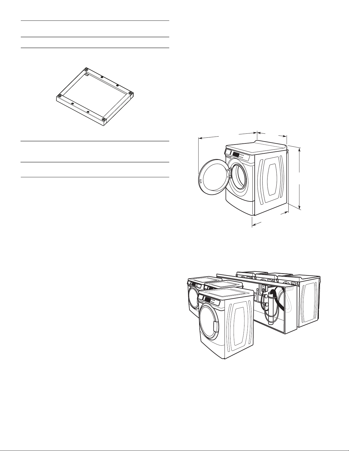
hose,
A BC
E
A. U-shaped hose form
B. Water inlet hoses (2)
C. Inlet hose washers (4)
D. Transit bolt hole plug (4)
E. Beaded tie strap
†® TORX is a registered trademark of Acument Intellectual Properties, LLC.
D
4
Options
Pedestal
You have the option of purchasing pedestals separately for this
washer. The pedestal will add to the total height of the washer.
Installation clearances
■ The location must be large enough to allow the washer door
to be fully opened.
■ Additional spacing should be considered for ease of
installation and servicing. The door opens more than 90°
and it is not reversible.
■ Additional clearances might be required for wall, door, and
floor moldings.
■ Additional spacing of 25 mm (1") on all sides of the washer
is recommended to reduce noise transfer.
■ Companion appliance spacing should also be considered.
■ When installed, the plug should be accessible for washer
disconnection from the mains supply.
Optional pedestal
Pedestal
Height
Approximate
ight
he
Color Part Number
with washer
(73 mm) 2
7
/8" (1207 mm) 47.5" White WHP0400VW
Location Requirements
Selecting the proper location for your washer improves
performance and minimizes noise and possible washer “walk.”
Your washer can be installed under a custom counter, or in a
basement,
Companion appliance location requirements should also be
considered. Proper installation is your responsibility.
You will need
■ A water heater set to deliver 60°C (140°F) water to the
■ An earthed electrical outlet located within 1.8 m (6 ft.) of
■ Hot and cold water taps located within 1.2 m (4 ft.)
■ A level floor with a maximum slope of 25 mm (1") under entire
■ A sturdy and solid floor to support the washer with a total
Do not operate your washer in temperatures below 0°C (32°F).
Some water can r
in low temperatures.
laundry room, or recessed area. See “Drain System.”
washer.
where the power cord is attached to the back of the washer.
See “Electrical Requirements.”
of the hot and cold water fill va
lves, and water pressure
of 137.9-689.6 kPa (20-100 psi).
washer. Installing the washer on soft floor surfaces, such as
carpets or surfaces with foam backing, is not recommended.
weight (water and load) of 180 kg (400 lbs).
emain in the washer and can cause damage
Washer Dimensions
1282 mm
1
(50
/2")
Door is not reversible.
686 mm
(27")
732 mm
13
/16")
(28
961 mm
5
(37
/6")
A floor drain should be provided under the bulkhead.
Prefabricated bulkheads with electrical outlets, water
inlet lines, and drain facilities should be used only where
local codes permit.
5
Drain System
The washer can be installed using the standpipe drain system
(floor or wall), the laundry tub drain system, or the floor drain
system. Select the drain hose installation method you need.
See “Tools and Parts.”
Standpipe drain system - wall or floor (views A & B)
The standpipe drain requires a minimum diameter standpipe of
50 mm (2"). The minimum carry-away
than 45.5 L (12 gal.) per minute.
The top of the standpipe must be at least 762 mm (30") high and
higher than 2.4 m (96") from the bottom of the washer.
no
762 mm
(30" min.)
A B
Laundry tub drain system (view C)
The laundry tub needs a minimum 76 L (20 gal.) capacity. The top
of the laundry tub must be at least 762 mm (30") above the floor.
Floor drain system (view D)
The floor drain system requires a siphon break that may be
purchased separately. See “Tools and Parts.”
The siphon break must be a minimum of 710 mm (28") from the
bottom of the washer. Additional hoses might be needed.
762 mm
(30" min.)
capacity can be no less
710 mm
(28" min.)
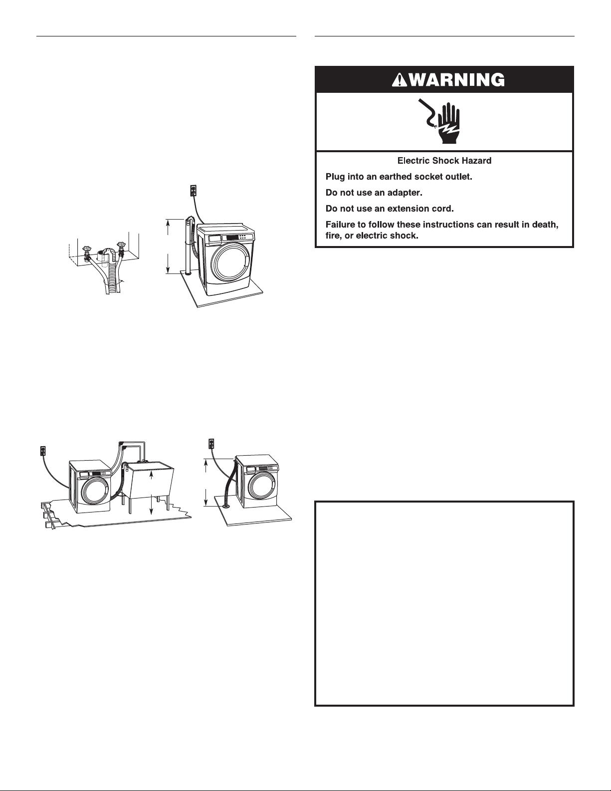
Electrical Requirements
■ A 220-240V, 50 Hz., fused electrical supply is required. A
time-delay 10-16A fuse or circuit breaker is recommended.
■ This washer is equipped with a power supply cord having an
earthed plug.
■ To minimize possible shock hazard, the cord must be
plugged into an earthed socket outlet, earthed in accordance
with local codes and ordinances. If a mating outlet is not
available, it is the personal responsibility and obligation of the
customer to have the properly earthed outlet installed by a
qualified electrician.
■ If codes permit and a separate earth wire is used, it is
recommended that a qualified electrician determine that the
earth path is adequate.
■ If the supply cord is damaged, it must be replaced by the
manufacturer, its service agent, or a qualified person to avoid
a hazard.
■ Do not earth to a gas pipe.
■ Check with a qualified electrician if you are not sure the
washer is properly earthed.
■ Do not have a fuse in the neutral or earth circuit.
EARTHING INSTRUCTIONS
This washer must be earthed. In the event of a malfunction
C D
6
or breakdown, earthing will reduce the risk of electric
shock by providing a path of least resistance for electric
current. This washer is equipped with a cord having an
equipment-earthing conductor and an earthing plug. The
plug must be plugged into an appropriate outlet that is
properly installed and earthed in accordance with all local
codes and ordinances.
WARNING:
Improper connection of the equipmentearthing conductor can result in a risk of electric shock.
Check with a qualied electrician or serviceman if you are in
doubt as to whether the appliance is properly earthed.
Do not modify the plug provided with the appliance – if it
will not t the outlet, have a proper outlet installed by a
qualied electrician.
INSTALLATION INSTRUCTIONS
Remove Transport System
WARNING
Excessive Weight Hazard
Use two or more people to move and install washer.
Failure to do so can result in back or other injury.
IMPORTANT: Position the washer so that the rear of the washer
is within approximately 900 mm (3 ft.) of its final location.
There are 4 shipping bolts in the rear panel of the washer that
support the suspension system during transportation. These
bolts also retain the power cord inside the washer until the bolts
are removed.
Power Cord Installation
1. Select the plug that fits with the electric receptacle.
2. Assemble the plug into the end of the power cord.
3. Secure the power cord by seating the connection on the cord
lock.
1. Keep the washer in the upright position while removing the
shipping bolts.
2. Using a 1/2
3. Once
completely pull out the bolt, including the plastic spacer
covering the bolt.
4. Once all 4 bolts are removed, discard the bolts and spacers.
Then push the power cord plug into the opening on the right
side of the rear panel and pull the power cord through the
opening on the left side of the rear panel and close holes with
the attached cap. Do not pull plug end of power cord through
the right side hole.
5. Close the bolt holes with the 4 transport bolt hole plugs. NOTE: If the wash
product distributor or installer. To avoid suspension and structural
damage, your washer must be properly set up for relocation by a
trained professional.
" wrench, loosen each of the bolts.
the bolt is loose, move it to the center of the hole and
er is to be transported at a later date, call your
4. Place the cord lock cover and push until it snaps.
ke sure the power cord connection is seated on the cord
5. Ma
lock and that the cord lock clamps correctly.
Connect the Inlet Hoses
Insert new flat washers (supplied) into each end of the inlet
hoses. Firmly seat the washers in the couplings.
A B
A. Coupling
B. Washer
■ Use the new inlet hoses supplied with washer. Do not re-use
old inlet hoses.
Connect the inlet hoses to the water taps
Make sure the washer drum is empty.
1. Attach
2. Attach
a hose to the hot water tap. Screw on coupling
by hand until it is seated on the washer.
a hose to the cold water tap. Screw on coupling
by hand until it is seated on the washer.
7
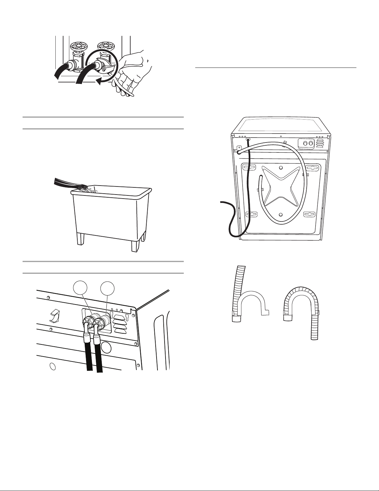
3. Using pliers, tighten the couplings with an additional
two-thirds turn.
NOTE: Do not overtighten or use tape or sealants on the tap.
Damage to the inlet hoses can result.
Clear water lines
■ Run water through both taps and inlet hoses, into a laundry
tub, drainpipe, or bucket, to get rid of particles in the water
lines that might clog the inlet valve screens.
■ Check the temperature of the water to make sure that the hot
water hose is connected to the hot water tap and that the
cold water hose is connected to the cold water tap.
4. T
urn on the water taps completely and check for leaks.
NOTE: Replace inlet hoses after 5 years of use to reduce the
risk of hose failure. Record hose installation or replacement
dates on the hoses for future reference.
Periodically inspect and replace hoses if bulges, kinks, cuts,
w
ear, or leaks are found.
Route the Drain Hose
Proper routing of the drain hose protects your floor from damage
due to water leakage. Read and follow these instructions.
Remove drain hose from the washer
Gently pull the corrugated drain hose from the shipping clips.
Connect the inlet hoses to the check valves on washer
H
H. Hot water inlet
C. Cold water inlet
1. Attach the hot water hose to the check valve on washer’s hot
(H) water inlet valve. Screw on coupling by hand until it is
seated on the check valve.
2. Attach th
cold (C) water inlet valve. Screw on coupling by hand until it is
seated on the check valve.
3. Using pliers, tigh
thirds turn.
NOTE: Do n
result.
e cold water hose to the check valve on washer’s
ten the couplings with an additional two-
ot overtighten. Damage to the coupling can
C
Laundry tub drain or standpipe drain
Connect the drain hose form to the corrugated d
A B
A. Snap either end of the drain hose for
at the point where the corrugation begins.
B. Bend drain hose over drain hose for
To keep drain water from going back into the washer:
■ Do not straighten the drain hose, do not force excess drain
hose into standpipe. Hose should be secure, but loose
enough to provide a gap for air.
■ Do not lay excess hose on the bottom of the laundry tub.
m to the drain hose
m and snap into place.
rain hose.
Floor drain
You may need additional parts. See Floor drain under “Tools
and Parts.”
8
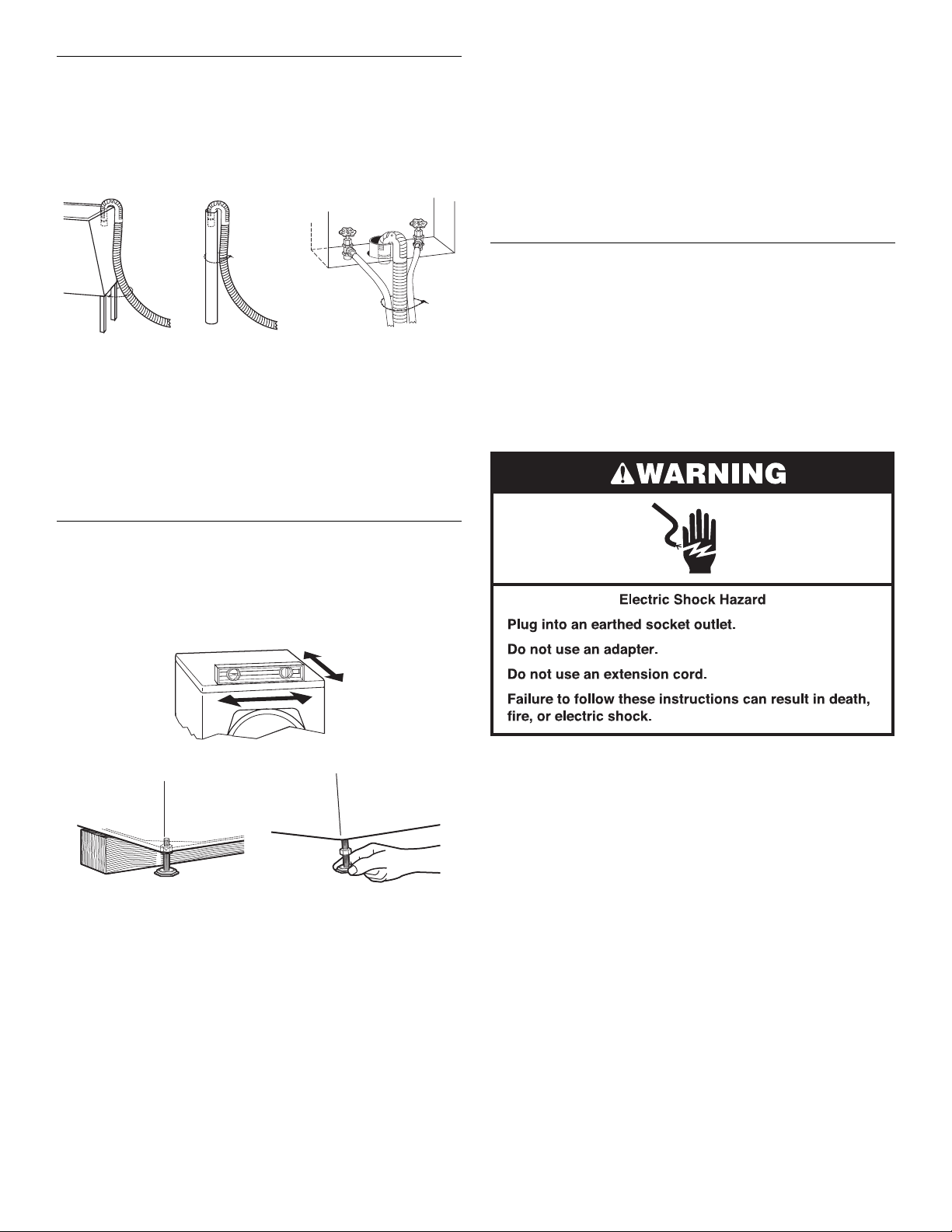
Secure the Drain Hose
1. Drape the power cord over the washer top.
2. Move the washer to its final location.
ce the drain hose in the laundry tub or standpipe as
3. Pla
shown. See illustrations A and B.
4. Sec
5. If the washer taps and the drain standpipe are recessed, put
NOTES:
■ Do not force excess drain hose back into the rear of the
■ To avoid siphoning, do not seal the drain hose into the
ure the drain hose using the supplied beaded tie strap.
A B C
the hooked end of the drain hose in the standpipe as shown.
See illustration C.
washer.
standpipe.
2. Ma
ke sure all four feet are stable and resting on the floor.
Check that the washer is level (use a level).
er the washer is level, use a 9/16" open-end wrench to turn
3. Aft
the nuts on the feet tightly against the washer cabinet.
IMPORTANT: All four fe
not tight against the washer cabinet, the washer may vibrate.
4. The washer should not move front to back, side to side, or
diagonally when pushed on its top edges.
5. Slid
6. Conf
e the washer to its final location.
irm the levelness of the washer.
et must be tightened. If the nuts are
Complete Installation
1. Check the electrical requirements. Be sure that you have the
correct electrical supply and the recommended earthing
method. See “Electrical Requirements.”
eck that all parts are now installed. If there is an extra part,
2. Ch
go back through the steps to see which step was skipped.
heck that you have all of your tools.
3. C
spose of/recycle all packaging materials.
4. Di
5. Check that the water taps are on.
6. Che
ck for leaks around taps and inlet hoses.
Level the Washer
Properly leveling your washer avoids excessive noise and
vibration.
1. Check
the levelness of the washer by placing a level on the
top edge of the washer, first side to side, then front to back.
If the washer is against a wall, move the washer out slightly
before tipping back. If the washer is not level, first prop the
front with a wood block and adjust the feet as necessary;
then prop the back and adjust feet as necessary. Repeat this
step until washer is level.
7. Plug into an earthed socket outlet.
8. To test and to clean your washer, measure 1/2 the detergent
manufacturer’s recommended amount for a medium-size
load. Pour the detergent into the detergent dispenser. Select
any cycle and allow the washer to complete one whole cycle.
9

CONTROL SET-UP INSTRUCTIONS
1. Door must be closed before cycle selection is made.
2. Press fabric setting key pad for the wash cycle desired. After
the cycle is started, the time will display and count down.
General Information
Scrolling ‘out of order’ showing in display, followed by a
failure code
This condition indicates the washer is inoperative.
“0 Minutes” showing in display
This condition indicates the washer cannot be operated. If a door
ch fails, it must be replaced before normal operation can be
swit
restored.
Cold Start (initial first use)
Washer is programmed at the factory as follows:
■ 9-minute wash period
■ 3 rinses (extra rinse not enabled)
Warm Start (after power failure)
A few seconds after power is restored, if a cycle was in progress
at th
e time of the power failure, “RESELECT CYCLE” will flash in
the display, indicating the need for a key press to restart washer.
Control Set-up Procedures
IMPORTANT: Read all instructions before operating.
Set-up procedures can be entered by
Code (see service Access Code section).
IMPORTANT: Unplug wa
opening the console. To access connector AA1:
Unplug
Open con
Plu
The washer is now in the set-up mod
key pads and the digital display are used to set up the controls.
The display can contain 4 numbers and/or letters and a decimal
point. These are used to indicate the set-up codes and related
code values available for use in programming the washer.
washer or disconnect power.
g in washer or reconnect power.
sher or disconnect power before
sole, disconnect plug on AA1, close console.
How to use the key pads to program controls
1. The PERM PRESS key pad is used to adjust the
values associated with set-up codes. Pr
will change the value by increments. Rapid adjustment
is possible by holding the key pad down.
2. The WOOLENS
codes. Pressing this key pad will advance you to the next
available set-up code. Holding the key pad down will
automatically advance through the set-up codes at a rate
of 1 per second.
key pad advances you through the set-up
using the Service Access
e. The lower fabric setting
essing this key pad
3. T
he DELICATES/KNITS key pad is used to select or deselect
options.
Start Operating Set-up
Before proceeding, it is worth noting that, despite all of the
options available, an owner can simply choose to un-crate a new
semi-pro washer, hook it up, plug it in, and have a washer that
operates. Washers are preset at the factory for a 9-minute wash
period and 3 rinses (no extra rinse).
Set-up Codes
■ The WOOLENS key pad will advance you from code to code.
■ The PERM PRESS key pad will change the code value.
■ The DELICATES/KNITS key pad will select or deselect
options.
The set-up code is indicated by the one or two left-hand
characters. The set-up code value is indicated by the two or
three right-hand characters.
CODE EXPLANATION
7 9 WASH LENGTH
7 9
8 00 ADDITIONAL RINSE OPTION
8800
9 00 CYCLE COUNTER OPTION
9900
This is the number of minutes for WASH. Washer
c
omes from the factory preset with 9 minutes.
Choose fr
PRESS key
Press the WOOLENS key pad once to advance
to next code.
This option is either SELECTED “ON” or
NOT SELECTED “OFF.”
Not Selected “OFF.”
Ar
Selected “ON.” Cannot be combined with the
Super Cycle rinse option.
Press the DELICATES/KNITS key pad once for this
selection.
Press the WOOLENS key pad once to advance
to next code.
This option is either SELECTED “ON” or
NOT SELECTED “OFF.”
Not Selected “OFF.”
0C
Selected “ON” and not able to be deselected.
Press the DELICATES/KNITS key pad
3 consecutive times to select “ON.” Once selected
“ON” it cannot
Press the WOOLENS key pad once to advance
to next code.
om 9-17 minutes by pressing the PERM
pad.
be deselected.
10

CODE EXPLANATION
5. 00 TIME-OF-DAY CLOCK, MINUTES
5. 00
6. 00 TIME-OF-DAY CLOCK, HOURS
6. 00
r. 800 TOP SPIN SPEED RPM
r. 800
A1. 00 PREWASH LENGTH
A1. 00
A2. 03 FINAL SPIN LENGTH
A2. 03
If cycle counter (9 0C) is selected, the
1 00 Number of cycles in
2 00 Number of cycles in ONES. 2
This is “VIEW ONLY” and cannot be cleared.
Pr
next code.
EXIT FROM SET-UP MODE
Remove power, open console, reinsert plug into AA1, close console,
apply power.
and
This is the TIME-OF-DAY CLOCK, minute setting;
select 0-59 minutes by pressing the PERM PRESS
key pad.
Press the WOOLENS key pad once to advance
to next code.
NOTE: Use
This is the TIME-OF-DAY CLOCK, hour setting;
select 0-23 hours by pressing the PERM PRESS
key pad.
Press the WOOLENS key pad once to advance
to next code.
This can be selected from the following spin
speeds: 600 rpm, 750 rpm, 800 rpm, 1000
(displa
ess the WOOLENS button once to advance to
essing the PERM PRESS key pad. Factory pre-
pr
set for 800 rpm.
Press the WOOLENS key pad once to advance
to next code.
This is the number of minutes of PREWASH.
C
hoose 0 to disable the prewash or
2 and 7 minutes by pressing the PERM PRESS key
pad.
Press the WOOLENS key pad once to advance
to next code.
This is the number of minutes of final high speed
spin.
P
ERM PRESS key pad.
Press the WOOLENS key pad once to advance
to next code.
HU
s the 24 hr. clock
ys as 999) rpm. Step between speeds by
select between
Choose from 3-8 minutes by pressing the
following is true:
1 02 = 200
NDREDS.
TOTAL CYCLES = 225 cycles
25 = 25
Washer Diagnostic Mode
To enter the “Washer Diagnostic Mode,” first enter “Start
Operating Set-up.” Then press and hold the DELICATES/KNITS
key pad for 1 second while in set-up code 6, anytime a
diagnostic code is present.
On entry to diagnostic mode the
cycle in process is canceled, money in escrow is cleared, and
dia
gnostic codes are cleared. If a diagnostic code persists,
it must be corrected before the following cycle options
are permitted.
There are five possible ways to initiate cycle activity from
diagnostic mode as follows:
asher Cleanout cycle - With the entire display flashing, this
1. W
cycle is started by pressing the BRIGHTS key pad.
Use the Washer Cleanout cycle once a month to keep the
in
side of your washer fresh and clean. This cycle uses a
higher water level. Use with liquid chlorine bleach to
thoroughly clean the inside of the washer. This cycle should
not be interrupted.
IMPORTANT: Do not place garments or
washer during the Washer Cleanout cycle. Use this cycle with
an empty wash drum.
2. Manual Overview T
cycle is started by pressing the WHITES key pad. This cycle
provides more typical full length fills, tumbles, drains, and
actuator dispenser movement, allowing for a more thorough
analysis of the washer operation, including pressure switch
behavior.
3. Quick
4. Quick Overview Test - With the entire display flashing, this
Pressing the DELICATES/KNITS key pad will exit diagnostic
mode and cancel a diagnostic
Spin Cycle - With the entire display flashing, this cycle
is started by pressing the COLORS key pad. This cycle
provides a method to quickly drain and spin (remove water
from the washer) if desired.
cycle is started by pressing the WOOLENS key pad. This
cycle provides a quick verification that the cold and hot water
valves, dispensers, and pump motor are working, as well as
actuator dispenser movement. It also includes door lock,
drain, and spin operations.
est - With the entire display flashing, this
DIAGNOSTIC CODES
If one of the following has occurred, the appropriate diagnostic
code will be in the display.
d9 Low voltage detected for 8 seconds.
F20 Slow Fill. The washer will not detect water input for
4 min. Pressure switch failure or no water inlet. This
cod
e is reported as d8 on d7.
F22 The door is not able to lock. Door lock error or
someon
door switch with their finger.
(For any other display consult service personnel)
e trying to start the washer, by pressing the
entire display will flash, a
other items in the
cycle in process.
11

SERVICE ACCESS CODE
This code can be entered to access service mode without
removing the console. It only functions on washers set up for 0
vend price without any Special Pricing set-up, and the Coin/Debit
Option must be set to “J._d”. If the washer is not in failure mode,
the door must be opened to proceed. Service Access Code
contains 6 steps and some are timed. Using only the three bottom
buttons (numbered 1, 2, and 3 from left to right):
ress 2 for longer than 2 seconds but less than 10 seconds.
1. P
2. Press 1 & 3 together for 2 seconds, then release. Displays S 3.
3. Press 1 & 2 together, then release. Displays S 4.
ess 2 & 3 together, then release. Displays S 5.
4. Pr
5. Press 2, then release. Display shows “codE”.
6. Wait at least 2 seconds, but not more than 15 seconds, then
press in succession: 3, 2, 1, 3.
NOTE: If
properly, as noted above, there is a 15 second delay before it can
be attempted again.
When the Service Access Code is used, there are 3 options
to exit.
1. Fr
2. Wait 2 minutes without touching any keypads (without
the Service Access Code procedure is not completed
om Set-up Code 8, press key #1 for 4 seconds.
diagnostic modes running).
WASHER CARE
3. Power down the washer, then reapply power.
WASHER HELP MODE
This mode is entered by pressing the PERM PRESS key pad
while in Set-up option code 2.XX.
In help mode, other display symb
to reflect the state of various inputs a
Display Symbol Description
Wash Water sensed at wash level.
*
° (Circle above digit) Door closed.
DOOR LOCKED Door sensed locked.
COLD Cold water relay on.
HOT Hot water relay on.
OR Door unlock.
AVAILABLE Drain pump ON.
ols and elements are mapped
nd outputs as follows:
Low voltage present (below about
90 VAC).
Cleaning Your Washer
Cleaning the Door Seal/Bellow
1. Open the washer door and remove any clothing or items from
the washer.
2. Inspect
3. If stained areas are found, wipe down these areas of the
IMPORTANT:
■ Wear rubber gloves when cleaning for prolonged periods.
■ Refer to the bleach manufacturer’s instructions for proper
the colored seal/bellow between the door opening
and the drum for stained areas. Pull back the seal/bellow to
inspect all areas under the seal/bellow and to check for
foreign objects.
A
A. Seal/Bellow
seal/bellow, using the procedure that follows.
a) Mi
x a dilute solution, using 177 mL (3/4 cup) of liquid
chlorine bleach, and 3.8 L (1 gal.) of warm tap water.
b) Wipe the
using a damp cloth.
c) Let stand 5 minutes.
d) Wipe down area thoroughly with a dry cloth and let the
washer interior air dry with door open.
use.
seal/bellow area with the dilute solution,
Washer Maintenance Procedure
This washer has a special cycle that uses higher water volumes in
combination with liquid chlorine bleach to thoroughly clean the
inside of the washer.
NOTES:
■ Read these instructions completely before beginning the
cleaning process.
■ If necessary, the cleaning cycle may be interrupted by
pressing the DELICATES/KNITS button twice. However, this
will not immediately stop the cycle. The washer will continue
with several rinse and drain steps to ensure that all remaining
bleach is rinsed from the washer.
Begin procedure
1. Open the washer door and remove any clothing or items from
the washer.
2. Use liquid chlorine bleach:
Open the dispenser drawer and immediately
160 mL (2/3 cup) of liquid chlorine bleach to the bleach
compartm
NOTE: Do
than 160 mL (2/3 cup) of bleach will cause pr
over time.
3. Close
4. To start the Clean Washer cycle, first enter “Start Operating
Set-up.” Then press and hold DELICATES/KNITS for
1 second. With the entire displa
NOTE: Th
again, and then the cycle will continue.
■ The washer will not fill, but the drum will rotate while the
ent.
not add any detergent to this cycle. Use of more
the washer door and the dispenser drawer.
y flashing, press BRIGHTS.
e drum will rotate, then the door will unlock, lock
washer runs a short sensing cycle. This will take
approximately 3 minutes.
add
oduct damage
12

5. The cycle will determine whether clothing or other items are
in the washer.
If no items are detected in the washer, it will proceed
a)
to Step 7.
b) If any items are detected in the washer, “rL” or “F-34”
will be displayed. Then
■ Press DELICATES/KNITS to cancel the failure code.
Then repeat steps 1, 3, and 4 to start the cycle again.
6. Once
7. Afte
the cycle has begun, allow the cycle to complete.
r the cycle is complete, leave the door open slightly,
to allow for better ventilation and drying of washer i
the door will unlock.
nterior.
Cleaning the dispenser drawer
The dispenser drawer is removable for easy cleaning.
1. Unlock the
Remove the drawer.
2. Remove the
compartments).
3. W
ash the parts under running water.
NOTE: D
eplace the inserts and return the dispenser to the drawer.
4. R
dispenser drawer by pressing the Release Lever.
inserts (the siphon from the softener and bleach
o not wash components in the dishwasher.
Always do the following to maintain washer freshness
■ Use only detergent for automatic washer.
■ Leave the door slightly open after each cycle to allow for
better ventilation and drying of washer interior.
■ Clean the washer monthly using the Washer Maintenance
Procedure, 160 mL (2/3 cup) of liquid chlorine bleach.
■ If the procedure does not sufficiently improve the washer
freshness, please evaluate your installation and usage
conditions for other causes.
Cleaning the exterior
Use a soft damp cloth or sponge to wipe up any spills.
Occasionally wipe the outside of your washer to keep it looking
new. Use mild soap and water. Do not use abrasive products.
Water Inlet Hoses
Replace inlet hoses after 5 years of use to reduce the risk of hose
failure. Periodically inspect and replace inlet hoses if bulges,
kinks, cuts, wear, or leaks are found.
When replacing your inlet hoses, record the date of replacement.
ASSISTANCE OR SERVICE
If you need further assistance, you can contact the dealer/distributor
where the washer was purchased.
When you call, you will need the washer model number
number. Both numbers can be found on the serial-rating plate
located on your washer.
For Warranty Terms and Conditions contact the dealer/distributor.
and serial
13
SECURITE DU LAVE-LINGE
Votre sécurité et celle des autres est très importante.
Nous donnons de nombreux messages de sécurité importants dans ce manuel et sur votre appareil ménager. Assurez-vous de
toujours lire tous les messages de sécurité et de vous y conformer.
Voici le symbole d’alerte de sécurité.
Ce symbole d’alerte de sécurité vous signale les dangers potentiels de décès et de blessures graves à vous
et à d’autres.
Tous les messages de sécurité suivront le symbole d’alerte de sécurité et le mot “DANGER” ou
“AVERTISSEMENT”. Ces mots signient :
Risque possible de décès ou de blessure grave si vous ne
DANGER
AVERTISSEMENT
Tous les messages de sécurité vous diront quel est le danger potentiel et vous disent comment réduire le risque de blessure et
ce qui peut se produire en cas de non-respect des instructions.
suivez pas immédiatement les instructions.
Risque possible de décès ou de blessure grave si vous
ne suivez pas les instructions.
14
MISE AU REBUT DU LAVE-LINGE
EXIGENCES D’INSTALLATION
Outillage et pièces
Rassembler les outils et pièces nécessaires avant de commencer
l'installation. Les pièces fournies se trouvent dans le tambour du
lave-linge.
Outils nécessaires au raccordement des tuyaux d'arrivée d'eau
■ Pince (ouverture jusqu'à
39,5 mm [1
9
/16"])
Outils nécessaires à l'installation
■ Clés plates de 1/2" et 9/16"
■ Tournevis de sécurité
■ Tourne-écrou de 1/4"
Pièces fournies
To rx
®†
T-20
■ Lampe de poche
(facultative)
■ Niveau
■ Cale en bois
■ Règle ou mètre ruban
Autres pièces
Il se peut que l'installation nécessite des pièces supplémentaires.
Pour acheter l'un des articles indiqués ici, contacter votre
concessionnaire Whirlpool agréé.
Si vous avez Vous devrez acheter
Evier de buanderie
ou tuyau rigide de
rejet à l'égout plus
haut que 2,4 m
(96")
Egout surélevé Evier de vidange standard de 76 L
Egout au plancher Brise-siphon, pièce n° 285320; tuyau de
Tuyau de vidange
op court
tr
Système de pompe de puisard (si non
déjà disponible)
(20 gal.) de 762 mm (30") de hauteur ou
évier utilitair
(disponibles chez votre fournisseur local
d'articles de plomberie)
vidange
ensemble de système de vidange au
plancher, pièce n° 280129
Trousse de rallonge du tuyau de vidange
de 1,2 m (4 pi), pièce n° 285834
e et pompe de puisard
additionnel, pièce n° 8318155; et
A BC
D
E
A. Bride de retenue pour tuyau de vidange (en forme de U)
B. Tuyaux d'arrivée d'eau (2)
C. Rondelles pour tuyau d'arrivée d'eau (4)
D. Bouchons d'obturation des boulons de trans
E. Courroie perlée
port (4)
†® TORX est une marque déposée de Acument Intellectual Properties, LLC.
15
 Loading...