


hisialkitkHi liiiiiriiclkNis
ELEQRK SET-IN
UNIT
(STARTING WITH 1982 MODELS)
Part No. 311433 Rev. C
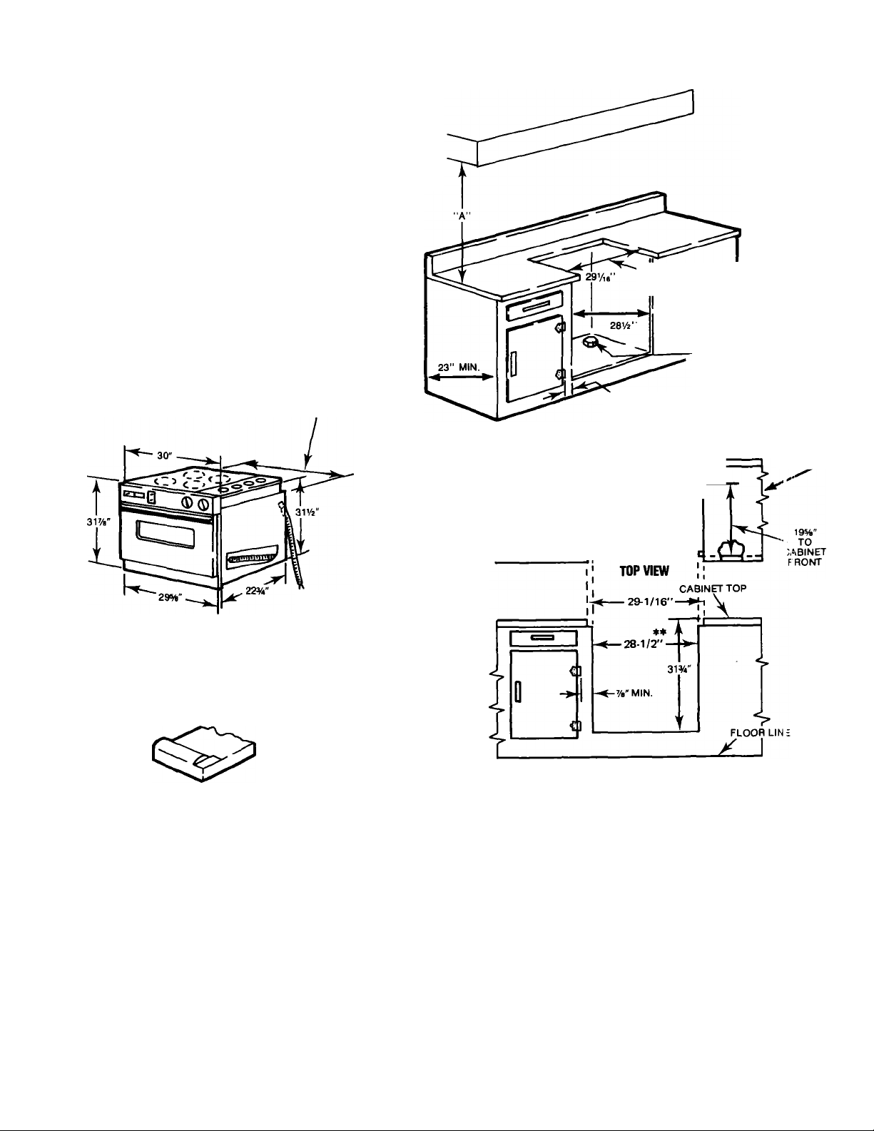
■ A" = 30" MIN. CLEARANCE BETWEEN
THE TOP OF THE COOKING PLATFORM
AND THE BOTTOM OF AN UNPROTECTED
WOOD OR METAL CABINET.
"A" = 24" MIN. WHEN BOTTOM OF WOOD
OR METAL CABINET IS PROTECTED BY
NOT LESS THAN FLAME RETARDANT
MILLBOARD COVERED WITH NOT LESS
THAN NO. 28 MSG. SHEET STEEL, 0.015"
STAINLESS STEEL, 0.024" ALUMINUM OR
0.020" COPPER.
CAUTION: To eliminate the hazard of reaching over
heated surface units, cabinet storage space located
above the surface units should be avoided. If cabinet
storage is to be provided, the hazard can be reduced by
installing a range hood that projects horizontally a
minimum of 5 inches beyond the bottom of the cabinets.
FOR COUNTERTOP AND CABI JET FRONT
CUT-OUT DIMENSIONS —SEi: F RONT AND
TOP VIEWS OF CABINET SHO' VN BELOW
LOCATE electrical
SUPPLY JUNCTION IlOX
ON FLOOR OR 0 J
REAR WALL NEA 1
FLOOR LINE.
28%" WRAP TO WRAP
INCLUDING SCREW HEADS
NOTE: ON CABINET TOPS WITH
FORMED FRONT EDGE, SHAVE
RAISED SECTION TO CLEAR
30" WIDE RIM. (SEE SKETCH BELOW)
48" CABLE
28-1/2" MINIMUM. IF 28-5/8"
IS AVAILABLE THE CUTOUT
SHOULD BE MADE 28-5/8".
FIGURE 1-ROUGH-IN DIMENSIONS
23"
T FRONT
i
CABINET
FRONT
%" MIN. REQUIRED BETWEEN
CUTOUT AND HINGE OR DOOR
WALL LINE
^
___________
COUNTEFtTOP OPENING
i
----
29-1/16"—i
CABINET OPENING ♦*
-28-1/2'
FRONT VIEW
C JJNTERTOP
NOTE:
The Installation must conform to any local codes. The
Set-In Unit may be mounted and secured to the cabinet
similar to regular built-in equipment.
1. CARPENTRY
Prepare the cut-out space, shown in
desired location in the counter top and cabinet. The
support surface
(AVz”
high) must be solid and level from
side to side and front to rear. A minimum of %” of
cabinet area on either side of cut-out should be clear
of handles, hinges or any other obstruction.
Figure 1,
in the
2. ELECTRICAL REQUIREMENTS
IMPORTANT: OBSERVE ALL GOVERNING CODES
AND ORDINANCES
SAVE THESE INSTRUCTIONS FOR THE LOCAL
ELECTRICAL INSPECTOR'S USE
A. A three-wire or four-wire single phase 120/240 vo t
60Hz AC only electrical supply (or three-wire cr
four-wire 120/208 volt if specified on nameplate) ii >
required on a separate circuit fused on both side;
of the line (time-delay fuse or circuit breaker Ii >
recommended). Do NOT fuse neutral. The fuse siz:;
must not exceed the circuit rating of the appliance;
specified on the nameplate.
NOTE: Wire sizes and connections must conforn
with the fuse size and rating of the appliance i i
accordance with the National Electrical Code an( 1
local codes and ordinances. Do not use an
extension cord.