

Page 1

Instaligtion Instructions
Part No. 3149595
IMPORTANT
Installer; Leave Installation Instructions
with the homeowner.
Homeowner: Keep Installation Instructions
for future reference.
Save Installation Instructions for local
electrical inspector's use.
30 " Electric
Double Oven
Page 2

Before you start..
Proper ¡r^staiiation is your
responsibiiiiy A qualified
technician should install this
even. Make sure you have
everything necessary for
■^.stoi'ation It IS the
'Gsponsibiiity of the instaüer to
coiT-piy vylth the msta'lation
c'earance specified on the
sericl/rating plate. The serial/
rating plate can be found
behind the upper oven door
on the oven frame.
Cheok .bcotion whore the
double oven v/iii be installed
T"^e looation should be away
from strong draft areas, such as
windows, doors, and strong
heating vents or fans The
couple oven should be
located for convenient use in
the kitchen.
Cabinet opening dimensions
that are shovyn must be used.
Given dimensions provide O'
olecrance. Dimensions given
c^e for a double oven siding on
a oontaot surface 2-2>!A' below
the open, lower oven door
height. The contact surtoce
must be solid and level and
flush v/ith the bottom of the
coDinet opening
Electrical ground is
required. See "Electric
requirements '
Note: Clearances
specified are for
combustible walls ona
materials that have a
density of 20 or mo^e
pounds per cubic foot No
evaluation of clearances
has been made for
installations adjacent to
materials that are less
than 20 pounds per cubic
foot or to plastic tiles and
sheeting
Important: observe
all governing codes
and ordinances,
The recessed installation ar-ea
must p.mvide oompiete
enoiosure around the recessed
bcrticn of the oven.
AWARNING
Electrical Shock Hazard
It is the customer's responsibility:
• To contact a qualified electrical
installer.
• To assure that the electrical
installation is adequate and in
conformance with National
Electrical Code ANSI/NFPA 70latest edition*, and all local
codes and ordinances.
Failure to do so could result in fire,
electrical shock or other personal
injury.
ACAUTION
Personal Injury/Product
• Do Not block oven vent.
• Securely fasten oven to cabinets
Failure to do so could cause the
oven to move or tip during use
and result in personal injury or
product damage.
Mobile home installation
The installation of this oven must
conform to the Manufactured Home
Construction and Safety Standards,
Title 24 CFR, Part 3280 (formerly the
Federal Standard for Mobile Home
Construction and Safety, Title 24,
HUD, Part 280).
A four-wire, power supply cord must
be used in a mobile home
installation, The appliance wiring will
need to be revised, See "Electrical
requirements', Figure 4, Panel B,
Panel A
Damage Hazard
Blocking the vent could result in
poor baking performance and
damage lo the cabinet.
using the eight screws provided.
Copies of the standards listed may
be obtained from:
' Notional Fire Protection Association
Battery March Park
Quincy, Massachusetts 02169
Tools needed for
installation:
requirements
Electrical ground is required on this
appliance.
AWARNING
Eleclrical Shock Hazard
• Eleclrical ground is required on
Ihis appliance.
• Improper conneclion ol Ihe
equipment-grounding
conductor con result in o fire,
eleclrical shock or other
personal injury.
• Check with o qualified
electrician il you ore in doubt os
to whether Ihe appliance is
properly grounded.
• Do Not use on extension cord
with Ihis appliance. Such use
may result in o fire, electrical
shock, or other personal injury.
• Do Not hove o luse in the neutral
or grounding circuit. This could
result in on eleclrical shock.
Save Installation instructions for
Ihe local electrical inspector's use.
A three-wire or four-wire,
■ single phase, 120/240-volt,
A
60-Hz, AC only, electrical supply (or
three-wire or four-wire, 120/208-volt if
specified on the nameplate) Is
required on a separate, 30-cmpere
circuit, fused on both sides of the
line, (time-delay or circuit breaker Is
recommended.)
The fuse size must not exceed the
circuit rating of the opplionce
specified on the serlal/roting plate.
The seriol/rotlng plate is located on
the cabinet behind the upper oven
door.
THE OVEN MUST BE
■ CONNECTED WITH COPPER
B
WIRE ONLY. Aluminum wire must Not
be used to avoid potentially
unsatisfactory connections.
Wire sizes (COPPER WIRE
■ ONLY) and connections
C
must conform to the requirements of
the National Electrical Code ANSI/
NFPA 70-latest edition', and all local
codes and ordinances for the
kilowatt rating of the oven,
The appliance should be
■ connected directly to the
D
fused disconnect or circuit breaker
box through flexible, ormored or
non-metollic sheathed copper cable
(with a grounding wire). The flexible,
armored cable extending from the
appliance should be connected
directly to the junction box.
Locate the junction box to
■ allow as much slack as
E
possible between the junction box
and the appliance so that the oven
con be moved if servicing is ever
necessary. Do Not cut the conduit.
Page 3
a 3/4", U.L-listed strain relief
must be provided at the
F
" junction box.
it is the persohdi
■ responsibiiity and obiigation
G
of the customer to contact a
quaiified eiectrician to assure that
the eiectrioai instdiiation is adequate
and in conformance with the
National Eiectricdi Code ANSI/NFPA
70-idtest edition, and ali local codes
and ordinances.
’ Copies of the stondard listed may
be obtained from;
Notional fire Protection Association
Battery March Park
Quincy, Massachusetts 02169
A wiring diagram is included
■ in the Tech-sheet (located
H
behind the air grille) with
self-cleaning ovens. For other
models, the wiring diagram is
located on the back, right-hand side
of the oven.
Electrical
connection
Elecfhcal ground is required on this
appliance.
AWARNING
Electrical Shock Hazard
’ Do Not connect appliance to
electrical supply until appliance
is permanenlly grounded.
’ Disconnect power to the junction
box before making the electrical
connection.
* This appliance must be
connected to a grounded,
metallic, permanent wiring
system, or a grounding
conductor should be connected
to the grounding terminal or lead
on the appliance.
Failure to follow these instructions
could result in a fire, personal
injury, or electrical shock.
This appliance is manufactured with
the neutral (white) power supply
wire and a cabinet-connected
grounding wire (green) twisted
fogether.
Connect the appliance cable to the
junction box through the 3/4“,
U.L.-listed strain relief. Complete the
electrical connection according to
local codes and ordinonces.
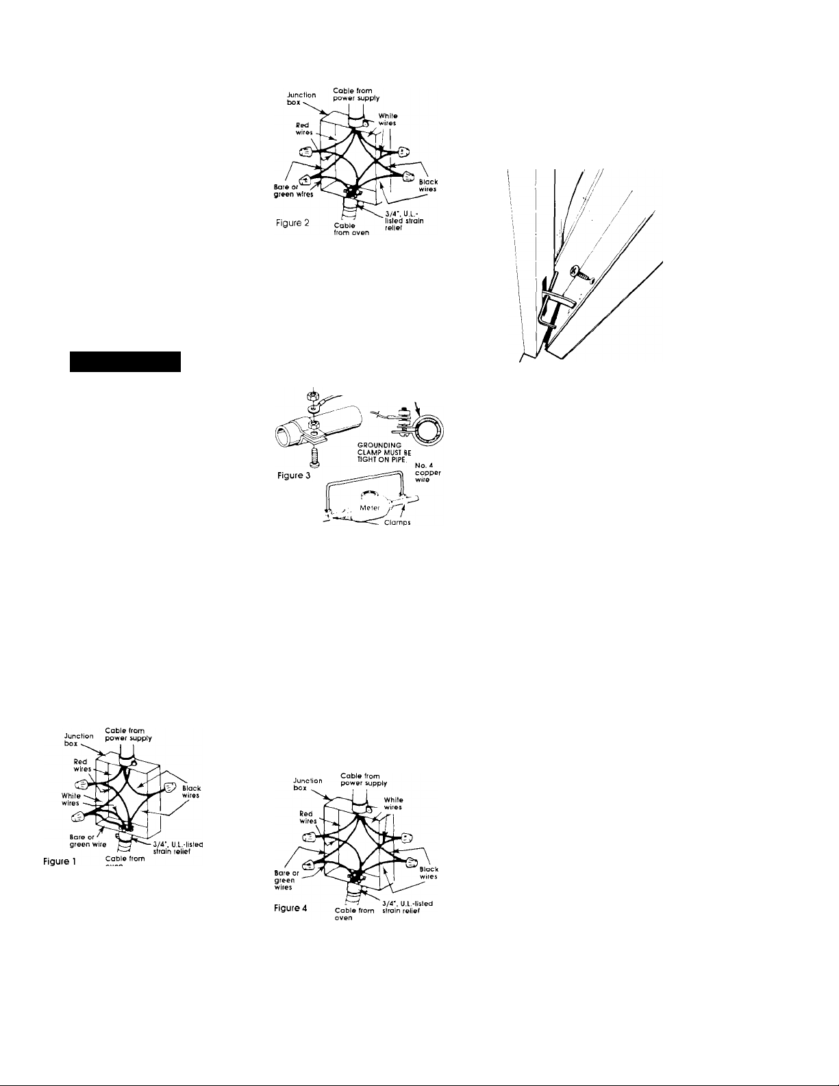
A. Where local codes permit...
Connectihg the cabinet-grounding
conductor to the neutral (white)
junction box wire:
B. Where local codes Do Not
permil...
Connecting the cabinet-grounding
conductor to the neutral (white)
junction box wire:
1. Separate the green (or bare) and
white appliance cable wires.
2. Connect the white appliance
cable wire with the neutral (white)
wire in the junction box,
3. Connect the two black wires;
then connect the two red wires.
(See Figure 2 )
4. Connect the grounding wire to a
grounded wire in the junction box
or to a grounded, copper, cold
water pipe’.
Tlghlen
nuts firmly. J ' Grounded cold
Melai cold
water pipe
Copper
' — (remove paint etc,)
water pipe
A
6. A separate, copper grounding
wire (No. 10 minimum) must be
connected to a grounded, cold
water pipe by means of a clamp
and then to the external grounding
connector screw. Do Not ground to
a gas supply pipe or hot water pipe.
Do Not connect to the electrical
supply until appliance is
permanently grounded,
* Grouniped cold water pipe must have
mefol continuity to electrical ground and not
be interrupted by plastic, rubber or other
electrical insulating connectors such as
hoses, fiftings, wosners or gaskets (including
water meter or pump). Any electrical
insulating connector should be jumped, as
shown, with o length of No 4 copper v/ire
securely clampea to bare metal al both
ends.
C. If connecting to a tour-wire
electrical system...
Do Not cohhect the cobihetgrouhding conductor to the neutral
(white) wire in the junction box.
Now start...
With oven in kitchen...
Remove shipping materials,
■ tape and protective film from
1
oven. Do Not remove the shipping
base at this time.
Remove the racks and
■ other ports from inside the
2
oven. Remove the dir grille taped to
the top or side of the oven.
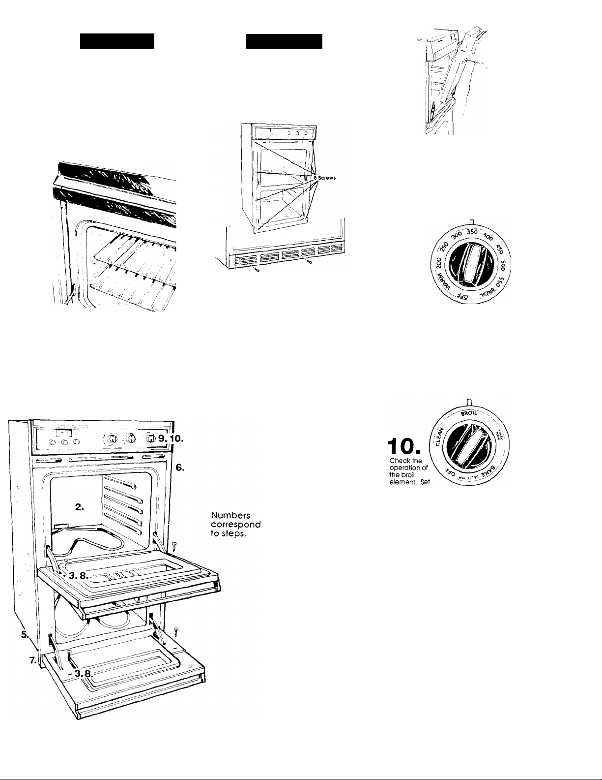
Upper oven door: Remove
■ the screws on each side of
3
the inner panel of the oven door.
Insert a nail (or an equivalent. 5/32"
diameter item) into the hole In each
of the hinges. Close the door as far
as possible. Lift the oven door off of
the hinges. Set aside.
Lower oven door: Open the oven
door to the broil '"stop" position and
lift door upwards to remove. Set
oven door aside.
1. Connect together three wires: the
green (or bare) and white appliance
cable wires with the neutral (white)
wire in the junction box,
2. Connect the two black wires; then
the two red wires, (See Figure 1,)
Panel B
1. Separate the green (or bore) and
white appliance cable wires.
2. Connect the white oppliance
cable wire to the neutral (white)
wire in the junction box,
3. Connect the two black wires; then
connect the two red wires, (See
Figure 4.)
4. Connect the green appliance
cable wire to the green grounding
wire in the junction box
Page 4
ACAUnON
Keep shipping base under oven
when moving across floor.
Failure to do so may cause
damage to floor covering,
4
"Electrical requirements' and
"Electrical connection' sections.
Panels A and B, for details.
5
opening as an area to grip. Thread
coble through opening in cabinet.
Floor Damage
Move over^ close to cabinet
■ opening. Make the
electrical connection. See
Re move and discard the
■ shipping base. Lift oven up
into cabinet opening using the oven
ACAUTION
Personal Injury/Producl
Damage Hazard
Securely fasten oven lo cabinets
using the eight screws provided.
Failure to do so could cause the
oven to move or tip during use
and result in personal injury or
product damage.
Center oven in cabinet
■ cutout. Secure oven to
6
cabinet using eight screws through
the mounting holes in the front frame
of the oven.
Put the air griile in place
■ beiow the iower oven
7
opening, making sure that the
louvers in the air grille point down,
the flange is at the bottom, and the
mounting holes are at the top, Slide
the air grille into position and attach
it to the oven cabinet with the three,
black or chrome, metal screws
provided.
Repidce the upper oven
door by fitting both corners
8.
of the door over the ends of the
hinges. Push the door evenly and
completely onto the hinges.
Remove the nails from the hinges.
Reinstall two screws in the Inner door
panel. Close the oven door. If the
door does not close, you have not
pushed the door completely onto
the hinges. Repeat for the lower
oven door.
Turn on
power
supply.
Check the
operation of
the oven
elements. Set
the oven selector
control knob to "BAKE", O’heoven
selector control knob is not available
on all models.) Set the oven
temperature control knob to 350°F.
The bottom element should glow red
and the indicator light should be on.
The upper element should become
hot, but not glow red. The oven ’
indicator light goes off when the
oven Is preheated. Repeat for the
lower oven.
Panel C
the oven selector
and oven temperoture control knobs
to "BROIL", (The oven selector
control knob is not available on all
models.) The top element should
glow red and the indicator light
should be on. Repeat for the lower
oven broil element.
You have just finished
Installing your new
Whirlpool oven. To get the
most efficient use from your new
oven, read your Whirlpool Use
and Care Guide. Keep Installation
Congratulations!
Instructions and Guide close to oven j
, lor easy reference. The Insfruclions /
will make reinstalling your
Whirlpool oven in another
home os easy os the
first installalion.
Page 5

If the oven does
not operate...
Check that the circuit breaker is not
tripped or the fuse biown. A more
detaiied, troubie-shooting checkiist is
provided in the Use and
Care Guide.
If you need assistance...
During normal business hours, the
Whirlpool COOL-LINE® Service will
answer any questions about
operating and maintaining your
oven not covered in the Installation
Instructions. The Whirlpool
COOL-LINE® Service telephone
number is (800) 253-1301. Dial just as
you normally dial long distance —
the call is free, When you call, you
need the oven model number and
serial number. Both numbers can be
found on the serial/rating plate
located on the frame behind the
oven door.
If you need service...
In the event your Whirlpool
appliance should need service, call
the dealer from whom you
purchased the appliance or a
Whirlpool franchised TECH-CARE®
service company. He is in the Yellow
Pages of your telephone directory
listed under "Appliances —
Household — Major — Service or
Repair". You can also obtain his
name and number by dialing, free,
within the continental United States,
the Whirlpool COOL-LINE® Service
number, (800) 253-1301, Aspecial
operator will tell you the name and
telephone number of your nearest
Whirlpool TECH-CARE® service outlet.
Maintain the quality built into your
Whirlpool appliance — call
TECH-CARE® service.
Part No 3149595
© 1989 Whirlpool Corporation
Whirlpool
PiGOGiGG oy Whi'ipoci Ccrpo'otion. Beoton Harbor, Michigan 49022
^ CORPORATION
P' n:od I
 Loading...