


R 1604/2004 OPERATING MANUAL

.1. |
R1604 & R2004 |
R Series Mixers |
Introduction
Thank you for purchasing an R1604/2004 Mixer from Wharfedale Professional. Please read these instructions carefully to ensure problem free operation and user satisfaction.The R Series of mixers from Wharfedale Professional are designed to offer a superior quality audio performance in an easy to use, great value package. The quality of the R Series is such it can be used in a variety of professional applications such as studio, sound reinforcement, field recording and film/video production.
Features R1604/2004:
*4(R1604)/8(R2004) balanced/unbalanced mono line input
*4(R1604)/8(R2004) low noise, high headroom XLR mic inputs
*4 pairs of balanced/unbalanced stereo line inputs with +4/-10 input gain/sensitivity selector
*Insert facility on all mono channels (R2004 only)
*48V DC global phantom power
*3- band EQs with semi-parametric mids in all mono input channels (R2004 only)
*3- band EQs in all input channels (12kHz, 2.5kHz, 80Hz)
*75Hz, 18dB/octave low cut filter on mono input channels
*PFL/SOLO and Mute/ALT 3-4 on all channels
*ALT 3-4 extra stereo bus
*2 stereo EFX returns
*EFX to Main, ALT 3-4 and AUX 1 switch
*Balanced inputs and outputs
*Peak and signal LEDs on mono channel
*Two AUX send (Pre and Post fader switch on AUX 1)
*Separate main mix, ALT3-4, control room and headphone outputs
*2 track inputs assignable to main mix, control room/headphone outputs
*Highly accurate 10 segment bargraph meters
*High quality 60mm faders
,,
* 19 Rack Mounting kit included

R Series Mixers |
R1604 & R2004 |
.2. |
Getting Started
1. Power Supply
The R Series mixer is supplied with an external power supply unit. Only use the power supply provided with your mixer. Connect the R Series mixer to the power supply unit and THEN connect the power supply unit to the Mains. During long periods of operation the mixer may become warm. Therefore it is important that the unit is placed where the air is able to flow freely around it. The power supply is factory set to the correct voltage and this can be checked by referring to the label on the unit. If the mixer is used in a country having a different supply voltage then a new power supply will be required and you should consult your dealer.
2. Packing
Every care has been taken to ensure that your mixer reaches you in perfect condition and working order. The exterior and internal packaging has been designed to protect the unit in transit, but should you notice any damage to the unit, please notify the place of purchase immediately.
3. Safety
Avoid the excessive heat, humidity, dust and vibration: Keep the unit away from locations where it is likely to be exposed to high temperature or humidity, such as near radiators, stoves, etc. Also avoid locations which are subjected to excessive dust accumulation, or to vibration that could cause mechanical damage.
Avoid physical shocks: Strong physical shocks to the unit may cause damage. Handle the unit
with care.
Do not open the case to attempt to repairs or modifications yourself: contains no user-serviceable parts. Refer all maintenance to qualified service personnel.
Always power off before making connections: Always turn the AC mains OFF before connecting cables. This is important to prevent damage to the unit itself as well as other connected equipment.
4. Warranty
The R Series mixers warranty covers any defects in the manufacture of the product for a period of 12 months from the date of purchase. The Warranty is non-transferable and applies to the original purchaser only. Should you have any Warranty issues, please contact your place of purchase who will advise on a returns procedure.
.3. R1604 & R2004 R Series Mixers
Features of the R Series Mixer
Mono Input Channels:
 1
1
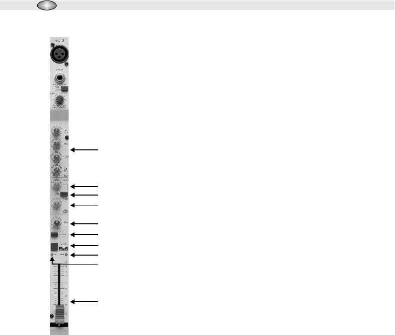
1. Low Impedance (or Low Z) Mic Inputs
The low noise, high headroom Low Z mic inputs for use with balanced or
 2
2
low impedance microphones or low level external equipment with XLR
 3
3
connectors.
 4
4
2.Line Inputs
The features of balanced/unbalanced high impedance mono line inputs for
,,
use with high level signals with1/4 phone plug connectors.
|
3. Low Cut Filter |
|
5 |
The low cut filter can be activated by pressing this button. The slope of this |
|
|
filter is 18dB/oct., -3dB at 75Hz and should be used when it is necessary to |
|
|
eliminate or reduce background rumble, breathing noises and popping. |
|
6 |
4. Gain Control |
|
7 |
The input level on the Mic channels is controlled by using the Gain Control |
|
8 |
||
to achieve the best signal to noise ratio and dynamic range. The Gain |
||
|
||
9 |
control should be used in conjunction with the Peak LED which will |
|
illuminate if the input gain is too high. The gain circuit has a wide range |
||
10 |
||
from -10dB to -60dB. |
||
11 |
||
5. EQ Section: |
||
12 |
||
13 |
R2004: Each mono input channel features a three band EQ section with |
|
|
||
|
semi-parametric mid bands. All bands provide boosts or cut of up to 15dB. |
|
|
In the center position, the equalizer is off (FLAT). The Hi EQ control has |
|
14 |
an upper shelf limit of 12kHz and the Low EQ at 80Hz. For the Mid range, |
|
|
the console features a semi-parametric equalizer with a filter quality (Q) of 1 |
octave, tunable from 100Hz to 8kHz. Use the Mid control to set the amount of boost or cut, and the FREQUENCY control to determine the central frequency.
R1604: Each mono input channel feature a three band EQ section. The Hi EQ control has an upper shelf limit of 12kHz, the Mid EQ 2.5kHz and the Low EQ 80 Hz. Each control has a range of -15dB to +15dB cut and boost.
*The EQ control section should be used in conjunction with the Low Cut Filter (3) to add extra warmth or extra punch to the mix where necessary.
AUX Section: There are two types of auxiliary: PRE FADER and POST FADER.
A PRE FADER auxiliary occurs in the signal path before the main channel fader, and therefore the amount of signal going down the auxiliary is only affect by the auxiliary level control. Any change in the main fader level will not affect the amount of signal going down the auxiliary. This type of auxiliary is often used for a monitor mix when the levels need to be independent of the main mix.

R Series Mixers |
R1604 & R2004 |
.4. |
A POST FADER auxiliary occurs in the signal chain after channel fader. This type of auxiliary is normally used to send to an effects unit, such as a reverb, where the level of reverb needs to follow the level of the main fader.
6.AUX 1 Control: The Aux Send is mono and Post EQ. This controls the amount of signal being sent down AUX 1, and ranges from -Infinity dB to +15dB.
7.PRE/POST Switch: The AUX 1 could slect pre or post fader for monitors, effects or separately balanced feeds for recording and broadcast. Signals being sent to an effect unit can be return to mixer via the EFX Returns found on the top panel of the mixer.
8.AUX 2 Control: Aux 2 is set to post fader whicn allows you adjust channel send level to external devices such as effect units or additional headphone/monitor system, and ranges from -Infinity dB to +15dB.
Volume and Panning
9.PAN Control: The Pan control adjusts the amount of channel signal sent to the left versus the right inputs. On the mono channels the controls act as true Pan pots. When working with subgroups (ALT 3-4), you can use PAN control to assign the signal to just one output, which gives you additional flexibility in recording situations.
10.SOLO: The solo button allows you to meter and listen to an individual channel in isolation from other channels. When pressed, the channel signal is sent to the headphone/control room output whilst signals
,
from the Main Outputs and any channels not SOLO d, are also disconnected from the headphone output.
,
All non SOLO d signals are also disconnected from the Main Output Meters, and these meters now
,
become the SOLO Meter for any SOLO d channels. The SOLO is PFL (Pre-Fader Listen) and therefore the signal you are hearing and metering occurs before the main channel fader. Using the SOLO Button in conjunction with Gain Level control is the best way to ensure that the signal is coming into the channel at correct level. After pressing the SOLO Button the input gain should be adjusted so that the highest peaks of the signal are metering at between 0 dB and +3 dB. This should be done individually for each channel. Press the SOLO button does not affect the Main Outputs/ALT3-4 and therefore you can use this feature to check what is coming into a channel, leaving the Main Mix undisturbed. When in operation the SOLO ON (25) light in the Master Section will be lit.
11.MUTE Switch: The MUTE switch cuts the signal coming down the prefader, hence muting that channel in the Main Mix and the input signal will be routed to the ALT 3-4 output instead of the Main Mix. The aux send 1 & 2 which are set to post-fader are likewise muted for the channel, while the AUX 1 pre-fader monitor path remain active (switch on) irrespective of whether the channel is muted or not.
12.Peak LED: The PEAK LED lights up when the input signal is driven too high.
13.Signal Present LED: The LED will light when the channel signal exceeds -20dBu.
14.The Channel Fader: The fader allows you to control the amount of channel signal being sent to the Left and Right Main/ALT3-4 Outputs. The amount of signal ranges should from, -infinity dB (no signal) to +10 dB (maximum signal). When in 0 dB position there is no boosting or cutting of the signal coming down the channel, and this give the optimum signal to noise ratio. To get best results it is important to set the Input gain level correctly.
 Loading...