


PMX Series Powered Mixers
OPERATING MANUAL AND USER GUIDE
www.wharfedalepro.com

PMX Powered Mixer
TABLE OF CONTENTS
1. |
Important Warnings & Safety Information |
............................................ 2 |
2. |
Introduction.......................................................................................... |
4 |
3. |
About the PMX Series......................................................................... |
4 |
4. |
PMX 500 Features:.............................................................................. |
5 |
5. |
PMX 700 Features:.............................................................................. |
5 |
6. |
PMX 710 Features:.............................................................................. |
5 |
7. |
PMX 500 Channels 1-4....................................................................... |
6 |
8. |
PMX 500 Channel 5............................................................................ |
6 |
9. |
PMX 500 Master section..................................................................... |
7 |
10. |
PMX 500 Rear Panel........................................................................... |
7 |
1 . |
PMX 700 Channels 1-6....................................................................... |
8 |
12. |
PMX 700 Channel 7............................................................................ |
8 |
13. |
PMX 710 Channels 1-6....................................................................... |
9 |
14. |
PMX 710 Channel 7............................................................................ |
9 |
15. |
PMX 700 / PMX 710 Master Section................................................. |
10 |
16. |
PMX 700 / PMX 710 Rear Panel....................................................... |
10 |
17. |
PMX500 Dimensional Drawings........................................................ |
11 |
18. |
PMX700 Dimensional Drawings........................................................ |
12 |
19. |
PMX710 Dimensional Drawings........................................................ |
13 |
20. |
PMX System Overview..................................................................... |
14 |
21. |
Quick Start Guide.............................................................................. |
14 |
22. |
USB Interface.................................................................................... |
15 |
23. |
PMX500 Block Diagram.................................................................... |
18 |
24. |
PMX700 Block Diagram.................................................................... |
19 |
25. |
PMX710 Block Diagram.................................................................... |
20 |
26. |
Specifications.................................................................................... |
21 |
27. |
Warranty............................................................................................ |
25 |

OPERATING MANUAL AND USER GUIDE
IMPORTANT WARNINGS & SAFETY INSTRUCTIONS
1.Read these instructions
2.Follow all instructions
3.Keep these instructions
4.Heed all warnings
5.Do not use this apparatus near water
6.Clean only with dry cloth.
7.Do not block any ventilation openings. Install in accordance with the manufacturer’s instructions.
8.Do not install near any heat sources such as radiators, heat registers, stoves, or other apparatus (including amplifiers) that produce heat.
9.Do not defeat the safety purpose of a polarised or grounding plug. A polarised plug has two blades with one wider than the other. A grounding plug has two blades and a third grounding blade. The wide blade or the third blade is provided for your safety. If the provided plug does not fit into your outlet, consult an electrician for replacement of the obsolete outlet.
10.Protect the power cord from being walked on or pinched, particularly at the plug, receptacle and or the point where it exits from the apparatus.
11.Only use attachments/accessories specified by the manufacturer.
12.Only use a stand, tripod, bracket or rack specified by the manufacturer, or sold with the apparatus. When a rack is used, use caution when moving the rack and apparatus combination to avoid tip-over or injury.
13.Unplug the apparatus during lightning storms or when unused for long periods of time.
14.Refer all servicing to qualified personnel. Servicing is required when the apparatus has been damaged in any way including but not limited to power supply cord or plug damage, liquid ingress, foreign objects in the chassis, exposure to rain/moisture or impact damage. In addition the unit must be serviced when you experience any abnormal operation.
15.CAUTION: These servicing instructions are for use by qualified service personnel only. To reduce the risk of electric shock, do not attempt to perform any servicing other than that contained in the operating instructions unless you are qualified to do so. In addition opening the casing will result in your warranty becoming null and void.
16.Do not install this apparatus in a confined space such as a book case or similar unit. Good ventilation should be maintained around the apparatus. Any vents, air-inlets or fans should not be obstructed by objects such as paper, table-cloths, curtains etc.
17.WARNING: To reduce the risk of fire or electric shock, do not expose the apparatus to rain or moisture. The apparatus should not be exposed to dripping or splashing and objects filled with liquids, such as vases, should not be placed on the apparatus.
18.WARNING: The mains plug/appliance coupler is used as a disconnect device, the disconnect device shall remain readily operable.

PMX Powered Mixer
ATTENTION: RISQUE DE CHOC ELECTRIQUE-NE PAS OUVRIR |
19.The lightning flash with arrowhead symbol within an equilateral triangle is intended to alert the user to the presence of non-insulated “dangerous voltage” within the product’s enclosure that may be of sufficient magnitude to constitute a risk of electric shock.
-Warning: To reduce the risk of electric shock, do not remove the cover (or back) as there are no user-serviceable parts inside. Refer servicing to qualified personnel.
-The exclamation point within an equilateral triangle is intended to alert the user to the presence of important operating and maintenance instructions in the literature accompanying the appliance.
20. (Protective earthing terminal) The apparatus should be connected to a mains socket outlet with a protective earthing connection.
21. Correct Disposal of this product. This marking indicates that this product should not be disposed with other household wastes throughout the EU. To prevent possible harm to the environment or human health from uncontrolled waste disposal, recycle it responsibly to promote the sustainable reuse of material resources. To return your used device, please use local return and collection systems or contact the retailer where the product was purchased. They can take this product for safe environmentally friendly recycling.

OPERATING MANUAL AND USER GUIDE
INTRODUCTION
Congratulations on the purchase of your PMX portable powered mixer. The Wharfedale Pro PMX Series is the result of many years experience in the use, design and manufacture of professional audio products. We take great pride in engineering and building every Wharfedale Pro product and wish to thank you for entrusting us with your sound.
From the time that Gilbert Briggs built his first loudspeaker in 1932, to the present day, Wharfedale have maintained the same standard of quality in components, workmanship and performance.
Please take the time to read this manual completely in order to ensure that you get the most from your PMX portable powered mixer.
ABOUT THE PMX SERIES
Designed to be a perfect balance of portability and power the PMX Series is suitable for use in a wide range of portable sound applications. Everything you need to mix and amplify microphones and line level sources is included in one box, with an ergonomic carry handle to aid transportation.
The one box concept speeds up your setup time and allows you to start your performance quicker than ever before.
All models feature built in digital FX processing, expanding your creativity and improving your sound quality without the need for additional expensive and often cumbersome processors. A graphic EQ allows fine tuning of the overall mix.

PMX Powered Mixer
PMX 500 FEATURES:
•150W RMS power output (4Ω)
•4 phantom powered XLR mic inputs
•¼” jack and RCA line level inputs
•Peak indicator for each channel
•2 band EQ on every channel
•Built in digital FX
•7 band Graphic EQ
•4 segment LED metering
•¼” jack/Speakon™ main outputs
PMX 700 FEATURES:
•2x 150W RMS power output (4Ω)
•6 phantom powered XLR mic inputs
•¼” jack and RCA line level inputs
•Peak indicator for each channel
•3 band EQ on every mono channel
•2 band EQ on the stereo channel
•1 Monitor send
•Built in digital FX
•Dual 7 band Graphic EQ
•4 segment LED metering
•¼” jack/Speakon™ main outputs
PMX 710 FEATURES:
•2x 250W RMS power output (4Ω)
•16-bit 48kHz USB interface
•6 phantom powered XLR mic inputs
•¼” jack and RCA line level inputs
•Peak indicator for each channel
•3 band EQ on every mono channel
•2 band EQ on the stereo channel
•1 Monitor send
•Pan/Balance controls
•Built in digital FX
•Dual 7 band Graphic EQ
•4 segment LED metering
•¼” jack/Speakon™ main outputs
OPERATING MANUAL AND USER GUIDE
1
2
3
4
5
6
7
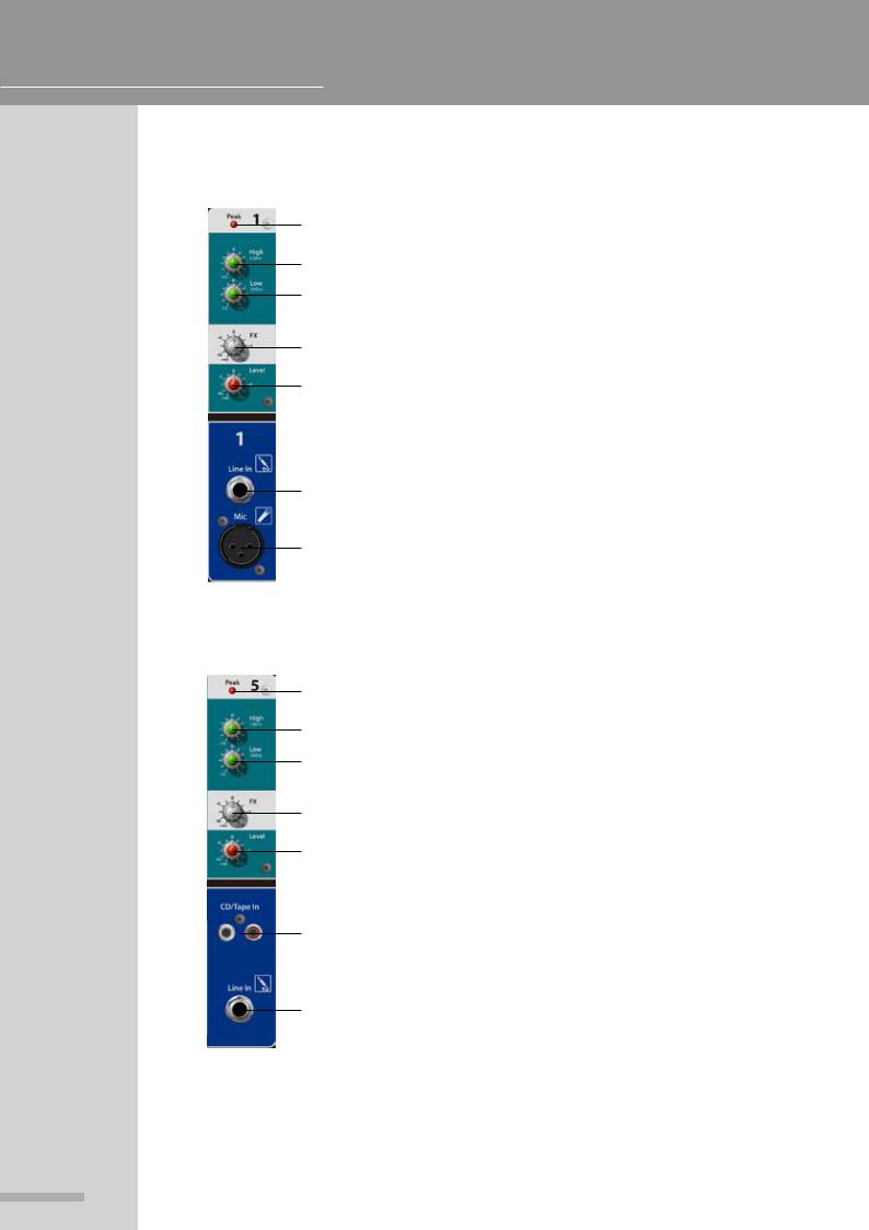
PMX 500 CHANNELS 1-4
1.Peak LED - Illuminates when the channel is clipping
2.High - High frequency shelving EQ, centered around 12kHz
3.Low - Low frequency shelving EQ, centered around 100Hz
4.FX Send - Sends signal to the built-in FX processor
5.Level - Controls the overall volume of the channel
6.Line in - Balanced / unbalanced ¼” TRS input for line level sources
7.Mic - Balanced XLR microphone input with switchable +48v phantom powering (Global Phantom power switch on rear of PMX unit)
1
2
3
4
5
6
7
PMX 500 CHANNEL 5
1.Peak LED - Illuminates when the channel is clipping
2.High - High frequency shelving EQ, centered around 12kHz
3.Low - Low frequency shelving EQ, centered around 100Hz
4.FX Send - Sends signal to the built-in FX processor
5.Level - Controls the overall volume of the channel
6.CD/Tape In - Dual phono inputs for connection of consumer level stereo sources, the input will be summed to mono
7.Line in - Balanced / unbalanced ¼” TRS input for line level sources
PMX Powered Mixer
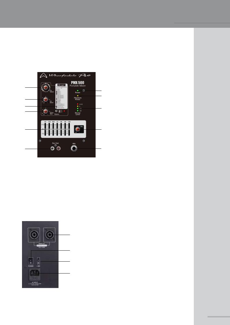
PMX 500 MASTER SECTION
1
4
6
7
8
9
1.FX Select - Selects the effect type that will be used
2.Power LED - Indicates AC supply
23. Phantom Power LED - Indicates +48v
3phantom powering is supplied to all of the XLR inputs. Please check that all
5connected microphones can withstand +48v power input
4.FX Send - Allows for master adjustment
of the FX send buss
105. Master Level LED’s - 4 segment LED metering for the master buss, if the limit LED illuminates constantly lower the master level to avoid damage to
11your loudspeakers
6.Bypass - Used to switch the internal FX processor on or off
7.FX to Mix - Controls the output level of the internal FX processor to the master buss
8.7-band EQ - Master section EQ to fine tune the overall sound
9.Rec Out - Line level output using phono connectors, provides connection to recording devices
10.Mix Level - Controls the main master volume
11.Mix output - Balanced / unbalanced ¼” TRS master output
PMX 500 REAR PANEL
1.Speakon™ outputs - Parallel outputs for connection to your loudspeakers
1PLEASE MAKE SURE THAT THE TOTAL IMPEDANCE OF THE LOAD IS NOT LESS THAN 4 OHMS.
22. Power Switch - Turns the unit on or off, ensure that AC
is supplied and that the levels have been turned down
3to protect your speakers
3.Phantom Power switch - Activates the +48v phantom
4powering for the 4 XLR inputs
4.IEC receptacle - Allows input of the supplied IEC lead for AC supply
 Loading...