


West Penn SC30030, SC30040, SC30050, SC30060, SC10120 Product Guide
...
Product Guide
IP CCTV
Networking Cabling, Accessories & Active Equipment
www.westpennwire.com

IP Video Systems
IP surveillance systems are relatively new to the market. In a typical IP-based video surveillance system, network (IP) cameras are connected directly to the Local Area Network (LAN) and transport digital video across the IP network via UTP cabling and switches, recording video to any PC or server on the network. Since the cameras are IP addressable, they are able to be accessed from anywhere in
the world, provided the user has the sufficient network access and security privileges.
Benefits of Using Fiber Optics
in Video Security and Surveillance
In the ever-increasing reach of today’s video security and surveillance systems, many security professionals are finding that the quality, bandwidth and distance needed to perform even the most basic surveillance is beyond the reach of coaxial and UTP cabling. In fact, even though IP-based video security systems are gaining popularity, they face a serious distance limitation of 100 meters (328ft) or less over UTP cabling infrastructure. This poses an insurmountable hurdle when trying to monitor the many outreach locations of a typical surveillance installation.
While fairing slightly better in copper distance limitations, most analog-based CCTV systems prove effective and economical only if the coaxial cabling runs are held to less than 750ft (228m). Utilizing coax beyond that distance, however, poses a number of problems, some of which are not immediately obvious. For instance, let’s say your monitor is located 1,000ft (304m) from the camera. In that scenario, without any active signal conditioning, approximately
37 percent of the high frequency information will be lost in transmission, providing a seriously degraded image. In fact, since you cannot see information that is not there, you may not even realize that information has been deleted.
To accommodate lengths greater than 750ft (228m) on a coax infrastructure, you must make certain that some provision has been made to guarantee the video signal’s transmission strength such as the use of signal amplification, ground fault correction and surge protection. Installing these items will inevitably increase the cost of the system considerably, making alternative cabling methods more attractive.
In fact, the use of fiber optic cable will allow for cable runs of over 1500m (5,000ft) on multimode and distances of over 10km (6.2 miles) on single-mode cable. In addition to distance extension, fiber optics also presents a number of other unique benefits not present in either coax or UTP cabling:
•Smaller size and better tensile strength, making it easier to install when pulling through conduit or in overhead cable trays
•High degree of security as fiber is inherently difficult to tap into or interfere with
•Immunity to electrical interference such as:
o Electromagnetic interference (EMI) o Radio frequency interference (RFI)
o High voltages found in fluorescent lights, card access door strikes and outdoor lighting systems
o Induced voltages (ground loops), which cause picture distortion and audio interference
•Higher bandwidth
•Improved reliability and overall transmission performance
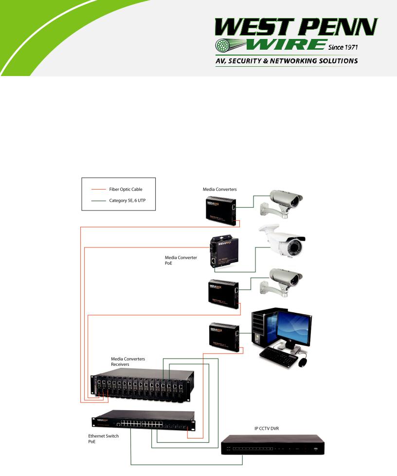
Local area networks (LANs) very commonly deploy fiber optics as the network backbone between buildings or in vertical risers of multistory buildings. Utilizing this infrastructure already in place would be an attractive transmission alternative to risking the distance and quality issues common to coax and UTP video systems. Accessing this fiber optic cabling can be a challenge for most video security professionals, as the majority of new cameras and monitors on the market today are unavailable with fiber optic ports on them. In addition, most existing video security and surveillance systems were designed and installed with coax or UTP cabling. To improve the quality, bandwidth and distance of these existing systems by transporting the video on fiber optic cabling, a method is required to convert the electrical video signal over to an optical format.
IP Video Conversion
•Ethernet Media Converters – powered devices that convert an IPbased video signal on UTP over to a fiber optic medium
•Power over Ethernet (PoE) Media Converters – powered devices that convert an IP-based video signal UTP over to a fiber optic medium, as well as inject the power onto the UTP necessary to power remote IP cameras
Media converters come in a variety of form factors and sizes ranging from miniature, standalone devices that attach directly to a camera to managed, chassis-based devices allowing for full SNMP monitoring and management of the media converters.
In addition to providing a means for transparently connecting one type of media to another, media conversion can provide a cost-effec- tive method for integrating a hybrid video security and surveillance system into one, seamless and manageable entity. Imagine the cost savings that can be realized by utilizing an existing, analog-based CCTV infrastructure, while implementing the latest technology of IP-based cameras for specialized video capture, storage or analysis, as well as additional surveillance locations.
Access Video Any Time, Any Place
With IP-based systems, video feeds are encoded into Motion JPEG or MPEG-4/H.264 formats and stored as a digital image on a computer disk array. This provides the ability to access the video, by way of the networked digital video recorder, through the IP network at any time, from any place. These digital images do not degrade in quality from duplication like analog recordings on magnetic tape. They can be replicated and posted on web servers, distributed to law enforcement as E-mail attachments, and sent to news outlets. When analog-based systems were the norm, loss prevention/investigations staff had to visit the location of the incident to view the video on a tape or
DVD, which would need to be shipped by overnight courier. These inefficiencies no longer exist with IP-based systems and WAN connectivity to the physical location.
www.westpennwire.com |
2 |
|
|

TABLE OF CONTENTS |
|
IP CCTV Design.................................................................................................................................................... |
1 |
IP Cabling Network Cables.............................................................................................................................. |
2 |
Category Cable Types........................................................................................................................................ |
3 |
Connector Types RJ45....................................................................................................................................... |
4-5 |
Wall Plate Types................................................................................................................................................... |
6 |
Cable Assemblies................................................................................................................................................ |
7 |
Patch Panels.......................................................................................................................................................... |
8 |
Fiber Optic Cable Types.................................................................................................................................... |
9 |
Fiber Optic Kits/Connectors............................................................................................................................ |
10 |
Fiber Optic Assemblies..................................................................................................................................... |
11 |
Fiber Optic Long-Length Assemblies.......................................................................................................... |
12 |
Fiber Optic Panels/Adapter Plates................................................................................................................ |
13 |
Ethernet Switch................................................................................................................................................... |
14 |
www.westpennwire.com |
3 |
|
|
IP CCTV Design
In an IP-CCTV design, the cable is an important link from equipment to camera. Category cables such as Category 5E and Category 6 UTP are essential to this design. The cabling distance of category cables is up to 330ft. For distances beyond 330ft, fiber optic cables are needed with media converters. Fiber media converters support many different data communication protocols including Ethernet, Fast Ethernet overtwisted pair, multimode and single-mode fiber optics. Media converter types range from small standalone devices and PC card converters to high port-density chassis systems that offer many advanced features for network management.
www.westpennwire.com |
4 |
|
|
IP Cabling
Network cabling is used to describe cabling that links network devices in user work areas (WAs) to network equipment located in the telecommunications room (TR). This cabling generally extends horizontally along floors, walls and ceilings.
Distance: 90m link - Link is the bulk cable run without assemblies or patch cables. 100m channel - Channel is the entire run of cable, including assemblies and patch cables.
Topology: Star configuration - from hub to desktop.
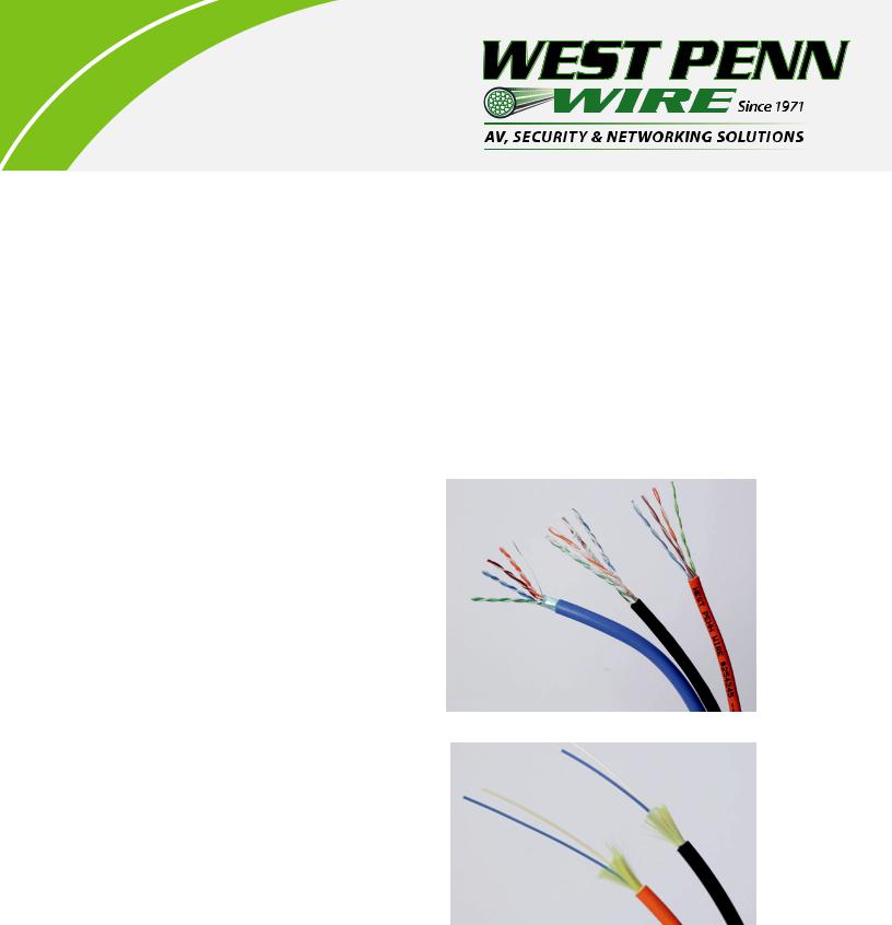
Cabling Media Types
•4-pair 100 ohm Impedance UTP (Unshielded Twisted Pair) or F/UTP (Foil over UTP - Shielded).
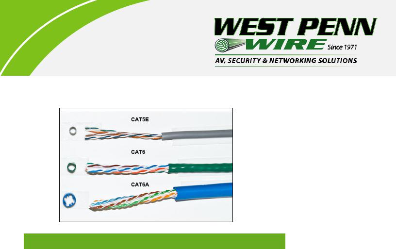
•Category 5E: TIA/EIA-568.B.2
•4-Pair 24AWG
•Voice or Data - Data: 10/100BaseT Ethernet
•UTP or F/UTP Design
•Category 6: TIA/EIA-568-B.2-1
•4-Pair 24 or 23AWG
•Data: 100/1000BaseT Ethernet
•UTP or F/UTP Design
•Category 6A: TIA/EIA-568-B.2-10
•Augmented Cat6
•4-Pair 23AWG
•Data: 100/1000/10000BaseT Ethernet
•UTP or F/UTP Design
•Category 7:
•4-Pair 23 or 22AWG
•Data: 10GBaseT Ethernet
•S/FTP Design - Shielded over Shielded Pair
•Optical Fiber OM1, OM2, OM3, OM4 Design
•OM1: 62.5/125µm Fiber Shorter Runs
•OM2: 50/125µm
•OM3: 50/125µm Laser Optimized 10G Network
•OM4: 50/125µm 40G Network
www.westpennwire.com |
5 |
|
|
West Penn Wire Bulk Cables
Environment |
Category 5E UTP |
Category 6 UTP |
Category 6A UTP |
|
|
|
|
Non-Plenum |
4245 |
4246 |
4246A |
|
|
|
|
Plenum |
254245 |
254246 |
254246A |
|
|
|
|
Indoor/Outdoor |
4245IO |
4246IO |
|
Outside Plant |
4245OSP |
4246OSP |
|
|
|
|
|
Armored |
M57562 |
|
|
|
|
|
|
Mechanical Characteristics
Pull Tension: |
|
Cat5E |
25lbf |
Cat6 |
25lbf |
Cat6A |
35lbs |
Bend Radius: |
|
Category Cable |
4 x cable O.D. |
www.westpennwire.com |
6 |
|
|
 Loading...