

Western Digital H4102-J User Manual

User Guide
Ultrastar Data102
Regulatory Model: H4102-J
December 2020
Rev. 1.18
1ET1094

User Guide Table of Contents
Table of Contents
Revision History.................................................................................................................................... vi
Notices....................................................................................................................................................x
Points of Contact.................................................................................................................................. xi
Product Label Information..............................................................................................................xi
Chapter 1. Overview.........................................................................................................1
Ultrastar Data102 Description..............................................................................................................2
System Architecture Overview........................................................................................................... 2
System Level Block Diagram...............................................................................................................3
Environmental Specifications...............................................................................................................3
Electrical Specifications....................................................................................................................... 4
Mechanical Specifications....................................................................................................................4
Performance Specifications................................................................................................................. 5
Ultrastar Data102 Layout......................................................................................................................5
List of Customer Replaceable Units (CRUs).......................................................................................7
Supported Operating Systems........................................................................................................... 8
LEDs.......................................................................................................................................................9
Front and Rear IO LEDs................................................................................................................9
IOM LEDs.......................................................................................................................................11
IOM Fan LED................................................................................................................................. 11
PSU LED........................................................................................................................................12
Rear Fan LED................................................................................................................................13
Drive Assembly LED.................................................................................................................... 14
Ultrastar Data102 Rack Requirements............................................................................................... 15
Compatible Rack Hardware Configuration................................................................................17
Power Requirements.......................................................................................................................... 19
ESD....................................................................................................................................................... 19
Enclosure Cooling...............................................................................................................................19
i

User Guide Table of Contents
SAS Cabling........................................................................................................................................20
Supported SKUs................................................................................................................................. 22
List of Compatible Drives..................................................................................................................22
Chapter 2. Components................................................................................................34
Chassis.................................................................................................................................................35
Chassis Specifications................................................................................................................ 35
Chassis Layout.............................................................................................................................36
IOM...................................................................................................................................................... 38
IOM Specifications...................................................................................................................... 38
IOM Layout.................................................................................................................................. 39
IOM Blank.....................................................................................................................................39
PSU...................................................................................................................................................... 40
PSU Specifications...................................................................................................................... 40
PSU Layout................................................................................................................................... 41
Rear Fan.............................................................................................................................................. 42
Rear Fan Specifications.............................................................................................................. 42
Rear Fan Layout.......................................................................................................................... 43
IOM Fan............................................................................................................................................... 44
IOM Fan Specifications............................................................................................................... 44
IOM Fan Layout........................................................................................................................... 45
Rails......................................................................................................................................................46
Rails Specifications..................................................................................................................... 46
Rails Layout..................................................................................................................................47
Rear Cover Alignment Bracket.................................................................................................. 48
CMA..................................................................................................................................................... 49
CMA Specifications..................................................................................................................... 49
CMA Layout.................................................................................................................................50
CMA Cable Tray...........................................................................................................................51
CMA Lite............................................................................................................................................. 52
ii

User Guide Table of Contents
CMA Lite Specifications............................................................................................................. 52
CMA Lite Layout..........................................................................................................................53
3.5in HDD Assembly.......................................................................................................................... 54
3.5in HDD Assembly Specifications.......................................................................................... 54
3.5in HDD Assembly Layout...................................................................................................... 55
3.5in Drive Blank......................................................................................................................... 56
2.5in SSD Assembly............................................................................................................................57
Operating the 2.5" Drive Carrier............................................................................................... 57
Chapter 3. Support........................................................................................................60
Part Replacement Service Window.................................................................................................. 61
IOM Replacement............................................................................................................................... 61
PSU Replacement...............................................................................................................................64
Rear Fan Replacement.......................................................................................................................68
IOM Fan Replacement........................................................................................................................ 71
3.5in HDD Assembly Replacement................................................................................................... 73
CMA Replacement..............................................................................................................................77
Rails Replacement............................................................................................................................ 100
Chassis Replacement........................................................................................................................132
Special Considerations for Cable Routing.......................................................................................171
Cabling for CMA Standard and CMA Lite....................................................................................... 173
Before You Begin....................................................................................................................... 173
Cabling CMA Standard..............................................................................................................174
Cable Configuration for CMA Lite............................................................................................175
Chapter 4. Management.............................................................................................. 177
Management Overview.................................................................................................................... 178
Firmware Features Overview.......................................................................................................... 178
Firmware Upgrade............................................................................................................................ 179
Downloading Firmware from the Support Portal....................................................................179
iii

User Guide Table of Contents
Linux Upgrade Preparation........................................................................................................181
Linux Upgrade to New Firmware.............................................................................................183
Non-Automatic Firmware Activation in Linux.......................................................................... 185
Windows Firmware Upgrade Preparation...............................................................................187
Windows Upgrade to New Firmware..................................................................................... 188
Non-Automatic Firmware Activation in Windows................................................................... 191
OOBM Management Overview........................................................................................................ 194
Configuring OOBM Network Settings Using SES....................................................................194
Upgrading Firmware with OOBM.............................................................................................196
SES Page 02...................................................................................................................................... 198
Zoning................................................................................................................................................198
Before Zoning............................................................................................................................ 198
Predefined Zoning Configurations........................................................................................... 198
sg_senddiag Command...........................................................................................................205
Enabling Zoning using Linux....................................................................................................205
Disabling Zoning using Linux...................................................................................................209
Enabling Zoning using Windows.............................................................................................212
Disabling Zoning using Windows............................................................................................215
File-Based Zoning......................................................................................................................219
Subenclosure Nickname.................................................................................................................. 229
Setting the Subenclosure Nickname....................................................................................... 229
Partially Populated Enclosures.........................................................................................................231
Partial Population Configurations............................................................................................. 231
Installing Drives......................................................................................................................... 234
Daisy Chaining.................................................................................................................................. 238
Daisy Chaining Configurations.................................................................................................238
One Host Cable Configurations.............................................................................................. 239
Two Host Cable Configurations.............................................................................................. 245
iv

User Guide Table of Contents
Cabling for Daisy Chaining...................................................................................................... 250
Chapter 5. Safety.........................................................................................................257
Safety Warnings and Cautions........................................................................................................258
Electrostatic Discharge....................................................................................................................258
Optimizing Location.........................................................................................................................258
Power Connections..........................................................................................................................259
Power Cords.....................................................................................................................................259
Rackmountable Systems..................................................................................................................259
Safety and Service........................................................................................................................... 260
Chapter 6. Disclaimers.................................................................................................261
Restricted Access Location.............................................................................................................262
Safety Compliance........................................................................................................................... 262
Electromagnetic Compatibility (EMC) Class A Compliance......................................................... 262
Country Certifications...................................................................................................................... 263
Chapter 7. Regulatory Statements............................................................................264
Europe (CE Declaration of Conformity)..........................................................................................265
FCC Class A Notice......................................................................................................................... 265
ICES-003 Class A Notice—Avis NMB-003, Classe A..................................................................... 265
Japanese Compliance Statement, Class A ITE.............................................................................. 265
Taiwan Warning Label Statement, Class A ITE.............................................................................. 266
v

User Guide Revision History
Revision History
Date Revision Comment
November 2017 1.0 Initial release
November 2017 1.1
December 2017 1.2
January 2018 1.2.1 Updated the product name
January 2018 1.3
• The crossbar on the CMA was changed. See CMA (page 49).
• Removed Lowline power specs from Power Requirements (page
19).
• Changed required rack depth, see Mechanical Specifications (page
4).
• Changed typical power consumption, see Electrical Specifications
(page 4).
• Updated LED Flash Patterns, see LEDs (page 9).
• Added active cable support
• Added firmware upgrade section. See Firmware Upgrade (page
179).
• Updated the Non-Op altitude specification. See Environmental
Specifications (page 3).
• Updated information on the 2.5" drive carrier option. See 2.5in SSD
Assembly (page 57).
• Added torque requirements for all screws used in the enclosure.
• Updated the IOM replacement section to account for the possibility
of a firmware mismatch. See IOM Replacement (page 61).
• Updated the drive assembly installation instructions to clarify
the orientation of the drive assemblies. 3.5in HDD Assembly
Replacement (page 73).
April 2018 1.4
May 2018 1.5 Added the Part Replacement Service Window. See: Part Replacement
June 2018 1.6
• Updated Compatible Drives List. See List of Compatible Drives
(page 22).
• Updated the Rack Requirements. See Ultrastar Data102 Rack
Requirements (page 15).
• Updated the Firmware Upgrades. See: Firmware Upgrade (page
179)
Service Window (page 61)
• Updated Compatible Drives List. See List of Compatible Drives
(page 22)
• Updated the Firmware Upgrade section. See Firmware Upgrade
(page 179)
vi

User Guide Revision History
Date Revision Comment
• Updated the Firmware Download section. See Downloading
Firmware from the Support Portal (page 179)
• Updated the System Architecture Overview section. See System
Architecture Overview (page 2)
• Updated the Daisy Chaining section. See Daisy Chaining (page
238)
• Added the Rear Cover Alignment Bracket Description. See Rear
Cover Alignment Bracket (page 48)
November 2018 1.7
May 2019 1.8
May 2019 1.9
June 2019 1.10
• Updated the images in the Daisy Chaining section. See Daisy
Chaining (page 238)
• Updated List of CRUs. See List of Customer Replaceable Units
(CRUs) (page 7)
• Updated Compatible Drives List. See List of Compatible Drives
(page 22)
• Updated the Host Connectivity section. See: SAS Cabling (page
20)
• Changed senddiag commands from images to codeblocks. See
sg_senddiag Command (page 205).
• Updated daisy-chaining tables to match diagrams. See Two Host
Cable Configurations (page 245).
• Corrected OOBM zoning configuration instructions. See Predefined
Zoning Configurations (page 198).
• Added Configuring OOBM Network Settings Using SES (page
194).
• Corrected explanation of SATA configuration in Firmware Upgrade
(page 179) section.
• Updated the Host Connectivity section. See: SAS Cabling (page
20)
• Added Windows syntax examples and reorganized the Upgrading
Firmware with OOBM section
June 2019 1.11 Updated the Host Connectivity section. See: SAS Cabling (page 20)
July 2019 1.12
Moved the following topics to the Ultrastar Data102 Description (page
2) section:
• Ultrastar Data102 Rack Requirements (page 15)
• Power Requirements (page 19)
• ESD (page 19)
• Enclosure Cooling (page 19)
• SAS Cabling (page 20)
vii

User Guide Revision History
Date Revision Comment
Moved the Supported Operating Systems (page 8) topic to the
Management (page 177) section.
Corrected LED identification tables for IOMs, PSUs, and drives in the
LEDs (page 9) section.
Updated servicing image to correct length values and rail servicing
extension in Ultrastar Data102 Rack Requirements (page 15) section.
Updated the following for CMA Lite:
• Added CMA Lite Component Overview (page 52) section,
including description, specs, and layout.
• Updated CMA Replacement (page 77) section to combine CMA
Standard and CMA Lite content where applicable.
• Updated Maximum HD Mini-SAS Configuration (page 175) section.
Added a note about OOBM ports configured for DHCP by default to the
OOBM Management Overview (page 194) section.
September 2019 1.13
November 2019 1.14
April 2020 1.15
• Replaced references to He12 drives with Ultrastrar DC HC520 in List
of Compatible Drives (page 22)
• Changed device references from OS-specific (/dev/sgX for Linux
and SCSIX:X,X,X for Windows) to generic (<dev>) throughout.
• Updated table for Approved SAS Cables in SAS Cabling (page
20)
• Added Subenclosure Nickname (page 229) section
• Updated Supported Operating Systems (page 8)
• Updated images of captive chassis-cover screws throughout
• Updated table for Approved SAS Cables in SAS Cabling (page
20)
• Updated the Daisy Chaining configurations in Daisy Chaining (page
238)
• Added note about using non-automatic firmware activation for RAID
adpaters in Firmware Upgrade (page 179)
• Added note about performing zoning offline in Zoning (page 198)
• Added note and step for configuring zoning on an IOM after
replacement in IOM Replacement (page 61)
• Added RHEL 8.0 to Supported Operating Systems (page 8)
• Added note about LED behavior during proper drive insertion in
Drive Assembly LED (page 14)
• Added note about minimum time between removing and
reapplying power in Power Connections (page 259)
August 2020 1.16
• Updated Supported Operating Systems (page 8)
• Updated SAS Cabling (page 20)
viii

User Guide Revision History
Date Revision Comment
• Updated List of Compatible Drives (page 22)
• Added File-Based Zoning (page 219) section
• Updated note in IOM Replacement (page 61) about standard vs.
file-based zoning configuration after IOM replacement
October 2020 1.17
December 2020 1.18
• Fixed typo in Rails Layout (page 47)
• Updated text and color-coded images in Predefined Zoning
Configurations (page 198)
• Updated images in LEDs (page 9) and Components (page
34)
• Added note about not unzipping tar.gz file prior to firmware
upgrade in Downloading Firmware from the Support Portal
(page 179), Linux Upgrade to New Firmware (page 183), Non-
Automatic Firmware Activation in Linux (page 185), Windows
Upgrade to New Firmware (page 188), and Non-Automatic
Firmware Activation in Windows (page 191)
• Added Ubuntu 20.04 to Supported Operating Systems (page 8)
• Updated table of approved SAS cables in SAS Cabling (page 20)
• Updated FW activation step in Upgrading Firmware with OOBM
(page 196)
• Added UK Import Representation Contact
• Removed Formerica cables from SAS Cabling (page 20)
ix

User Guide Notices
Notices
Western Digital Technologies, Inc. or its affiliates' (collectively “Western Digital”) general policy does not
recommend the use of its products in life support applications wherein a failure or malfunction of the product
may directly threaten life or injury. Per Western Digital Terms and Conditions of Sale, the user of Western
Digital products in life support applications assumes all risk of such use and indemnifies Western Digital
against all damages.
This document is for information use only and is subject to change without prior notice. Western Digital
assumes no responsibility for any errors that may appear in this document, nor for incidental or consequential
damages resulting from the furnishing, performance or use of this material.
Absent a written agreement signed by Western Digital or its authorized representative to the contrary,
Western Digital explicitly disclaims any express and implied warranties and indemnities of any kind that may,
or could, be associated with this document and related material, and any user of this document or related
material agrees to such disclaimer as a precondition to receipt and usage hereof.
Each user of this document or any product referred to herein expressly waives all guaranties and warranties
of any kind associated with this document any related materials or such product, whether expressed or
implied, including without limitation, any implied warranty of merchantability or fitness for a particular
purpose or non-infringement. Each user of this document or any product referred to herein also expressly
agrees Western Digital shall not be liable for any incidental, punitive, indirect, special, or consequential
damages, including without limitation physical injury or death, property damage, lost data, loss of profits or
costs of procurement of substitute goods, technology, or services, arising out of or related to this document,
any related materials or any product referred to herein, regardless of whether such damages are based on
tort, warranty, contract, or any other legal theory, even if advised of the possibility of such damages.
This document and its contents, including diagrams, schematics, methodology, work product, and
intellectual property rights described in, associated with, or implied by this document, are the sole and
exclusive property of Western Digital. No intellectual property license, express or implied, is granted by
Western Digital associated with the document recipient's receipt, access and/or use of this document or the
products referred to herein; Western Digital retains all rights hereto.
Western Digital, the Western Digital logo, and Ultrastar are registered trademarks or trademarks of Western
Digital Corporation or its affiliates in the US and/or other countries. Linux® is the registered trademark of
Linus Torvalds in the U.S. and other countries. All other marks are the property of their respective owners.
Product specifications subject to change without notice. Pictures shown may vary from actual products. Not
all products are available in all regions of the world.
Western Digital
5601 Great Oaks Parkway
San Jose, CA 95119
© 2020 Western Digital Corporation or its affiliates. All Rights Reserved.
x

User Guide Points of Contact
Points of Contact
For further assistance with a Western Digital product, contact Western Digital Datacenter Platforms technical
support. Please be prepared to provide the following information: part number (P/N), serial number (S/N),
product name and/or model number, and a brief description of the issue.
Email:
support@wdc.com
Website:
https://portal.wdc.com/Support/s/
UK Import Representation Contact
Western Digital UK Limited Hamilton House, Regent Park, Kingston Road Leatherhead, Surrey KT22 7PL, GB,
United Kingdom
Telephone: +44 1372 366000
1.1 Product Label Information
The following product information is required for technical support requests:
• Part Number (P/N)
• Serial Number (S/N)
• Product Name and/or Model Number (MODEL)
This information may be found on the product label, which is affixed to an exterior, non-removable surface of
the chassis. The following is an example label with the applicable information fields highlighted:
xi

Western Digital
Overview
This section provides a high level overview of the features of the
Ultrastar Data102 .
In This Chapter:
- System Architecture Overview.....................2
- System Level Block Diagram.........................2
- Environmental Specifications........................3
- Electrical Specifications................................ 3
- Mechanical Specifications............................. 4
- Performance Specifications...........................4
- Ultrastar Data102 Layout............................... 5
- List of Customer Replaceable Units
(CRUs)............................................................... 5
- Supported Operating Systems......................7
- LEDs................................................................. 8
- Ultrastar Data102 Rack Requirements..........9
- Power Requirements.................................... 15
- ESD..................................................................19
- Enclosure Cooling.........................................19
- SAS Cabling................................................... 19
- Supported SKUs........................................... 20
- List of Compatible Drives............................22
1
User Guide
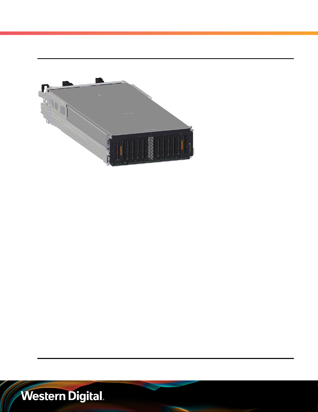
1.1 Ultrastar Data102 Description
Figure 2: Ultrastar Data102
1. Overview
1.1 Ultrastar Data102 Description
The Ultrastar Data102 is a 4U form factor, high availability, high density, rack-mounted storage enclosure
that is capable of hosting up to 102 SAS or SATA drives. The maximum data storage capacity of the Ultrastar
Data102 is 1.428 PB using 14TB HGST Ultrastar® HC530 drives . (For a full list of compatible drives and total
storage capacities, see the List of Compatible Drives (page 22).) The enclosure runs on an input voltage
of 200 - 240 VAC and consumes ~1300W of power under typical conditions. It requires a maximum of
~1600W at full load.
It is designed to fit within a 4U rack space and requires 1181-1197 mm (46.5in. - 47.13in.) of usable rack space,
frame to frame. A fully loaded system will add 118.8 kg / 262 lbs. of static load when fully loaded with drives.
• 4U Storage Enclosure
• Supports up to 102 Drives
• Can support 3.5” drives and 2.5” SSD drives (2.5" requires an adapter) in the 102 available drive bays.
• Up to 12W per drive slot for the 102 data storage drives (Cannot exceed 85A on the 5V rail)
• House and control four (4) N+1 redundant 80mm rear fans
• House and control a dual rotor 40mm internal IOM Fan
• Controlled by two (2) redundant I/O Modules
• Powered by two (2) redundant 1600W PSUs
• Supports High Line (220-240 VAC) Input Power
• Full high availability with independent dual paths to all HDDs
• Toolless replacement of all Customer Replaceable Units (CRUs)
• Fits within a standard EIA-310 rack including all necessary cable management (see Compatible Rack
Hardware Configuration (page 17))
• Supports up to 3m passive SAS cables (limited to 3m or less) or active cables (any length) (see SAS
Cabling (page 20))
1
1.2 System Architecture Overview
1. SATA based models will only include 1 IOM
2
User Guide
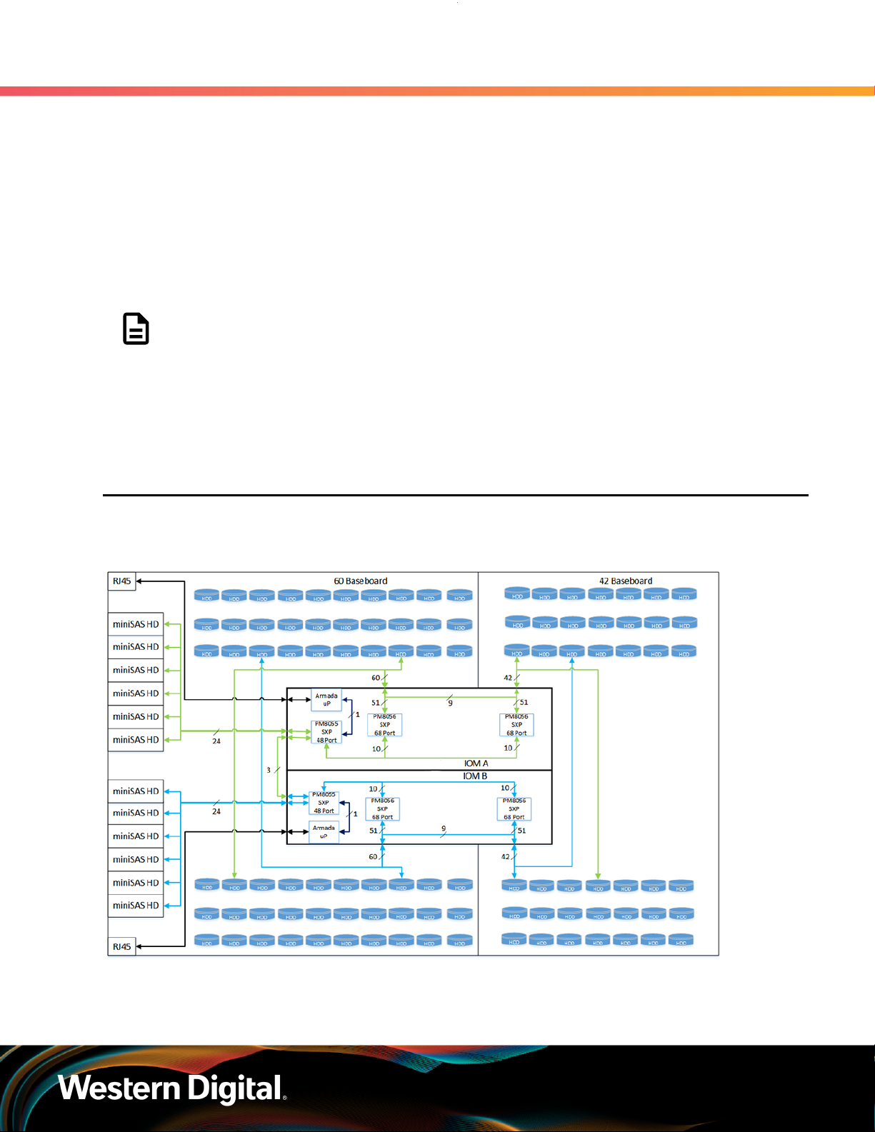
The Ultrastar Data102 IOM uses a cascaded expander design to allow for connection to all 102 drives.
A 48-port primary expander connects with the six host ports, has a x3 link to the other IOM for IOM-IOM
communication and syncing, and also has a x10 SAS link to each secondary expander. Each secondary
expander then connects with fifty-one (51) drives.
The out-of-band management microprocessor provides an Ethernet connection using a Redfish/RESTful
API to access the various enclosure services. All the SES enclosure information can be obtained through the
out-of-band management port. Major use cases for this feature include obtaining storage subsystem health
information, locating enclosure components using the IDENT LEDs, and updating firmware.
The system FPGAs control and report the states of the system fans, enclosure LEDs, connector LEDs, drive
LEDs, and T10 drive power disable signals on the 102 data storage drives.
The I2C architecture is designed to support only one single master on any given bus. The primary expander
will be the master on each I2C bus. There are eight I2C buses used in the Ultrastar Data102 enclosure.
The number of devices on each bus are balanced to allow communication to peripheral devices and not
overload any one bus. The devices connected on the I2C buses include the enclosure VPDs, temp sensors,
baseboard FPGAs, and SAS connectors among others.
1. Overview
1.3 System Level Block Diagram
Note: To use T10 power disable, the drives installed must also support this feature.
1.3 System Level Block Diagram
The following image shows the system block diagram for the Ultrastar Data102 .
Figure 3: System Block Diagram
3
User Guide
1.4 Environmental Specifications
Table 1: Environmental Specification
Specification Non-Operational Operational
Temperature -40°C to 70°C 5°C to 35°C
Temperature Gradient 30°C per hour max 20°C per hour max
Temperature De-rating 1°C per 300m above 3000m 1°C per 300m above 900m
Relative Humidity 8-90% Non-Condensing 8-90% Non-Condensing
Relative Humidity Gradient 30% per hour maximum 30% per hour maximum
1. Overview
1.4 Environmental Specifications
Altitude -300m to 12,000m /
-984 ft. to 39,370 ft
1.5 Electrical Specifications
Table 2: Electrical Specifications
Specification Value
Max Power Consumption ~1600W
Typical Power Consumption
Input Voltage 200 - 240 VAC
PSU Connector Type C14
PSU Efficiency 80 PLUS Platinum
Inrush Current Maximum (per
Caution: The Ultrastar Data102 can only be plugged into high line (200 - 240 VAC) power. If
the unit is plugged into low line (110-127 VAC), the PSU will report a "Critical" state when status
pages are queried using SES. In this case, the enclosure will power up, but the drives will not.
The enclosure will remain in low-power mode.
2
AC line inrush current shall not exceed 40A peak, for up to
PSU)
should be no more than the specified maximum input current.
-300m to 3048m /
-984 ft. to 10,000 ft.
~1300W
one-quarter of the AC cycle after which, the input current
1.6 Mechanical Specifications
2. Max and typical power consumption values represent the output power to the system. Input power will vary depending
on the PSU efficiency and load sharing between PSUs.
4

User Guide
Table 3: Mechanical Specifications
1.7 Performance Specifications
Specification Non-Operational Operational
Shock 10G, 0 - peak,11ms half sine;
3 positive and 3 negative
pulses in each axis Shock
5G, 0 - peak, 11ms half sine; 3 positive
and 3 negative pulses in each axis-
minimum 6 seconds between shocks
to allow for write/read recovery
1. Overview
Vibration 0.75G, 0 - peak swept sine;
5 -500Hz; 1 complete sweep
@ 1/2 octave per minute
Weight 118.8 kg / 262 lbs.
Enclosure Dimensions W: 447mm x L: 1048.5 mm x H: 175mm / W: 17.6in. x L: 41.28in. x H: 6.89in.
CMA
Required Rack Width 450mm with (17.72in.) with 465mm (18.31in.) ± 1.5mm
nominal hole spacing. See EIA-310 Rack Standard
Required Rack Depth 1181-1197 mm (46.5in. - 47.13in.) of usable rack space, frame to frame
Rack Units (U) 4U
Vertical Rack Rail
Spacing
1.7 Performance Specifications
Table 4: Performance Specifications
0.10G,0 - peak swept sine; 5
-500Hz; 1 complete sweep
@ 1/2octave per minute
CMA Standard: 1183mm / 46.57in.Length of Enclosure w/
CMA Lite: 1148mm / 45.19in.
812.8mm - 914.4mm / 32 in. - 36 in.
Specification Value
Number of Drive Slots 102
Data Transfer Rates 12GBps SAS / 6Gbps SATA
Max Raw Data Storage Capacity 1.428 PB using 14TB HGST Ultrastar® HC530 drives
SAS Ports 12 x Mini-SAS HD (6 per IOM)
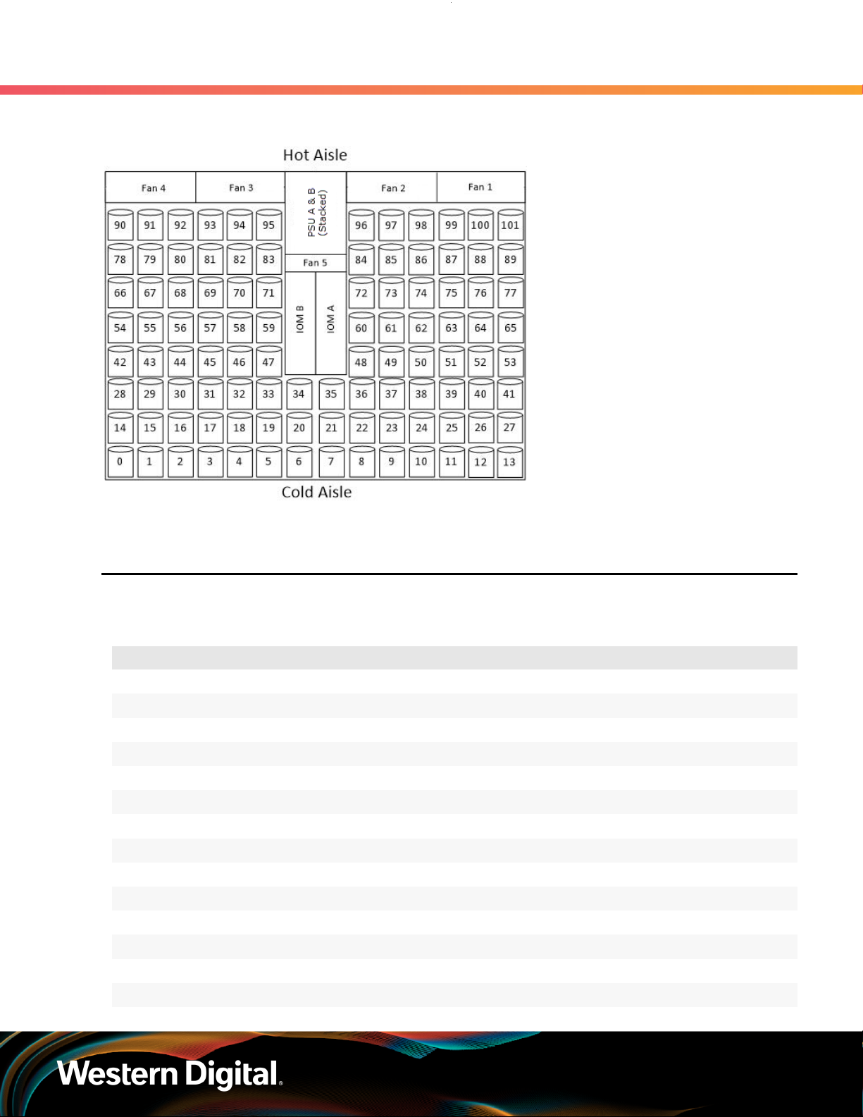
1.8 Ultrastar Data102 Layout
2 x 10/100/1G Ethernet
5
User Guide
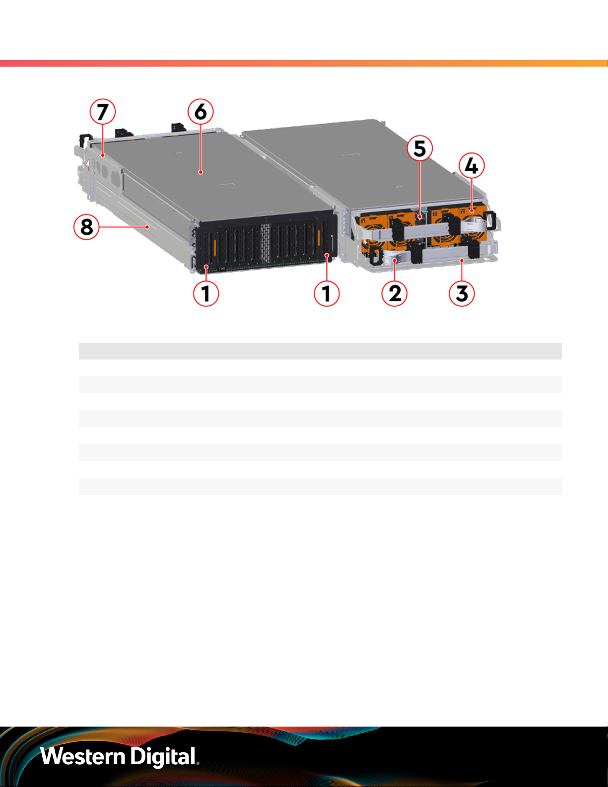
Figure 4: Front and Rear Product Layout
1. Overview
1.8 Ultrastar Data102 Layout
Table 5: Front and Rear Component Identification
Number Component
1 Enclosure Handles
2 CMAs
3 CMA Tray
4 Rear Fans
5 PSUs
6 Chassis Cover
7 Rear Cover Alignment Brackets
8 Rails
The following is an image of the layout of the major system components inside the Ultrastar Data102 .
6
User Guide
Figure 5: Component Layout
1. Overview
1.9 List of Customer Replaceable Units (CRUs)
1.9 List of Customer Replaceable Units (CRUs)
The following table lists the replaceable components and their part numbers.
Table 6: List of Replaceable Components
Component Part Number
Ultrastar Data102 Chassis with a single IOM and PSUs 1EX0440
Ultrastar Data102 Chassis with IOMs and PSUs 1EX0441
IOM 1EX2201
IOM Blank 1EX0431
PSU 1600W 1EX0434
Rear Fan 1EX0433
IOM Fan 1EX0432
Rails (CMA Standard) 1EX0435
Rails (CMA Lite) 1EX1601
Rear Cover Alignment Bracket 1EX2288
CMA Standard Arms 1EX0437
CMA Lite Kit (w/ rails, spacer brackets, and CMA) 1EX1825
CMA Lite Arm 1EX1834
CMA Lite Cable Tray 1EX1603
7

User Guide
Component Part Number
CMA Cable Tray 1EX1119
3.5 in. Drive Carrier, Qty=1 1EX0438
3.5 in. to 2.5 in. conversion Drive Carrier, Qty=1 1EX0439
3.5 in. Drive Blank, Qty=1 1EX0429
Power Cable for PDU, C13-C14, 18AWG, 3m, Qty=1 1EX1158
HD Mini-SAS to HD Mini-SAS, 3m, Qty=2 1EX1533
1.10 Supported Operating Systems
Table 7: Compatible Operating Systems
OS Support
Microsoft® Windows
1. Overview
1.10 Supported Operating Systems
2012 R2 x64 Server
2016 R1 x64 Server
CentOS/RedHat® Enterprise Linux (RHEL)
Ubuntu® Server
2019 R1 x64 Server
7.2 (x86_64) Kernel: 3.10.0-327
7.3 (x86_64) Kernel: 3.10.0-514
7.4 (x86_64) Kernel: 3.10.0-693
7.6 (x86_64) Kernel: 3.10.0-957
8.0 (x86_64) Kernel: 4.18.0-80
8.2 (x86_64) Kernel: 4.18.0-193
14.04 Kernel: 3.13
16.04 Kernel: 4.4
18.04 Kernel: 4.15
20.04
8.10 Kernel: 3.16Debian GNU/Linux
9.6 Kernel: 4.9
12 SP3SUSE® Linux Enterprise Server (SLES)
15 SP1
8
User Guide
1.11 LEDs
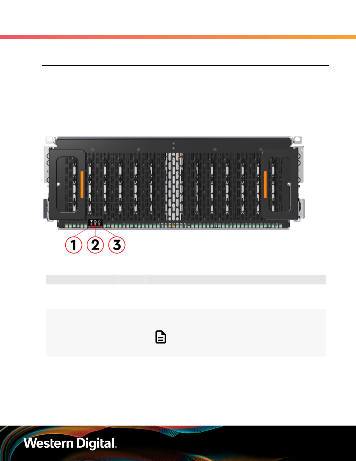
1.11.1 Front and Rear IO LEDs
The Ultrastar Data102 has a number of LEDs on the exterior of the enclosure that display various system
statuses. The three LEDs on the front mirror three on the rear, allowing the general status of the enclosure
to be determined from either side of the rack.
Figure 6: Front LEDs Location
1. Overview
1.11 LEDs
Table 8: Front LEDs Identification
Number LED Name Color Behavior
1 Identify Blue Blink @ 1 Hz (50% duty cycle) – Blinks only when Identification
has been activated. Will blink when any component is
identified.
2 Fault Amber Blink @ 1 Hz (50% duty cycle) – Enclosure has a fault
Off – Enclosure has no fault
Note: LEDs have a 50% duty cycle (On for 2
seconds, off for less than a second).
3 Power Green Solid – Powered On
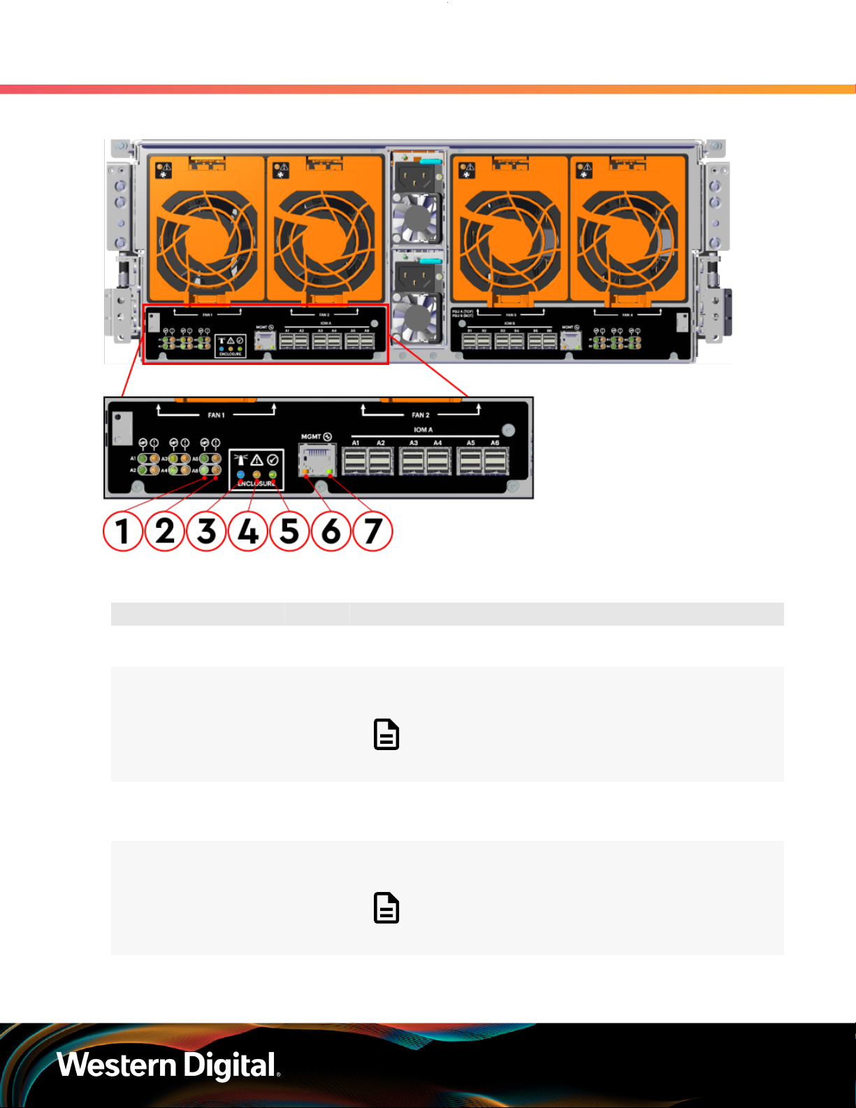
In addition to the three enclosure status LEDs, the rear provides LEDs for the Ethernet and SAS ports.
9
User Guide
Figure 7: Rear LEDs Location
1. Overview
1.11 LEDs
Table 9: Rear LEDs Identification
Number LED Name Color Behavior
1 SAS Link Status Green Solid – SAS cable connected
Off – SAS cable not connected
2 SAS Fault
Status
3 Identification Blue Blink @ 1 Hz (50% duty cycle) – Blinks only when Identification
4 Fault Amber Blink @ 1 Hz (50% duty cycle) – Enclosure has a fault
5 Power Green Solid – Powered On
Amber Blink @ 1 Hz (50% duty cycle) – SAS connection fault
Off – No SAS connection fault
Note: LEDs have a 50% duty cycle (On for 2
seconds, off for less than a second).
has been activated. Will blink when any component is
identified.
Off – Enclosure has no fault
Note: LEDs have a 50% duty cycle (On for 2
seconds, off for less than a second).
10
User Guide
Number LED Name Color Behavior
6 Ethernet
Connector
Speed
Green/
Amber
1. Overview
1.11 LEDs
Off – Operating at 10 Mbps
Green Solid – Operating at 100 Mbps
Amber Solid – Operating at 1Gpbs
7 Ethernet
Connectors
Link/Activity
Green Off – No Connection
Solid – Connected
Blink – Activity
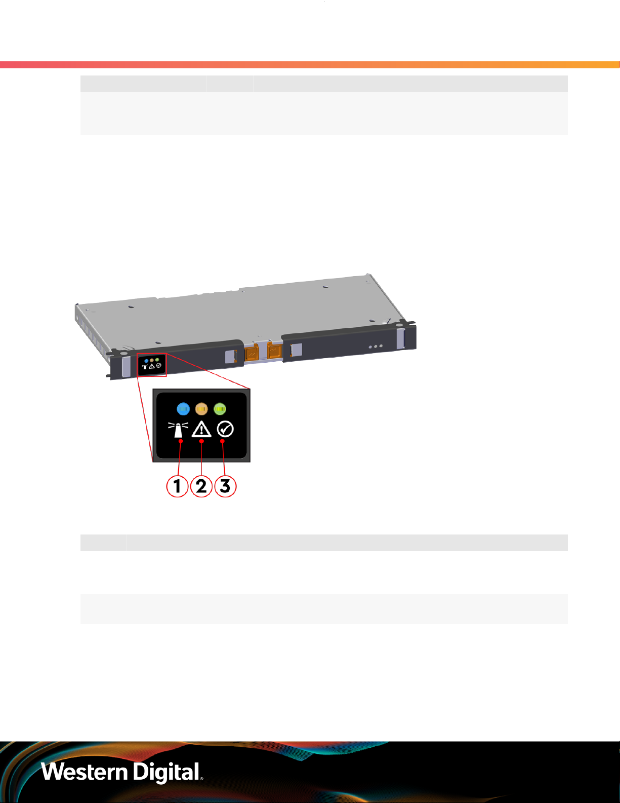
1.11.2 IOM LEDs
The IOM has three LEDs, one each for power, fault, and identification.
Figure 8: IOM LEDs Location
Table 10: IOM LEDs Identification
Number LED Name Color Behavior
1 IOM Identification Blue Blink @ 0.5 Hz (75% duty cycle) – Blinks only when IOM
Identification has been activated
Off - Not being identified
2 IOM Fault Amber Blink @ 0.5 Hz (75% duty cycle) – IOM has Fault
Off - IOM is functioning normally
3 IOM Power Green Solid – IOM is on
Off – IOM is off
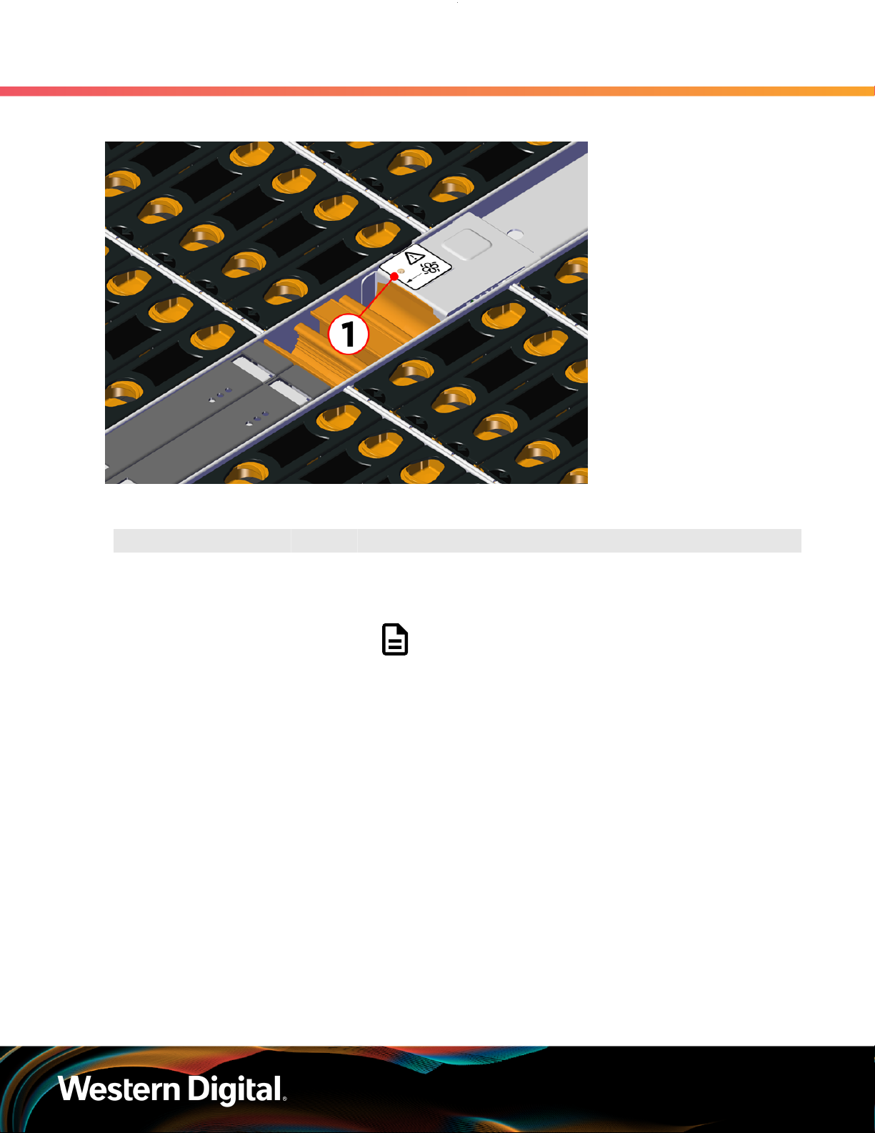
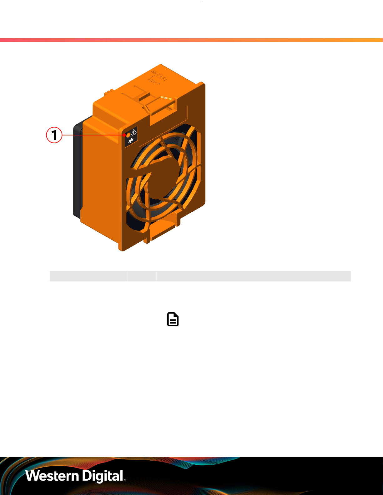
1.11.3 IOM Fan LED
The IOM Fan has a single LED with three distinct states for fault condition, identification, and power off.
11
User Guide
Figure 9: IOM Fan LED Location
1. Overview
1.11 LEDs
Table 11: IOM Fan LED Identification
Number LED Name Color Behavior
1 IOM Fan LED Amber Blink @ 2 Hz (50% duty cycle) – IOM Fan is being identified
Blink @ 1 Hz (50% duty cycle) – IOM Fan is reporting faults
Off – IOM Fan is on and reporting no faults
Note: LEDs have a 50% duty cycle (On for 2
seconds, off for less than a second).
1.11.4 PSU LED
The PSU has a single, multi-function LED. See the table below for a detailed functional description.
12

User Guide
Figure 10: PSU LEDs Location
1. Overview
1.11 LEDs
Table 12: PSU LEDs Identification
Number LED Name Color Behavior
1 PSU Multi-
Function LED
Green Solid – PSU is on and reporting no faults
Blink @ 2Hz (50% duty cycle) – PSU in firmware update mode
Off – PSU is disconnected from power
Amber Solid – PSU is disconnected from power or critical fault
causing a shutdown failure
Blink @ 0.5Hz (50% duty cycle) – PSU reporting warnings
Off – PSU is reporting no faults
Note: LEDs have a 50% duty cycle (On for 2
seconds, off for less than a second).
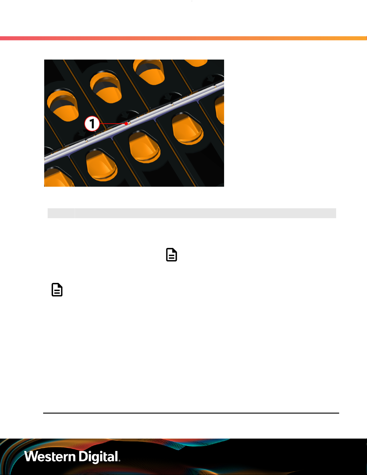
1.11.5 Rear Fan LED
The Rear Fan has a single LED with three distinct states for indicating a fault condition, identification, or
normal operation.
13
User Guide
Figure 11: Fan LED Location
1. Overview
1.11 LEDs
Table 13: Fan LED Identification
Number LED Name Color Behavior
1 Fan LED Amber Blink @ 1 Hz (50% duty cycle) – Fan is reporting faults
Blink @ 2 Hz (50% duty cycle) – Fan is being identified
Off – Fan is on and reporting no faults
Note: LEDs have a 50% duty cycle (On for 2
seconds, off for less than a second).
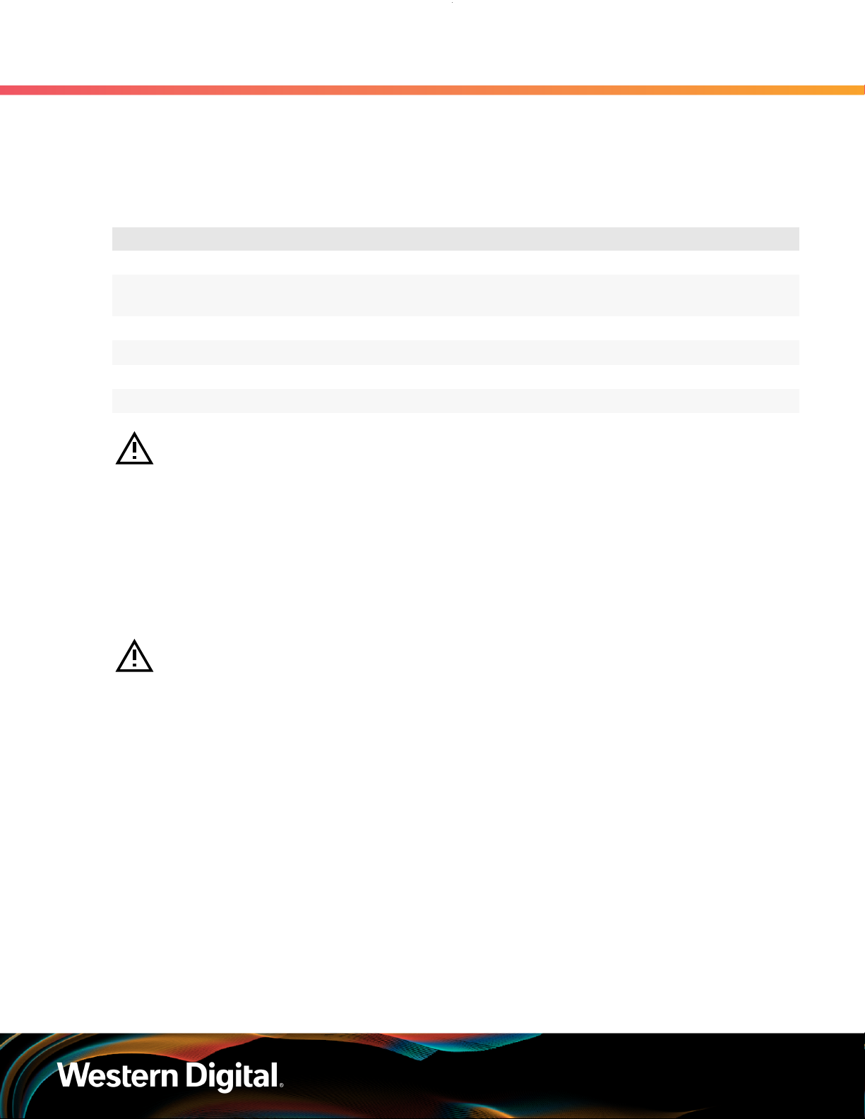
1.11.6 Drive Assembly LED
The HDD drive assembly itself does not contain an LED, but it contains a light-pipe that displays the
multi-function LED located on the drive slot. This amber LED has three distinct states for indicating a fault
condition, identification, or normal operation.
14
User Guide
Figure 12: HDD Assembly LED Location
1. Overview
1.12 Ultrastar Data102 Rack Requirements
Table 14: HDD Assembly LED Identification
Number LED Name Color Behavior
1 HDD Drive Multi-
Function LED
Note: During service events—when a drive is hot plugged or replaced and the drive installed
properly—the LED state of that drive slot will change to solid ON. This is to provide the user
with visual feedback that the drive has been successfully connected and has been discovered
by the expander. Once the enclosure has been slid back into the rack and the OPEN bit on the
door sensor element is 0, the LED will return to the previously set state (Ident, Fault, or Off).
For example: A drive in slot 0 needs to be replaced. The fault bit on Array Slot descriptor
0 is set to indicate to the service technician which drive slot to replace. This will cause the
LED to blink at 1Hz (50% duty cycle). When the service technician pulls out the enclosure,
inserts a new drive, and successfully installs the drive, the slot LED state will change to solid
ON to indicate that the drive was properly installed. When the service technician pushes the
enclosure back into the rack and the OPEN bit of the door sensor element changes from 1
to 0, the LED state of drive slot 0 will change back to the fault indication blink rate (1 Hz 50%
duty cycle).
Amber Blink @ 2 Hz (50% duty cycle) – Drive identify
Blink @ 1 Hz (50% duty cycle) – Drive fault
Off – Drive has no faults
Note: LEDs have a 50% duty cycle (On for 2
seconds, off for less than a second).
1.12 Ultrastar Data102 Rack Requirements
15
User Guide
The Ultrastar Data102 is designed to be installed into a rack that meets the EIA-310 standard at a minimum
1181-1197 mm (46.5in. - 47.13in.) of usable rack space, frame to frame. The vertical rack rails must be set
between 812.8mm - 914.4mm / 32 in. - 36 in. to support the enclosure. It requires 4U of rack space, and it
should be installed into the rack at the lowest possible U height to keep the load on the rack balanced.
Table 15: Required Rack Specifications
1. Overview
1.12 Ultrastar Data102 Rack Requirements
Parameter Requirement
Rack Depth 1181-1197 mm (46.5in. - 47.13in.) of usable rack space, frame to frame
Rack Width
Rack Units (U) 4U
Vertical Rack Rail Spacing 812.8mm - 914.4mm / 32 in. - 36 in.
Static Load Rating 1360.7 kg. / 3000 lbs.
Dynamic Load Rating 1020.5 kg. / 2250 lbs.
Warning: When extended out of the rack on the rail system, the Ultrastar Data102 will be
~950 mm / 37.4in. extended outward. This may be a potential tipping hazard depending on
the configuration of the rack. Ensure that leveling feet, anti-tilt, and any other safety features
recommended by the specific rack manufacturers have been deployed before servicing.
The following section provides specific information necessary to install, service, and remove the Ultrastar
Data102 . The installation of the Ultrastar Data102 requires two people and a space of 1524mm / 60in.
in front of the installation space. The servicing of the enclosure requires one person and a minimum of
1219.2mm / 48in. of space in front of the installation space. The removal of the enclosure requires two
people, 1371mm / 54in. of space in front of the installation space, and 24in. on either side of the enclosure
for two people to remove the enclosure.
Warning: The handles on the front of the chassis are not intended to be used to support the
weight of the Ultrastar Data102 . Lifting the unit by the chassis handles or trying to support the
unit on the handles can cause them to fail. This can cause serious damage to the unit or serious
bodily harm to those handling the unit. Always team lift the chassis by gripping the underside
of the unit, and never try to lift a chassis that is filled with drives.
450mm with (17.72in.) with 465mm (18.31in.) ± 1.5mm
nominal hole spacing. See EIA-310 Rack Standard
16

User Guide
Figure 13: Installation, Servicing, and Removal
1. Overview
1.12 Ultrastar Data102 Rack Requirements
Attention: Do not install or remove the enclosure while it is populated with drives. The fully
populated enclosure exceeds the amount of weight that a team of two should lift.
1.12.1 Compatible Rack Hardware Configuration
The following table(s) list the approved rack hardware configurations for the Ultrastar Data102 :
Table 16: Compatible Hardware Configuration 1
Parameter Rack PDU (Vertical)
Vendor CRENLO/EMCOR Server Technology Server Technology Various
AS-160099-03
(Drawing
Number EMCOR
Part
Number
Quantity 1 2 2 Varies
526121 Rev 5)
412-0761-11_STV-4501
412-0761-20_STV-4502
412-0761-23_STV-4503
PDU Mounting
Bracket
KIT-MBVPT-1B
(one kit per PDU)
Additional Mounting
Bracket Hardware
4 x M6 x 16 Hex
Cap Screws
8 x M6 Fender
Washers
4 x M6 Hex Nut
with Nylon Lock
Table 17: Compatible Hardware Configuration 2
Parameter Rack PDU (Vertical)
Vendor AFCO/Legrand Server Technology Server Technology Various
Part
Number
Options:
412-0761-11_STV-4501
PDU Mounting
Bracket
KIT-MB-40 None
Additional Mounting
Bracket Hardware
17

User Guide
1. Overview
1.12 Ultrastar Data102 Rack Requirements
Parameter Rack PDU (Vertical)
42RU –
WEDIT605
45RU –
WEDIT604
48RU –
WEDIT603
51RU –
WEDIT606
Quantity 1 rack 2 1 N/A
412-0761-20_STV-4502
412-0761-23_STV-4503
PDU Mounting
Bracket
Additional Mounting
Bracket Hardware
Table 18: Compatible Hardware Configuration 3
Parameter Rack PDU (Vertical)
Vendor TRIPP LITE Server Technology Server Technology Various
Options:
SR42UBDP (Rack)
412-0761-11_STV-4501
412-0761-20_STV-4502
PDU Mounting
Bracket
KIT-MBVPT-1B None
Additional Mounting
Bracket Hardware
SREXTENDER
25U (Rack
Part
Number
Quantity 1 rack 2 1 N/A
Extension)
SREXTENDER
42U (Rack
Extension)
SREXTENDER
48U (Rack
Extension)
412-0761-23_STV-4503
Table 19: Compatible Hardware Configuration 4
Parameter Rack PDU (Vertical)
Vendor APC/Schneider Server Technology Server Technology Various
AR3300W
Part
Number
412-0761-11_STV-4501
412-0761-20_STV-4502
412-0761-23_STV-4503
PDU Mounting
Bracket
KIT-MBVPT-1B
(one kit per PDU)
Additional Mounting
Bracket Hardware
4 x M6 x 16 Hex
8 x M6 Fender
Cap Screws
Washers
4 x M6 Hex Nut
with Nylon Lock
18
 Loading...