


User Guide
Ultrastar Data60
Regulatory Model: H4060-J
December 2020
Rev. 1.18
1ET1101

User Guide Table of Contents
Table of Contents
Revision History.................................................................................................................................... vi
Notices....................................................................................................................................................x
Points of Contact.................................................................................................................................. xi
Product Label Information..............................................................................................................xi
Chapter 1. Overview.........................................................................................................1
Ultrastar Data60 Description............................................................................................................... 2
System Architecture Overview........................................................................................................... 2
System Level Block Diagram...............................................................................................................3
Environmental Specifications...............................................................................................................4
Electrical Specifications....................................................................................................................... 4
Mechanical Specifications....................................................................................................................5
Performance Specifications................................................................................................................. 6
Ultrastar Data60 Layout....................................................................................................................... 6
List of Customer Replaceable Units (CRUs).......................................................................................7
Supported Operating Systems........................................................................................................... 8
LEDs.......................................................................................................................................................9
Front and Rear IO LEDs................................................................................................................9
IOM LEDs.......................................................................................................................................11
IOM Fan LED................................................................................................................................. 11
PSU LED........................................................................................................................................12
Rear Fan LED................................................................................................................................13
Drive Assembly LED.................................................................................................................... 14
Ultrastar Data60 Rack Requirements.................................................................................................15
Compatible Rack Hardware Configuration................................................................................17
Power Requirements.......................................................................................................................... 19
ESD....................................................................................................................................................... 19
Enclosure Cooling...............................................................................................................................19
i

User Guide Table of Contents
SAS Cabling........................................................................................................................................20
Supported SKUs................................................................................................................................. 22
List of Compatible Drives..................................................................................................................22
Chapter 2. Components................................................................................................34
Chassis.................................................................................................................................................35
Chassis Specifications................................................................................................................ 35
Chassis Layout.............................................................................................................................36
IOM...................................................................................................................................................... 38
IOM Specifications...................................................................................................................... 38
IOM Layout.................................................................................................................................. 39
IOM Blank.....................................................................................................................................39
PSU...................................................................................................................................................... 40
PSU Specifications...................................................................................................................... 40
PSU Layout................................................................................................................................... 41
Rear Fan.............................................................................................................................................. 42
Rear Fan Specifications.............................................................................................................. 42
Rear Fan Layout.......................................................................................................................... 43
IOM Fan............................................................................................................................................... 44
IOM Fan Specifications............................................................................................................... 44
IOM Fan Layout........................................................................................................................... 45
Rails......................................................................................................................................................46
Rails Specifications..................................................................................................................... 46
Rails Layout..................................................................................................................................47
Rear Cover Alignment Bracket.................................................................................................. 48
CMA..................................................................................................................................................... 49
CMA Specifications..................................................................................................................... 49
CMA Layout.................................................................................................................................50
CMA Cable Tray...........................................................................................................................51
3.5in HDD Assembly.......................................................................................................................... 52
ii

User Guide Table of Contents
3.5in HDD Assembly Specifications.......................................................................................... 52
3.5in HDD Assembly Layout...................................................................................................... 53
3.5in Drive Blank......................................................................................................................... 54
2.5in SSD Assembly........................................................................................................................... 55
Operating the 2.5" Drive Carrier............................................................................................... 55
Chapter 3. Support........................................................................................................58
Part Replacement Service Window................................................................................................. 59
IOM Replacement...............................................................................................................................59
PSU Replacement...............................................................................................................................62
Rear Fan Replacement.......................................................................................................................66
IOM Fan Replacement........................................................................................................................69
3.5in HDD Assembly Replacement....................................................................................................71
CMA Replacement..............................................................................................................................75
Rails Replacement..............................................................................................................................90
Chassis Replacement........................................................................................................................ 119
Special Considerations for Cable Routing......................................................................................154
Cabling for CMA............................................................................................................................... 156
Before You Begin.......................................................................................................................156
Cabling CMA.............................................................................................................................. 157
Chapter 4. Management.............................................................................................. 159
Management Overview.................................................................................................................... 160
Firmware Features Overview..........................................................................................................160
Firmware Upgrade.............................................................................................................................161
Downloading Firmware from the Support Portal.................................................................... 161
Linux Upgrade Preparation....................................................................................................... 163
Linux Upgrade to New Firmware.............................................................................................165
Non-Automatic Firmware Activation in Linux.......................................................................... 167
Windows Firmware Upgrade Preparation...............................................................................169
iii

User Guide Table of Contents
Windows Upgrade to New Firmware..................................................................................... 170
Non-Automatic Firmware Activation in Windows...................................................................173
OOBM Management Overview........................................................................................................ 176
Configuring OOBM Network Settings Using SES.................................................................... 176
Upgrading Firmware with OOBM.............................................................................................178
SES Page 02......................................................................................................................................180
Zoning................................................................................................................................................180
Before Zoning............................................................................................................................180
Predefined Zoning Configurations...........................................................................................180
sg_senddiag Command............................................................................................................188
Enabling Zoning using Linux.................................................................................................... 188
Disabling Zoning using Linux....................................................................................................192
Enabling Zoning using Windows.............................................................................................195
Disabling Zoning using Windows............................................................................................198
File-Based Zoning..................................................................................................................... 202
Subenclosure Nickname................................................................................................................... 212
Setting the Subenclosure Nickname........................................................................................212
Partially Populated Enclosures.........................................................................................................214
Partial Population Configurations............................................................................................. 214
Installing Drives.......................................................................................................................... 217
Daisy Chaining..................................................................................................................................220
Daisy Chaining Configurations................................................................................................. 221
One Host Cable Configurations.............................................................................................. 222
Two Host Cable Configurations.............................................................................................. 227
Cabling for Daisy Chaining...................................................................................................... 232
Chapter 5. Safety.........................................................................................................239
Safety Warnings and Cautions........................................................................................................240
Electrostatic Discharge....................................................................................................................240
iv

User Guide Table of Contents
Optimizing Location.........................................................................................................................240
Power Connections.......................................................................................................................... 241
Power Cords......................................................................................................................................241
Rackmountable Systems...................................................................................................................241
Safety and Service........................................................................................................................... 242
Chapter 6. Disclaimers................................................................................................ 243
Restricted Access Location.............................................................................................................244
Safety Compliance........................................................................................................................... 244
Electromagnetic Compatibility (EMC) Class A Compliance..........................................................244
Country Certifications...................................................................................................................... 245
Chapter 7. Regulatory Statements............................................................................246
Europe (CE Declaration of Conformity).......................................................................................... 247
FCC Class A Notice..........................................................................................................................247
ICES-003 Class A Notice—Avis NMB-003, Classe A......................................................................247
Japanese Compliance Statement, Class A ITE...............................................................................247
Taiwan Warning Label Statement, Class A ITE.............................................................................. 248
v

User Guide Revision History
Revision History
Date Revision Comment
November 2017 1.0 Initial release
November 2017 1.1
December 2017 1.2
January 2018 1.2.1 Updated the product name
January 2018 1.3
• The crossbar on the CMA was changed. See CMA (page 49).
• Removed Lowline power specs from Power Requirements (page
19).
• Changed required rack depth, see Mechanical Specifications (page
5).
• Changed typical power consumption, see Electrical Specifications
(page 4).
• Updated LED Flash Patterns, see LEDs (page 9).
• Added active cable support
• Added firmware upgrade section. See Firmware Upgrade (page
161).
• Updated the Non-Op altitude specification. See Environmental
Specifications (page 4).
• Updated information on the 2.5" drive carrier option. See 2.5in SSD
Assembly (page 55).
• Added torque requirements for all screws used in the enclosure.
• Updated the IOM replacement section to account for the possibility
of a firmware mismatch. See IOM Replacement (page 59).
• Updated the drive assembly installation instructions to clarify
the orientation of the drive assemblies. 3.5in HDD Assembly
Replacement (page 71).
April 2018 1.4
May 2018 1.5 Added the Part Replacement Service Window. See: Part Replacement
June 2018 1.6
• Updated Compatible Drives List. See List of Compatible Drives
(page 22).
• Updated the Rack Requirements. See Ultrastar Data60 Rack
Requirements (page 15).
• Updated the Firmware Upgrades. See: Firmware Upgrade (page
161)
Service Window (page 59)
• Updated Compatible Drives List. See List of Compatible Drives
(page 22)
• Updated the Firmware Upgrade section. See Firmware Upgrade
(page 161)
vi

User Guide Revision History
Date Revision Comment
• Updated the Firmware Download section. See Downloading
Firmware from the Support Portal (page 161)
• Updated the System Architecture Overview section. See System
Architecture Overview (page 2)
• Updated the Daisy Chaining section. See Daisy Chaining (page
220)
• Added the Rear Cover Alignment Bracket Description. See Rear
Cover Alignment Bracket (page 48)
November 2018 1.7
May 2019 1.8
May 2019 1.9
• Updated the images in the Daisy Chaining section. See Daisy
Chaining (page 220)
• Updated List of CRUs. See List of Customer Replaceable Units
(CRUs) (page 7)
• Updated Compatible Drives List. See List of Compatible Drives
(page 22)
• Updated the Host Connectivity section. See: SAS Cabling (page
20)
• Changed senddiag commands from images to codeblocks. See
sg_senddiag Command (page 188).
• Updated daisy-chaining tables to match diagrams. See Two Host
Cable Configurations (page 227).
• Corrected OOBM zoning configuration instructions. See Predefined
Zoning Configurations (page 180).
• Added Configuring OOBM Network Settings Using SES (page
176).
• Corrected the system architecture overview. See System
Architecture Overview (page 2).
• Corrected explanation of SATA configuration in Firmware Upgrade
(page 161) section.
June 2019 1.10
June 2019 1.11 Updated the Host Connectivity section. See: SAS Cabling (page 20)
July 2019 1.12
• Updated the Host Connectivity section. See: SAS Cabling (page
20)
• Added Windows syntax examples and reorganized the Upgrading
Firmware with OOBM section
Moved the following topics to the Ultrastar Data60 Description (page
2) section:
• Ultrastar Data60 Rack Requirements (page 15)
• Power Requirements (page 19)
• ESD (page 19)
• Enclosure Cooling (page 19)
vii

User Guide Revision History
Date Revision Comment
• SAS Cabling (page 20)
Moved the Supported Operating Systems (page 8) topic to the
Management (page 159) section.
Corrected LED identification tables for IOMs, PSUs, and drives in the
LEDs (page 9) section.
Updated servicing image to correct length values and rail servicing
extension in Ultrastar Data60 Rack Requirements (page 15) section.
Added a note about OOBM ports configured for DHCP by default to the
OOBM Management Overview (page 176) section.
September 2019 1.13
November 2019 1.14
April 2020 1.15
• Replaced references to He12 drives with Ultrastrar DC HC520 in List
of Compatible Drives (page 22)
• Changed device references from OS-specific (/dev/sgX for Linux
and SCSIX:X,X,X for Windows) to generic (<dev>) throughout.
• Updated table for Approved SAS Cables in SAS Cabling (page
20)
• Added Subenclosure Nickname (page 212) section
• Updated Supported Operating Systems (page 8)
• Added drive assembly LED pointer orientation image in 3.5in HDD
Assembly Replacement (page 71) section
• Updated images of captive chassis-cover screws throughout
• Updated table for Approved SAS Cables in SAS Cabling (page
20)
• Updated the Daisy Chaining configurations in Daisy Chaining (page
220)
• Corrected explanation of expanders in System Architecture
Overview (page 2)
• Added note about using non-automatic firmware activation for RAID
adpaters in Firmware Upgrade (page 161)
• Added note about performing zoning offline in Zoning (page 180)
• Added note and step for configuring zoning on an IOM after
replacement in IOM Replacement (page 59)
• Added RHEL 8.0 to Supported Operating Systems (page 8)
• Added note about LED behavior during proper drive insertion in
Drive Assembly LED (page 14)
• Corrected part number for rail kit in List of Customer Replaceable
Units (CRUs) (page 7) and Rails Specifications (page 46)
• Added note about minimum time between removing and
reapplying power in Power Connections (page 241)
August 2020 1.16
• Updated Supported Operating Systems (page 8)
• Updated SAS Cabling (page 20)
viii

User Guide Revision History
Date Revision Comment
• Updated List of Compatible Drives (page 22)
• Added File-Based Zoning (page 202) section
• Updated note in IOM Replacement (page 59) about standard vs.
file-based zoning configuration after IOM replacement
October 2020 1.17
December 2020 1.18
• Fixed typo in Rails Layout (page 47)
• Updated text and color-coded images in Predefined Zoning
Configurations (page 180)
• Updated images in LEDs (page 9) and Components (page
34)
• Added note about not unzipping tar.gz file prior to firmware
upgrade in Downloading Firmware from the Support Portal
(page 161), Linux Upgrade to New Firmware (page 165), Non-
Automatic Firmware Activation in Linux (page 167), Windows
Upgrade to New Firmware (page 170), and Non-Automatic
Firmware Activation in Windows (page 173)
• Added Ubuntu 20.04 to Supported Operating Systems (page 8)
• Updated table of approved SAS cables in SAS Cabling (page 20)
• Updated FW activation step in Upgrading Firmware with OOBM
(page 178)
• Added UK Import Representation Contact
• Removed Formerica cables from SAS Cabling (page 20)
ix

User Guide Notices
Notices
Western Digital Technologies, Inc. or its affiliates' (collectively “Western Digital”) general policy does not
recommend the use of its products in life support applications wherein a failure or malfunction of the product
may directly threaten life or injury. Per Western Digital Terms and Conditions of Sale, the user of Western
Digital products in life support applications assumes all risk of such use and indemnifies Western Digital
against all damages.
This document is for information use only and is subject to change without prior notice. Western Digital
assumes no responsibility for any errors that may appear in this document, nor for incidental or consequential
damages resulting from the furnishing, performance or use of this material.
Absent a written agreement signed by Western Digital or its authorized representative to the contrary,
Western Digital explicitly disclaims any express and implied warranties and indemnities of any kind that may,
or could, be associated with this document and related material, and any user of this document or related
material agrees to such disclaimer as a precondition to receipt and usage hereof.
Each user of this document or any product referred to herein expressly waives all guaranties and warranties
of any kind associated with this document any related materials or such product, whether expressed or
implied, including without limitation, any implied warranty of merchantability or fitness for a particular
purpose or non-infringement. Each user of this document or any product referred to herein also expressly
agrees Western Digital shall not be liable for any incidental, punitive, indirect, special, or consequential
damages, including without limitation physical injury or death, property damage, lost data, loss of profits or
costs of procurement of substitute goods, technology, or services, arising out of or related to this document,
any related materials or any product referred to herein, regardless of whether such damages are based on
tort, warranty, contract, or any other legal theory, even if advised of the possibility of such damages.
This document and its contents, including diagrams, schematics, methodology, work product, and
intellectual property rights described in, associated with, or implied by this document, are the sole and
exclusive property of Western Digital. No intellectual property license, express or implied, is granted by
Western Digital associated with the document recipient's receipt, access and/or use of this document or the
products referred to herein; Western Digital retains all rights hereto.
Western Digital, the Western Digital logo, and Ultrastar are registered trademarks or trademarks of Western
Digital Corporation or its affiliates in the US and/or other countries. Linux® is the registered trademark of
Linus Torvalds in the U.S. and other countries. All other marks are the property of their respective owners.
Product specifications subject to change without notice. Pictures shown may vary from actual products. Not
all products are available in all regions of the world.
Western Digital
5601 Great Oaks Parkway
San Jose, CA 95119
© 2020 Western Digital Corporation or its affiliates. All Rights Reserved.
x
User Guide Points of Contact
Points of Contact
For further assistance with a Western Digital product, contact Western Digital Datacenter Platforms technical
support. Please be prepared to provide the following information: part number (P/N), serial number (S/N),
product name and/or model number, and a brief description of the issue.
Email:
support@wdc.com
Website:
https://portal.wdc.com/Support/s/
UK Import Representation Contact
Western Digital UK Limited Hamilton House, Regent Park, Kingston Road Leatherhead, Surrey KT22 7PL, GB,
United Kingdom
Telephone: +44 1372 366000
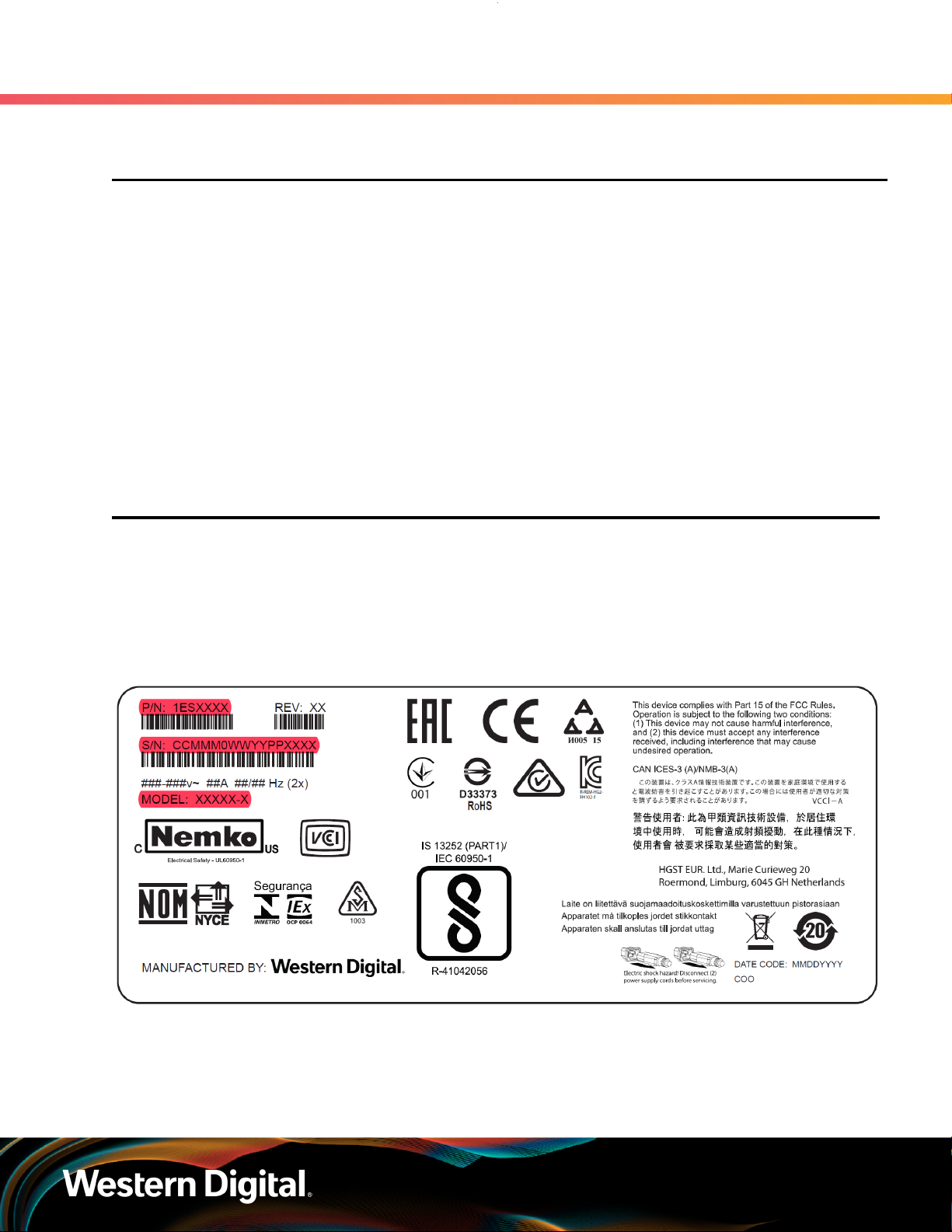
1.1 Product Label Information
The following product information is required for technical support requests:
• Part Number (P/N)
• Serial Number (S/N)
• Product Name and/or Model Number (MODEL)
This information may be found on the product label, which is affixed to an exterior, non-removable surface of
the chassis. The following is an example label with the applicable information fields highlighted:
xi

Western Digital
Overview
This section provides a high level overview of the features of the
Ultrastar Data60 .
In This Chapter:
- System Architecture Overview.....................2
- System Level Block Diagram.........................2
- Environmental Specifications........................3
- Electrical Specifications................................ 4
- Mechanical Specifications............................. 4
- Performance Specifications...........................5
- Ultrastar Data60 Layout................................ 6
- List of Customer Replaceable Units
(CRUs)............................................................... 6
- Supported Operating Systems......................7
- LEDs................................................................. 8
- Ultrastar Data60 Rack Requirements........... 9
- Power Requirements.................................... 15
- ESD..................................................................19
- Enclosure Cooling.........................................19
- SAS Cabling................................................... 19
- Supported SKUs........................................... 20
- List of Compatible Drives............................22
1
User Guide
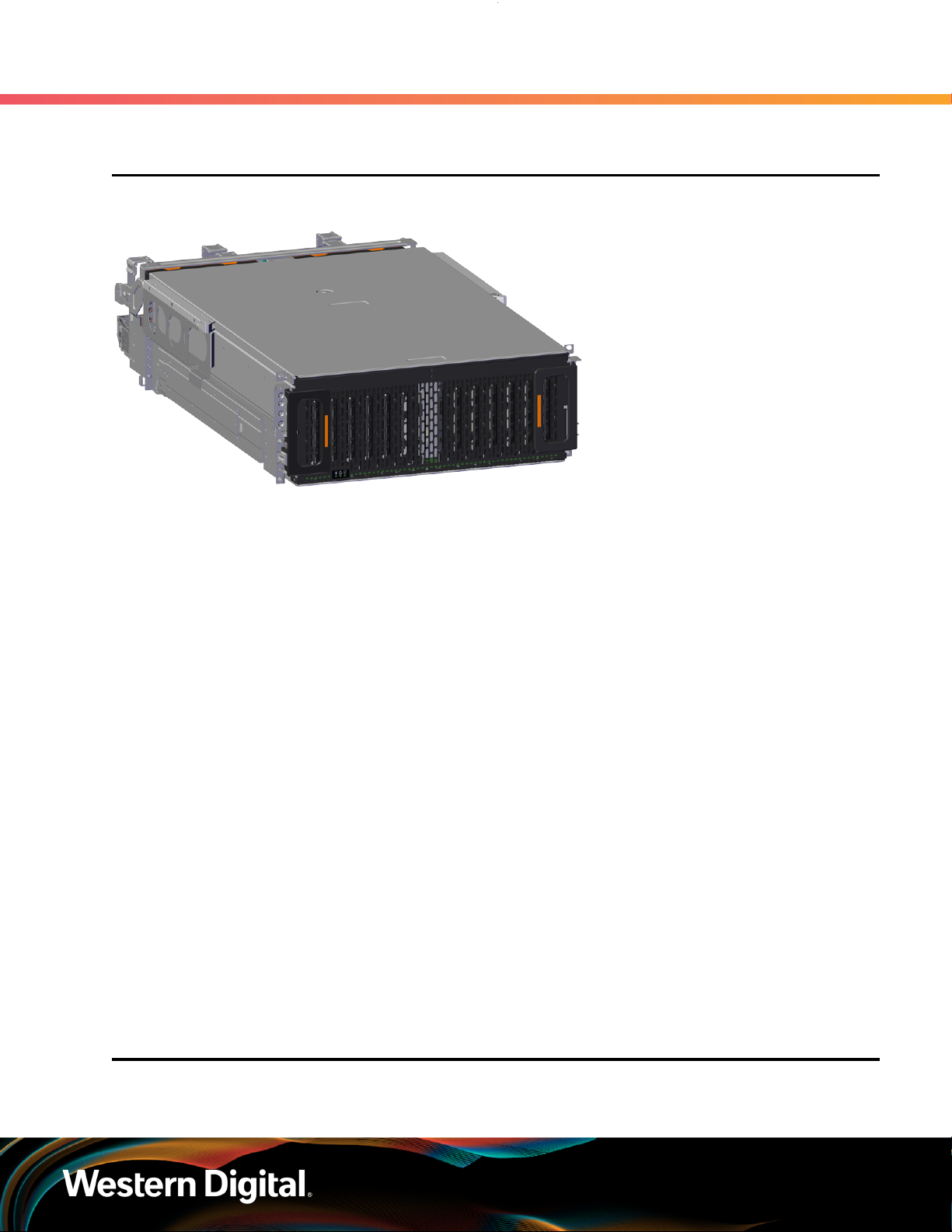
1.1 Ultrastar Data60 Description
Figure 2: Ultrastar Data60
1. Overview
1.1 Ultrastar Data60 Description
The Ultrastar Data60 is a 4U form factor, high availability, high density, rack-mounted storage enclosure
that is capable of hosting up to 60 SAS or SATA drives. The maximum data storage capacity of the Ultrastar
Data60 is 840 TB using 14TB HGST Ultrastar® HC530 drives . (For a full list of compatible drives and total
storage capacities, see the List of Compatible Drives (page 22).) The enclosure runs on an input voltage
of 200 - 240 VAC and consumes ~1000W of power under typical conditions. It requires a maximum of
~1250W at full load.
It is designed to fit within a 4U rack space and requires 900mm (35.43in.) usable rack space, frame to frame.
A fully loaded system will add 79.4 kg. / 175 lbs. of static load when fully loaded with drives.
• 4U Storage Enclosure
• Supports up to 60 Drives
• Can support 3.5” drives and 2.5” SSD drives (2.5" requires an adapter) in the 60 available drive bays.
• Up to 12W per drive slot for the 60 data storage drives (Cannot exceed 85A on the 5V rail)
• House and control four (4) N+1 redundant 80mm rear fans
• House and control a dual rotor 40mm internal IOM Fan
• Controlled by two (2) redundant I/O Modules
• Powered by two (2) redundant 1600W PSUs
• Supports High Line (220-240 VAC) Input Power
• Full high availability with independent dual paths to all HDDs
• Toolless replacement of all Customer Replaceable Units (CRUs)
• Fits within a standard EIA-310 rack including all necessary cable management (see Compatible Rack
Hardware Configuration (page 17))
• Supports up to 3m passive SAS cables (limited to 3m or less) or active cables (any length) (see SAS
Cabling (page 20))
1
1.2 System Architecture Overview
1. SATA based models will only include 1 IOM
2

User Guide
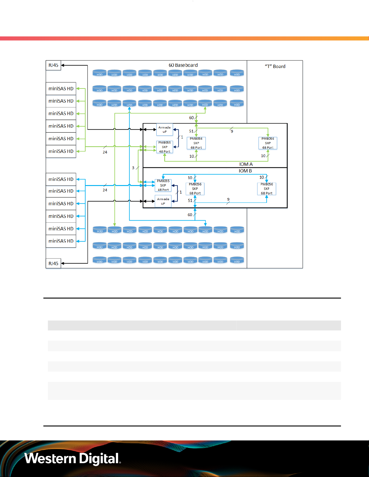
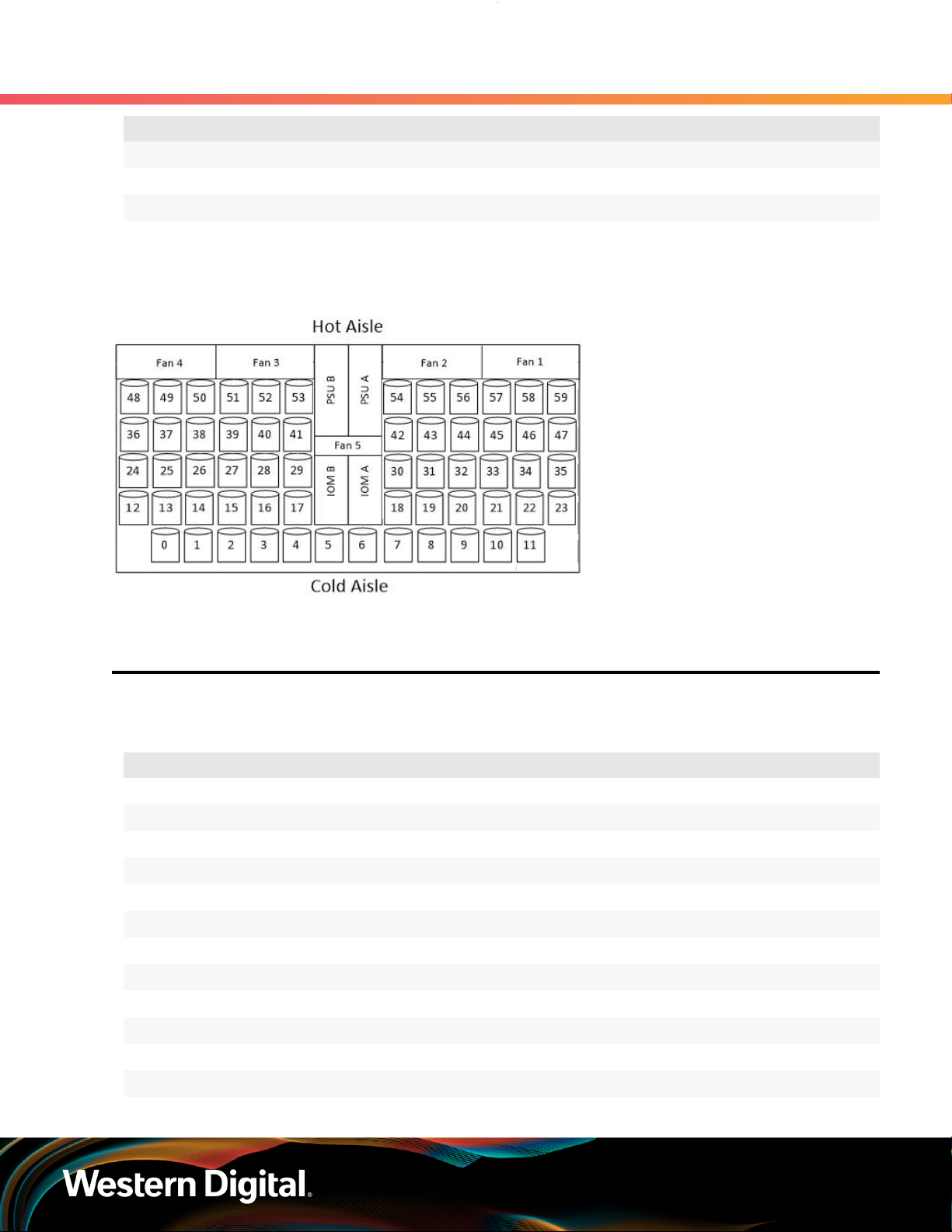
The Ultrastar Data60 IOM uses a cascaded expander design to allow for connection to all 60 drives. A
48-port primary expander connects with the six host ports, has a x3 link to the other IOM for IOM-IOM
communication and syncing, and also has a x10 SAS link to each secondary expander. One secondary
expander then connects with fifty-one (51) drives, while the other connects with nine (9) drives.
The out-of-band management microprocessor provides an Ethernet connection using a Redfish/RESTful
API to access the various enclosure services. All the SES enclosure information can be obtained through the
out-of-band management port. Major use cases for this feature include obtaining storage subsystem health
information, locating enclosure components using the IDENT LEDs, and updating firmware.
The system FPGAs control and report the states of the system fans, enclosure LEDs, connector LEDs, drive
LEDs, and T10 drive power disable signals on the 60 data storage drives.
The I2C architecture is designed to support only one single master on any given bus. The primary expander
will be the master on each I2C bus. There are eight I2C buses used in the Ultrastar Data60 enclosure.
The number of devices on each bus are balanced to allow communication to peripheral devices and not
overload any one bus. The devices connected on the I2C buses include the enclosure VPDs, temp sensors,
baseboard FPGAs, and SAS connectors among others.
1. Overview
1.3 System Level Block Diagram
Note: To use T10 power disable, the drives installed must also support this feature.
1.3 System Level Block Diagram
The following image shows the system block diagram for the Ultrastar Data60 .
3
User Guide
Figure 3: System Block Diagram
1. Overview
1.4 Environmental Specifications
1.4 Environmental Specifications
Table 1: Environmental Specification Summary
Specification Non-Operational Operational
Temperature -40°C to 70°C 5°C to 35°C
Temperature Gradient 30°C / Hr 20°C per hour maximum
Temperature De-rating 1°C per 300m above 3000m 1°C per 300m above 900m
Relative Humidity 8-90% Non-Condensing 8-90% Non-Condensing
Relative Humidity Gradient 30% per hour maximum 30% per hour maximum
Altitude -300m to 12,000m /
-984 ft. to 39,370 ft
1.5 Electrical Specifications
-300m to 3048m /
-984 ft. to 10,000 ft.
4

User Guide
Table 2: Electrical Specifications
Specification Value
Max Power Consumption ~1250W
Typical Power Consumption
Input Voltage 200 - 240 VAC
PSU Connector Type C14
PSU Efficiency 80 PLUS Platinum
2
1. Overview
1.6 Mechanical Specifications
~1000W
Inrush Current Maximum (per
PSU)
Caution: The Ultrastar Data60 can only be plugged into high line (200 - 240 VAC) power. If
the unit is plugged into low line (110-127 VAC), the PSU will report a "Critical" state when status
pages are queried using SES. In this case, the enclosure will power up, but the drives will not.
The enclosure will remain in low-power mode.
AC line inrush current shall not exceed 40A peak, for up to
one-quarter of the AC cycle after which, the input current
should be no more than the specified maximum input current.
1.6 Mechanical Specifications
Table 3: Mechanical Specifications
Specification Non-Operational Operational
Shock 10G, 0 - peak,11ms half sine;
3 positive and 3 negative
pulses in each axis Shock
Vibration 0.75G, 0 - peak swept sine;
5 -500Hz; 1 complete sweep
@ 1/2 octave per minute
5G, 0 - peak, 11ms half sine; 3 positive
and 3 negative pulses in each axis-
minimum 6 seconds between shocks
to allow for write/read recovery
0.10G,0 - peak swept sine; 5
-500Hz; 1 complete sweep
@ 1/2octave per minute
Weight 79.4 kg. / 175 lbs.
Dimensions 447mm x 890mm x 175mm / 17.67in. x 35.04in. x 6.89in.
Length without CMA 712 mm / 28.03in.
Required Rack Width 450mm (17.72in.) with 465mm (18.31in.) ± 1.5mm
nominal hole spacing. See EIA-310 Rack Standard
Required Rack Depth 900mm (35.43in.) usable rack space, frame to frame
Rack Units (U) 4U
2. Max and typical power consumption values represent the output power to the system. Input power will vary depending
on the PSU efficiency and load sharing between PSUs.
5
User Guide
Specification Non-Operational Operational
Vertical Rack Rail
Spacing
1.7 Performance Specifications
Table 4: Performance Specifications
Specification Value
Number of Drive Slots 60
Data Transfer Rates 12Gbps SAS / 6Gbps SATA
Max Raw Data Storage Capacity 840 TB using 14TB HGST Ultrastar® HC530 drives
SAS Ports 12 x Mini-SAS HD ( 6 per IOM)
1. Overview
1.7 Performance Specifications
24 in. - 32 in.
2 x 10/100/1G Ethernet
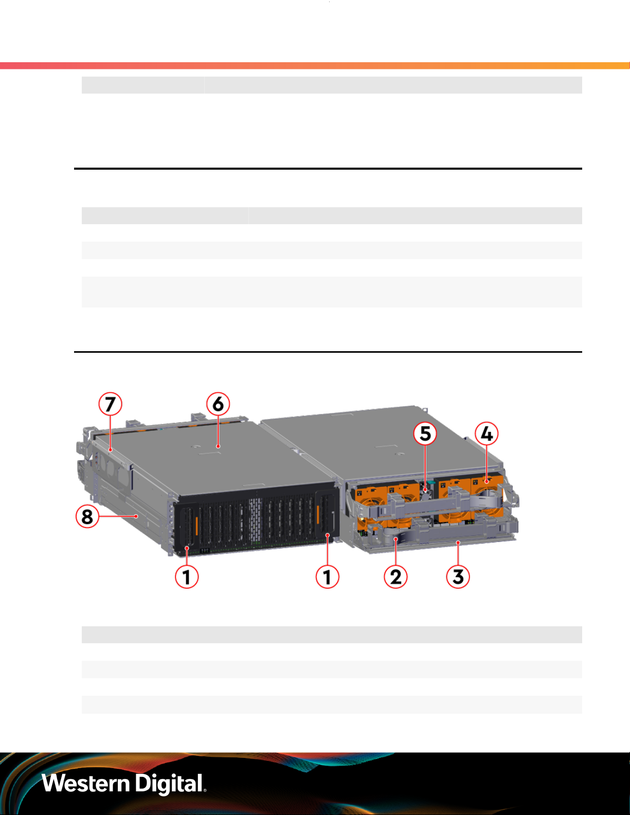
1.8 Ultrastar Data60 Layout
Figure 4: Front and Rear Product Layout
Table 5: Front and Rear Component Identification
Number Component
1 Enclosure Handles
2 CMAs
3 CMA Tray
4 Rear Fans
5 PSUs
6
User Guide
The following is an image of the layout of the major system components inside the Ultrastar Data60 .
Figure 5: Component Layout
1. Overview
1.9 List of Customer Replaceable Units (CRUs)
Number Component
6 Chassis Cover
7 Rear Cover Alignment Brackets
8 Rails
1.9 List of Customer Replaceable Units (CRUs)
The following table lists the replaceable components and their part numbers.
Table 6: List of Replaceable Components
Component Part Number
Ultrastar Data60 Chassis with a single IOM and PSUs 1EX0442
Ultrastar Data60 Chassis with IOMs and PSUs 1EX0443
IOM 1EX2201
IOM Blank 1EX0431
PSU 1600W 1EX0434
Rear Fan 1EX0433
IOM Fan 1EX0432
Rails (CMA Standard) 1EX0436
Rear Cover Alignment Bracket 1EX2288
CMA Standard Arms 1EX0437
CMA Cable Tray 1EX1119
3.5 in. Drive Carrier, Qty=1 1EX0438
7

User Guide
Component Part Number
3.5 in. to 2.5 in. conversion Drive Carrier, Qty=1 1EX0439
3.5 in. Drive Blank, Qty=1 1EX0429
Power Cable for PDU, C13-C14, 18AWG, 3m, Qty=1 1EX1158
HD Mini-SAS to HD Mini-SAS, 3m, Qty=2 1EX1533
1.10 Supported Operating Systems
Table 7: Compatible Operating Systems
OS Support
Microsoft® Windows
1. Overview
1.10 Supported Operating Systems
2012 R2 x64 Server
2016 R1 x64 Server
2019 R1 x64 Server
CentOS/RedHat® Enterprise Linux (RHEL)
Ubuntu® Server
7.2 (x86_64) Kernel: 3.10.0-327
7.3 (x86_64) Kernel: 3.10.0-514
7.4 (x86_64) Kernel: 3.10.0-693
7.6 (x86_64) Kernel: 3.10.0-957
8.0 (x86_64) Kernel: 4.18.0-80
8.2 (x86_64) Kernel: 4.18.0-193
14.04 Kernel: 3.13
16.04 Kernel: 4.4
18.04 Kernel: 4.15
20.04
8.10 Kernel: 3.16Debian GNU/Linux
9.6 Kernel: 4.9
12 SP3SUSE® Linux Enterprise Server (SLES)
15 SP1
8
User Guide
1.11 LEDs
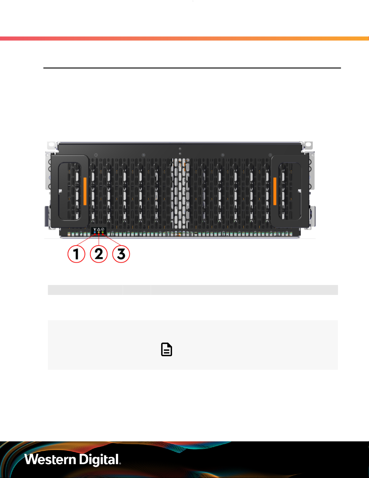
1.11.1 Front and Rear IO LEDs
The Ultrastar Data60 has a number of LEDs on the exterior of the enclosure that display various system
statuses. The three LEDs on the front mirror three on the rear, allowing the general status of the enclosure
to be determined from either side of the rack.
Figure 6: Front LEDs Location
1. Overview
1.11 LEDs
Table 8: Front LEDs Identification
Number LED Name Color Behavior
1 Identify Blue Blink @ 1 Hz (50% duty cycle) – Blinks only when Identification
has been activated. Will blink when any component is
identified.
2 Fault Amber Blink @ 1 Hz (50% duty cycle) – Enclosure has a fault
Off – Enclosure has no fault
Note: LEDs have a 50% duty cycle (On for 2
seconds, off for less than a second).
3 Power Green Solid – Powered On
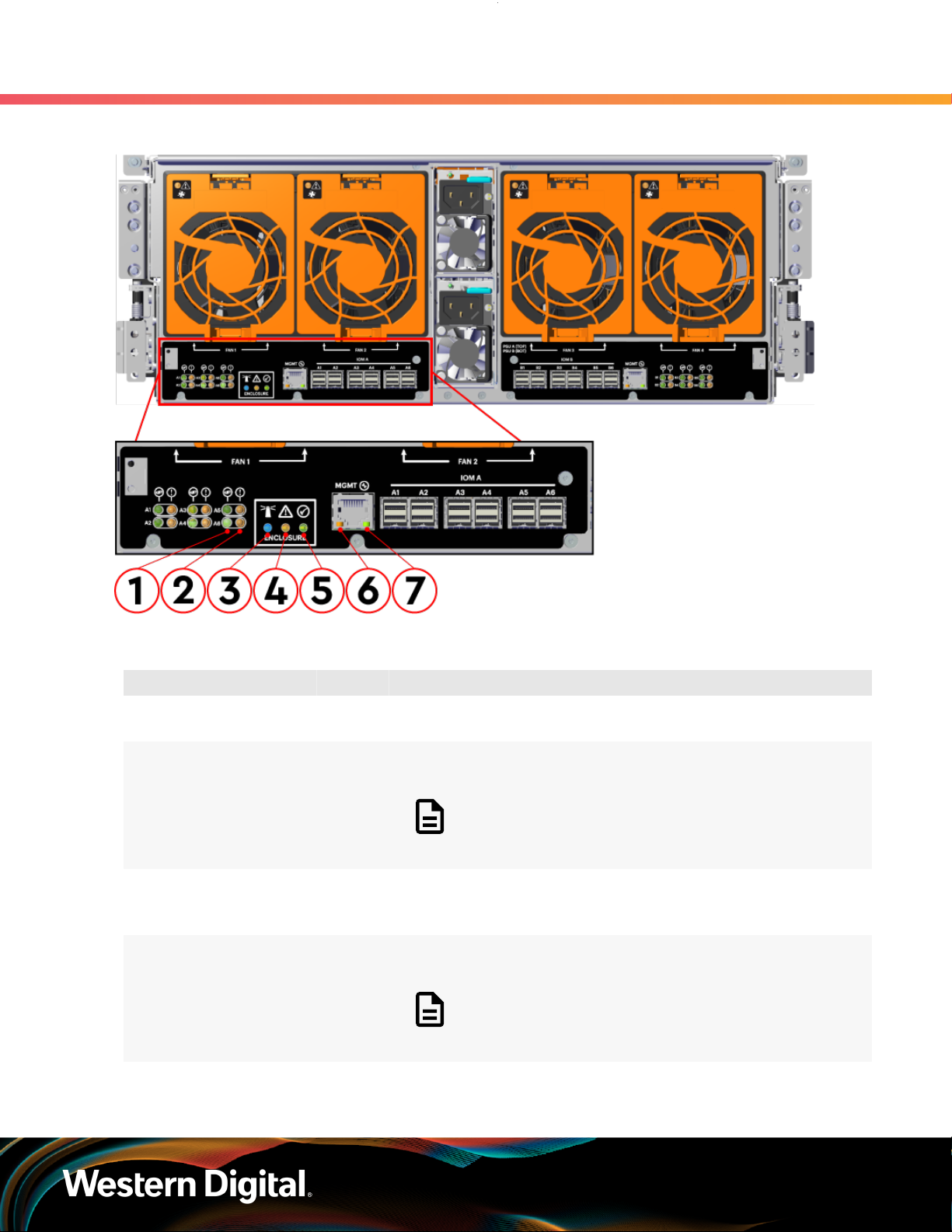
In addition to the three enclosure status LEDs, the rear provides LEDs for the Ethernet and SAS ports.
9
User Guide
Figure 7: Rear LEDs Location
1. Overview
1.11 LEDs
Table 9: Rear LEDs Identification
Number LED Name Color Behavior
1 SAS Link Status Green Solid – SAS cable connected
Off – SAS cable not connected
2 SAS Fault
Status
3 Identification Blue Blink @ 1 Hz (50% duty cycle) – Blinks only when Identification
4 Fault Amber Blink @ 1 Hz (50% duty cycle) – Enclosure has a fault
5 Power Green Solid – Powered On
Amber Blink @ 1 Hz (50% duty cycle) – SAS connection fault
Off – No SAS connection fault
Note: LEDs have a 50% duty cycle (On for 2
seconds, off for less than a second).
has been activated. Will blink when any component is
identified.
Off – Enclosure has no fault
Note: LEDs have a 50% duty cycle (On for 2
seconds, off for less than a second).
10
User Guide
Number LED Name Color Behavior
6 Ethernet
Connector
Speed
Green/
Amber
1. Overview
1.11 LEDs
Off – Operating at 10 Mbps
Green Solid – Operating at 100 Mbps
Amber Solid – Operating at 1Gpbs
7 Ethernet
Connectors
Link/Activity
Green Off – No Connection
Solid – Connected
Blink – Activity
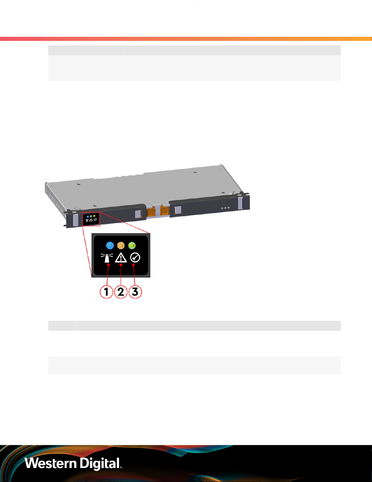
1.11.2 IOM LEDs
The IOM has three LEDs, one each for power, fault, and identification.
Figure 8: IOM LEDs Location
Table 10: IOM LEDs Identification
Number LED Name Color Behavior
1 IOM Identification Blue Blink @ 0.5 Hz (75% duty cycle) – Blinks only when IOM
Identification has been activated
Off - Not being identified
2 IOM Fault Amber Blink @ 0.5 Hz (75% duty cycle) – IOM has Fault
Off - IOM is functioning normally
3 IOM Power Green Solid – IOM is on
Off – IOM is off
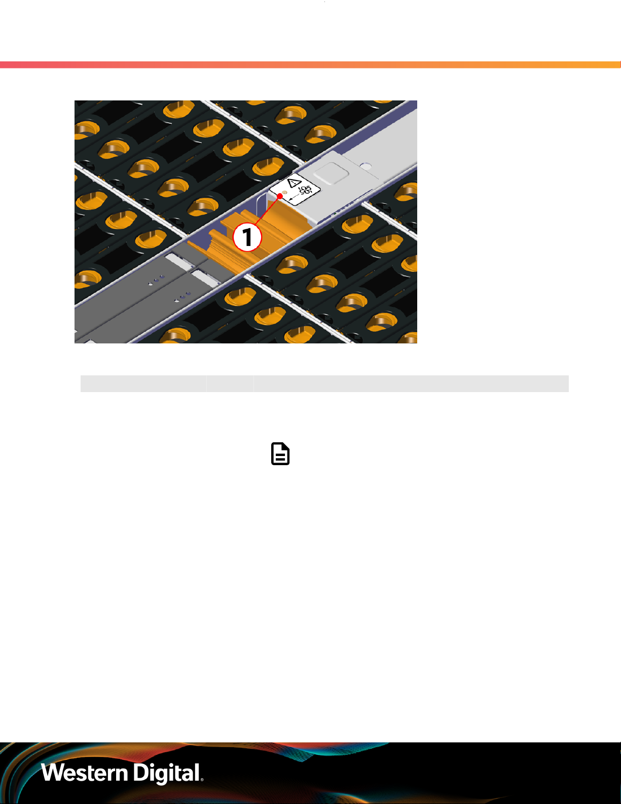
1.11.3 IOM Fan LED
The IOM Fan has a single LED with three distinct states for fault condition, identification, and power off.
11
User Guide
Figure 9: IOM Fan LED Location
1. Overview
1.11 LEDs
Table 11: IOM Fan LED Identification
Number LED Name Color Behavior
1 IOM Fan LED Amber Blink @ 2 Hz (50% duty cycle) – IOM Fan is being identified
Blink @ 1 Hz (50% duty cycle) – IOM Fan is reporting faults
Off – IOM Fan is on and reporting no faults
Note: LEDs have a 50% duty cycle (On for 2
seconds, off for less than a second).
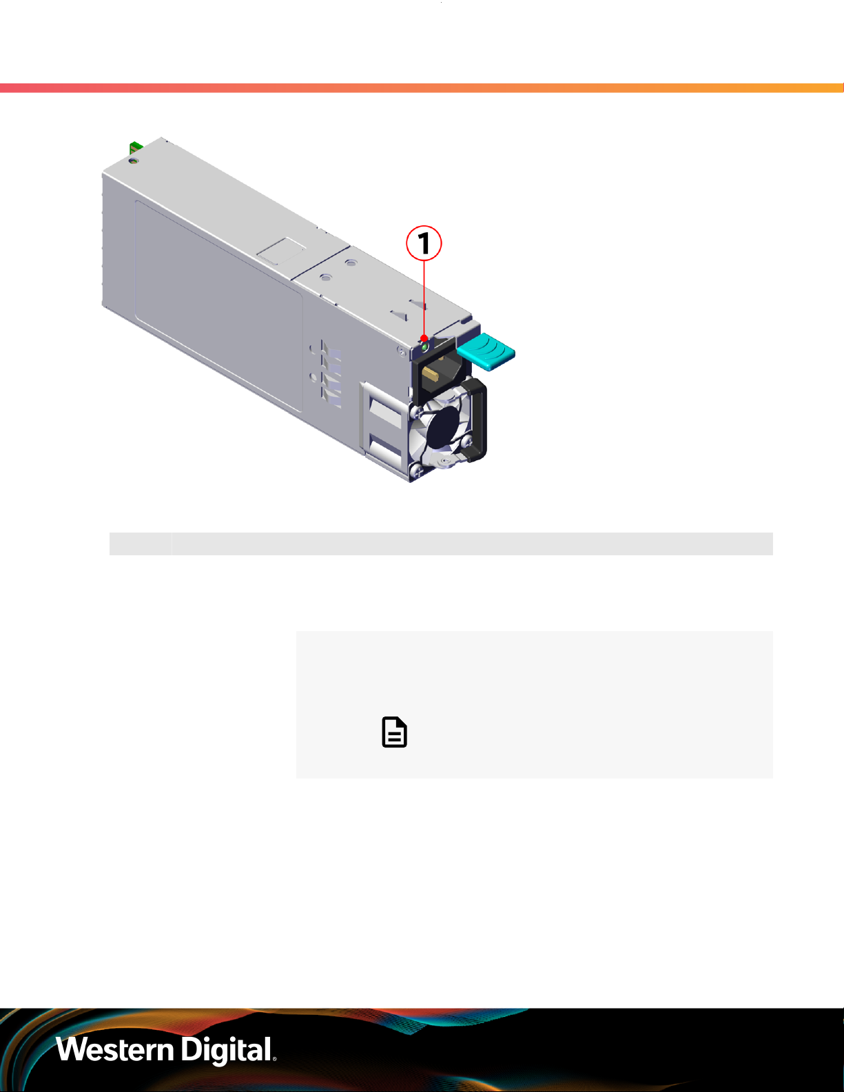
1.11.4 PSU LED
The PSU has a single, multi-function LED. See the table below for a detailed functional description.
12
User Guide
Figure 10: PSU LEDs Location
1. Overview
1.11 LEDs
Table 12: PSU LEDs Identification
Number LED Name Color Behavior
1 PSU Multi-
Function LED
Green Solid – PSU is on and reporting no faults
Blink @ 2Hz (50% duty cycle) – PSU in firmware update mode
Off – PSU is disconnected from power
Amber Solid – PSU is disconnected from power or critical fault
causing a shutdown failure
Blink @ 0.5Hz (50% duty cycle) – PSU reporting warnings
Off – PSU is reporting no faults
Note: LEDs have a 50% duty cycle (On for 2
seconds, off for less than a second).
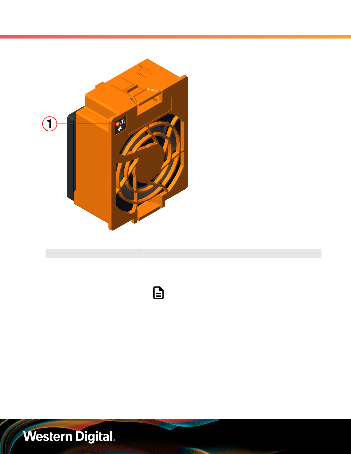
1.11.5 Rear Fan LED
The Rear Fan has a single LED with three distinct states for indicating a fault condition, identification, or
normal operation.
13
User Guide
Figure 11: Fan LED Location
1. Overview
1.11 LEDs
Table 13: Fan LED Identification
Number LED Name Color Behavior
1 Fan LED Amber Blink @ 1 Hz (50% duty cycle) – Fan is reporting faults
Blink @ 2 Hz (50% duty cycle) – Fan is being identified
Off – Fan is on and reporting no faults
Note: LEDs have a 50% duty cycle (On for 2
seconds, off for less than a second).
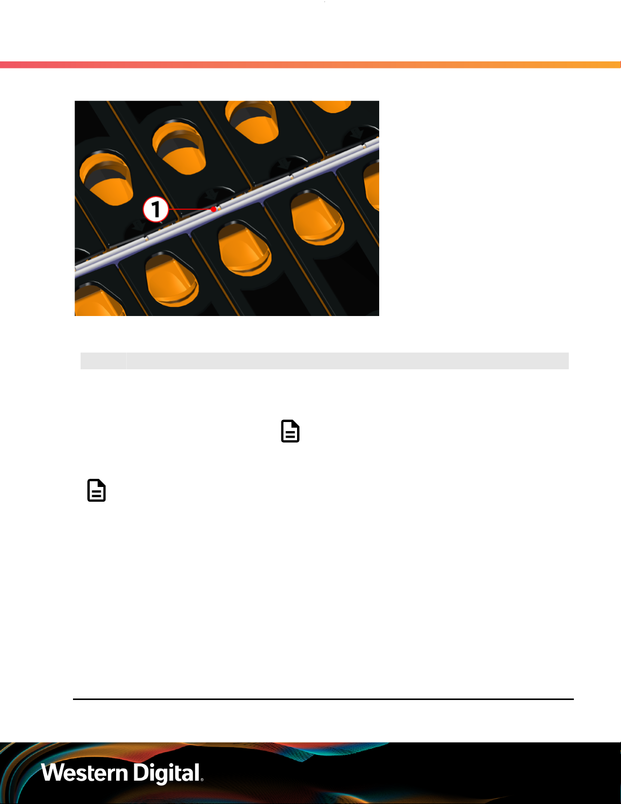
1.11.6 Drive Assembly LED
The HDD drive assembly itself does not contain an LED, but it contains a light-pipe that displays the
multi-function LED located on the drive slot. This amber LED has three distinct states for indicating a fault
condition, identification, or normal operation.
14
User Guide
Figure 12: HDD Assembly LED Location
1. Overview
1.12 Ultrastar Data60 Rack Requirements
Table 14: HDD Assembly LED Identification
Number LED Name Color Behavior
1 HDD Drive Multi-
Function LED
Note: During service events—when a drive is hot plugged or replaced and the drive installed
properly—the LED state of that drive slot will change to solid ON. This is to provide the user
with visual feedback that the drive has been successfully connected and has been discovered
by the expander. Once the enclosure has been slid back into the rack and the OPEN bit on the
door sensor element is 0, the LED will return to the previously set state (Ident, Fault, or Off).
For example: A drive in slot 0 needs to be replaced. The fault bit on Array Slot descriptor
0 is set to indicate to the service technician which drive slot to replace. This will cause the
LED to blink at 1Hz (50% duty cycle). When the service technician pulls out the enclosure,
inserts a new drive, and successfully installs the drive, the slot LED state will change to solid
ON to indicate that the drive was properly installed. When the service technician pushes the
enclosure back into the rack and the OPEN bit of the door sensor element changes from 1
to 0, the LED state of drive slot 0 will change back to the fault indication blink rate (1 Hz 50%
duty cycle).
Amber Blink @ 2 Hz (50% duty cycle) – Drive identify
Blink @ 1 Hz (50% duty cycle) – Drive fault
Off – Drive has no faults
Note: LEDs have a 50% duty cycle (On for 2
seconds, off for less than a second).
1.12 Ultrastar Data60 Rack Requirements
15

User Guide
The Ultrastar Data60 is designed to be installed into a rack that meets the EIA-310 standard at a minimum
900mm (35.43in.) usable rack space, frame to frame. The vertical rack rails must be set between 24 in. 32 in. to support the enclosure. It requires 4U of rack space, and it should be installed into the rack at the
lowest possible U height to keep the load on the rack balanced.
Table 15: Required Rack Specifications
1. Overview
1.12 Ultrastar Data60 Rack Requirements
Parameter Requirement
Rack Depth 900mm (35.43in.) usable rack space, frame to frame
Rack Width
Rack Units (U) 4U
Vertical Rack Rail Spacing 24 in. - 32 in.
Static Load Rating 1360.7 kg. / 3000 lbs.
Dynamic Load Rating 1020.5 kg. / 2250 lbs.
Warning: When extended out of the rack on the rail system, the Ultrastar Data60 will be
~630mm / 24.8in. extended outward. This may be a potential tipping hazard depending on
the configuration of the rack. Ensure that leveling feet, anti-tilt, and any other safety features
recommended by the specific rack manufacturers have been deployed before servicing.
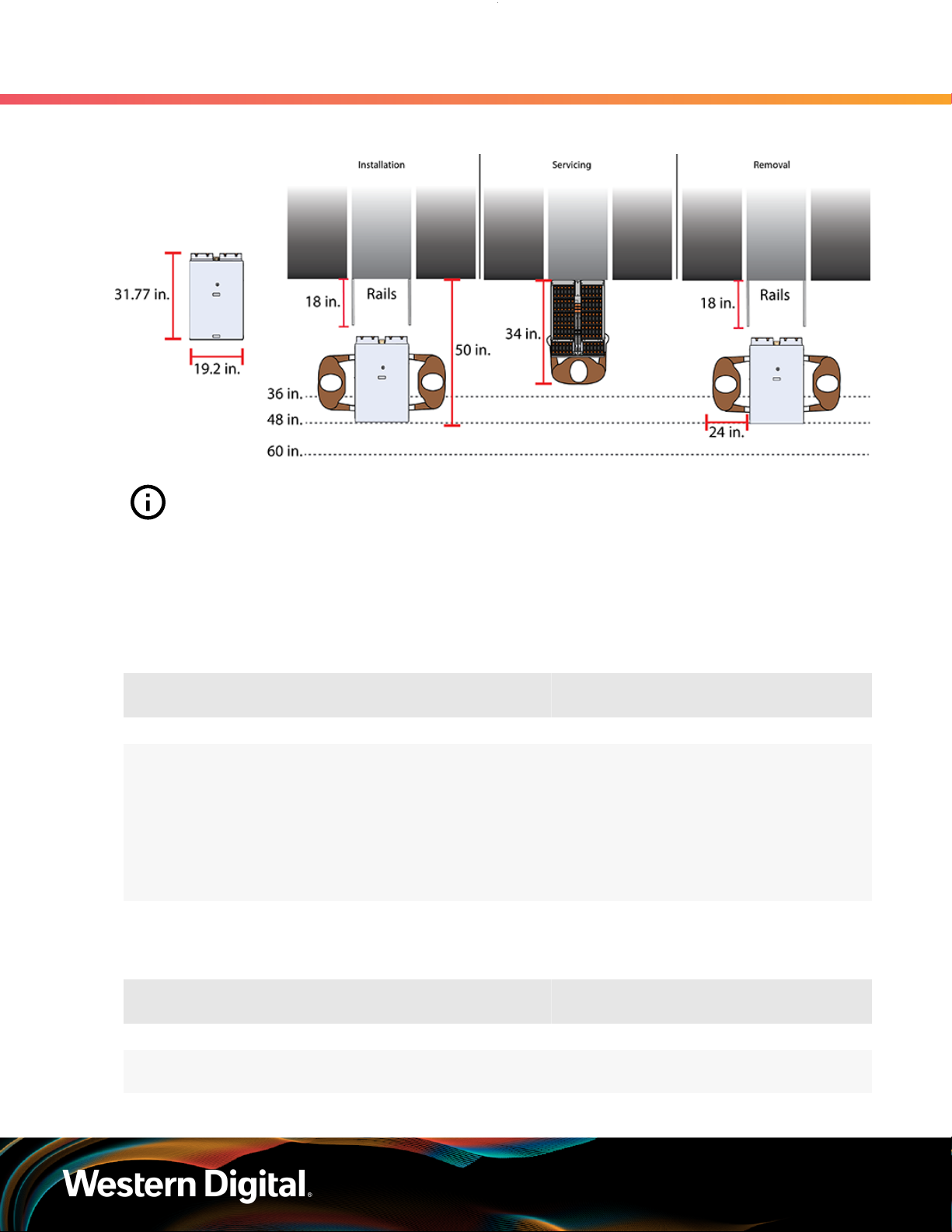
The following section provides specific information necessary to install, service, and remove the Ultrastar
Data60 . The installation of the Ultrastar Data60 requires two people and a space of 1270mm / 50in.
in front of the installation space. The servicing of the enclosure requires one person and a minimum of
863.6mm / 34in. of space in front of the installation space. The removal of the enclosure requires two
people, 914.4mm / 36in. of space in front of the installation space, and 24in. on either side of the enclosure
for two people to remove the enclosure.
Warning: The handles on the front of the chassis are not intended to be used to support the
weight of the Ultrastar Data60 . Lifting the unit by the chassis handles or trying to support the
unit on the handles can cause them to fail. This can cause serious damage to the unit or serious
bodily harm to those handling the unit. Always team lift the chassis by gripping the underside
of the unit, and never try to lift a chassis that is filled with drives.
450mm (17.72in.) with 465mm (18.31in.) ± 1.5mm
nominal hole spacing. See EIA-310 Rack Standard
16
User Guide
Figure 13: Installation, Servicing, and Removal
1. Overview
1.12 Ultrastar Data60 Rack Requirements
Attention: Do not install or remove the enclosure while it is populated with drives. The fully
populated enclosure exceeds the amount of weight that a team of two should lift.
1.12.1 Compatible Rack Hardware Configuration
The following table(s) list the approved rack hardware configurations for the Ultrastar Data60 :
Table 16: Compatible Hardware Configuration 1
Parameter Rack PDU (Vertical)
Vendor CRENLO/EMCOR Server Technology Server Technology Various
AS-160099-03
(Drawing
Number EMCOR
Part
Number
Quantity 1 2 2 Varies
526121 Rev 5)
412-0761-11_STV-4501
412-0761-20_STV-4502
412-0761-23_STV-4503
PDU Mounting
Bracket
KIT-MBVPT-1B
(one kit per PDU)
Additional Mounting
Bracket Hardware
4 x M6 x 16 Hex
Cap Screws
8 x M6 Fender
4 x M6 Hex Nut
with Nylon Lock
Washers
Table 17: Compatible Hardware Configuration 2
Parameter Rack PDU (Vertical)
Vendor AFCO/Legrand Server Technology Server Technology Various
Part
Number
Options:
412-0761-11_STV-4501
PDU Mounting
Bracket
KIT-MB-40 None
Additional Mounting
Bracket Hardware
17

User Guide
1. Overview
1.12 Ultrastar Data60 Rack Requirements
Parameter Rack PDU (Vertical)
42RU –
WEDIT605
45RU –
WEDIT604
48RU –
WEDIT603
51RU –
WEDIT606
Quantity 1 rack 2 1 N/A
412-0761-20_STV-4502
412-0761-23_STV-4503
PDU Mounting
Bracket
Additional Mounting
Bracket Hardware
Table 18: Compatible Hardware Configuration 3
Parameter Rack PDU (Vertical)
Vendor TRIPP LITE Server Technology Server Technology Various
Options:
SR42UBDP (Rack)
412-0761-11_STV-4501
412-0761-20_STV-4502
PDU Mounting
Bracket
KIT-MBVPT-1B None
Additional Mounting
Bracket Hardware
SREXTENDER
25U (Rack
Part
Number
Quantity 1 rack 2 1 N/A
Extension)
SREXTENDER
42U (Rack
Extension)
SREXTENDER
48U (Rack
Extension)
412-0761-23_STV-4503
Table 19: Compatible Hardware Configuration 4
Parameter Rack PDU (Vertical)
Vendor APC/Schneider Server Technology Server Technology Various
AR3300W
Part
Number
412-0761-11_STV-4501
412-0761-20_STV-4502
412-0761-23_STV-4503
PDU Mounting
Bracket
KIT-MBVPT-1B
(one kit per PDU)
Additional Mounting
Bracket Hardware
4 x M6 x 16 Hex
8 x M6 Fender
Cap Screws
Washers
4 x M6 Hex Nut
with Nylon Lock
18

User Guide
1. Overview
1.13 Power Requirements
Parameter Rack PDU (Vertical)
Quantity 1 rack 2 2 Varies
1.13 Power Requirements
The following table describes the A/C input power specification for the Ultrastar Data60 .
Table 20: AC Power Specifications
Alternating Current (AC) Power Supply (2 per enclosure)
Wattage (per power supply)
Voltage (per power supply) 200 - 240 VAC, auto-ranging, 50/60 Hz
Maximum inrush current (per power
supply)
PDU Mounting
Bracket
Power
3
Supply Rating: 80 PLUS Platinum rated
Max Power Consumption: ~1250W
Typical Power Consumption: ~1000W
AC line inrush current shall not exceed 40A
peak, for up to one-quarter of the AC cycle
after which, the input current should be no
more than the specified maximum input current.
Additional Mounting
Bracket Hardware
Caution: The Ultrastar Data60 can only be plugged into high line (220-240 VAC). If the unit is
plugged into low line (110-127 VAC), the PSU will report a "Critical" state when status pages
are queried using SES. In this case, the enclosure will power up, but the drives will not. The
enclosure will remain in low-power mode.
1.14 ESD
The enclosure is designed to dissipate all electrostatic discharge (ESD) to the chassis base. Ensure that
there is sufficient electrical and mechanical connection from the chassis base to the rack rails, and that the
rack itself is tied to earth ground. Precautions must be taken to ensure that the system is not exposed to
ESD while handling components or servicing the unit.
The unit must be grounded in accordance with all local/regional and national electrical codes.
1.15 Enclosure Cooling
3. Max and typical power consumption values represent the output power to the system. Input power will vary depending
on the PSU efficiency and load sharing between PSUs.
19

User Guide
The Ultrastar Data60 has an advanced thermal algorithm running within the logical enclosure services
process called the SEP that monitors all of the temperature sensors in the enclosure. The SEP makes
adjustments to the fan speeds based upon the thermal sensors. The fan algorithm takes into account the
component and the warning and critical threshold limits defaulted and managed by the SEP controller. If
any temperature sensor exceeds the temperature threshold configured in the SES pages, the fan speed
will increase to cool the enclosure. If the enclosure encounters low temperatures, the enclosure will reduce
fan speed in an attempt to conserve power and not over-cool the enclosure. This algorithm is agnostic
to effects of altitude and humidity. The algorithm works based on temperatures within the enclosure with
emphasis on reducing power consumption.
The rack that the Ultrastar Data60 is installed in must not restrict airflow to the enclosure. Racks with doors
should be tested to ensure they do not constrict airflow to the enclosure. If the enclosure reaches critical
temperature, it will go into low-power mode to avoid damage to the enclosure.
When the Ultrastar Data60 is extended out of the rack, the cover of the enclosure remains inside the
rack which exposes the drives. This feature allows for easier access to drives and simplifies maintenance
tasks related to internal components. However, there is a limit to the amount of time the enclosure can be
extended out of the rack before the enclosure will begin to overheat.
1. Overview
1.16 SAS Cabling
Attention: Limit the amount of time that the enclosure is extended out of the rack to only
what is necessary to exchange a component or perform regular maintenance and should be
limited to a maximum of 5 minutes total. Never extend the enclosure out for longer than 5
minutes to prevent overheating. Only extend the enclosure out of the rack as far as necessary
to service components. The enclosure is equipped with a sensor that will be tripped when
the enclosure's top cover has been opened resulting in the rear fans increasing to max speed.
In the event that a fan has failed, it must be replaced before any other CRUs and should be
removed from the enclosure within 30 seconds of removing the enclosure cover.
1.16 SAS Cabling
The Ultrastar Data60 can use passive cables up to 3m in length, or active cables up to 10m, for SAS
connections to the host. Active cables must be used for Ultrastar Data60 to Ultrastar Data60 daisy-chaining
connections. All approved passive and active SAS cables are listed in the following table.
Note: MegaRAID adapters do not support the use of active SAS cables. If your configuration
requires the use of MegaRAID adapters, passive cables must be used.
Table 21: Approved SAS Cables
Type Length Manufacturer Vendor Part Number
Active Optical
HD Mini-SAS to HD Mini-SAS
5. Listed FOHHB23P00xxx cables are compatible, beginning with FW 2052-003.
4. Active cables can be used for both direct (host-to-enclosure) and daisy-chain (enclosure-to-enclosure) connections.
4
3m
4m Amphenol ICC (FCI) FOHHB23P00004
Amphenol ICC (FCI) FOHHB23P00003
Molex 106415-2103
5
20

User Guide
1. Overview
1.16 SAS Cabling
Type Length Manufacturer Vendor Part Number
Amphenol ICC (FCI) FOHHB23P000055m
Molex 106415-2105
6m Amphenol ICC (FCI) FOHHB23P00006
10m Molex 106415-2110
Passive
HD Mini-SAS to HD Mini-SAS
Active Cables
When daisy-chaining multiple Ultrastar Data60 enclosures together, active cables must be used between
enclosures for improved signal integrity.
Passive Cabling
As a best practice, Western Digital requires connecting the cables to every other SAS connector port when
connecting more than one host per IOM. Please refer to Table 22: Recommended IOM Port Connection
Order (page 21) for port connection ordering required for IOMA and IOMB:
6
1m Amphenol ICC (FCI) 10112041-2010LF
2m
3m
Amphenol ICC (FCI) 601760006
CS Electronics 12G-HD-4444/2M
Data Storage Cables (DSC) C5555-2M
The Mate Company (TMC) C5555-2M
10112041-2020LFAmphenol ICC (FCI)
10117949-2020LF
Molex 1110751002
Amphenol ICC (FCI) 601760008
CS Electronics 12G-HD-4444/3M
10112041-2030LFAmphenol ICC (FCI)
10117949-4030LF
Molex 1110751003
6. Passive cables should only be used for direct (host-to-enclosure) connections.
21

User Guide
Table 22: Recommended IOM Port Connection Order
IOM 1st Host 2nd Host 3rd Host 4th Host 5th Host 6th Host
A A6 A4 A2 A5 A3 A1
B B1 B3 B5 B2 B4 B6
Edge Buffering
Edge buffering is an enclosure feature that increases the overall performance when a 6Gb/s target is
connected. With edge buffering disabled, primitives that can be deleted from the initiator are added to
slow the effective logical rate to the slowest target device connected between the initiator and the target
device. With edge buffering enabled, the expanders buffer data from slower 6Gb/s targets to utilize the
12Gb/s link from the expander to the initiator in a more efficient manner.
1.17 Supported SKUs
The following table lists the versions of this HGST product that are supported by this document.
Table 23: List of Supported SKUs
1. Overview
1.17 Supported SKUs
1ES1157 1ES1158 1ES1159 1ES1160 1ES1161 1ES1162
1ES1163 1ES1164 1ES1234 1ES1235 1ES1236 1ES1237
1ES1238 1ES1239 1ES1240 1ES1241 1ES0347 1ES0348
1ES0349 1ES0350 1ES0351 1ES0352 1ES0353 1ES0354
1ES0355 1ES0356 1ES0357 1ES0358 1ES0359 1ES0360
1ES0361 1ES0362 1ES0363 1ES0364 1ES0365 1ES0366
1ES0367 1ES0368 1ES0369 1ES0370 1ES1461 1ES1462
1ES1463 1ES1464 1ES1465 1ES1466 1ES1467
1.18 List of Compatible Drives
HDD with 3.5-inch Drive Carrier
Table 24: Western Digital Ultrastar DC HC310
Drive Type Interface
Ultrastar DC HC310
w/ 3.5 in. drive carrier
HDD SATA 6Gb/s 512e SE 6TB 1EX1189
SKUs
Sector
Size
Encryption Volume Part Number
Ultrastar DC HC310
w/ 3.5 in. drive carrier
Ultrastar DC HC310
w/ 3.5 in. drive carrier
Ultrastar DC HC310 HDD SATA 6Gb/s 4Kn TCG 6TB 1EX1186
HDD SATA 6Gb/s 512e TCG 6TB 1EX1188
HDD SATA 6Gb/s 4Kn SE 6TB 1EX1187
22

User Guide
1. Overview
1.18 List of Compatible Drives
Drive Type Interface
w/ 3.5 in. drive carrier
Ultrastar DC HC310
w/ 3.5 in. drive carrier
Ultrastar DC HC310
w/ 3.5 in. drive carrier
Ultrastar DC HC310
w/ 3.5 in. drive carrier
Ultrastar DC HC310
w/ 3.5 in. drive carrier
Ultrastar DC HC310
w/ 3.5 in. drive carrier
Ultrastar DC HC310
w/ 3.5 in. drive carrier
HDD SAS 12Gb/s 512e SE 6TB 1EX1185
HDD SAS 12Gb/s 512e TCG 6TB 1EX1184
HDD SAS 12Gb/s 512e TCG-FIPS 6TB 1EX1853
HDD SAS 12Gb/s 4Kn SE 6TB 1EX1183
HDD SAS 12Gb/s 4Kn TCG 6TB 1EX1182
HDD SAS 12Gb/s 4Kn TCG-FIPS 6TB 1EX1852
Table 25: Western Digital Ultrastar DC HC320
Drive Type Interface
Ultrastar DC HC320
w/ 3.5 in. drive carrier
HDD SATA 6Gb/s 512e SE 8TB 1EX1227
Sector
Size
Sector
Size
Encryption Volume Part Number
Encryption Volume Part Number
Ultrastar DC HC320
w/ 3.5 in. drive carrier
Ultrastar DC HC320
w/ 3.5 in. drive carrier
Ultrastar DC HC320
w/ 3.5 in. drive carrier
Ultrastar DC HC320
w/ 3.5 in. drive carrier
Ultrastar DC HC320
w/ 3.5 in. drive carrier
Ultrastar DC HC320
w/ 3.5 in. drive carrier
Ultrastar DC HC320
w/ 3.5 in. drive carrier
Ultrastar DC HC320
w/ 3.5 in. drive carrier
Ultrastar DC HC320
w/ 3.5 in. drive carrier
HDD SATA 6Gb/s 512e SED 8TB 1EX1226
HDD SATA 6Gb/s 4Kn SE 8TB 1EX1225
HDD SATA 6Gb/s 4Kn TCG 8TB 1EX1224
HDD SAS 12Gb/s 512e SE 8TB 1EX1223
HDD SAS 12Gb/s 512e TCG 8TB 1EX1222
HDD SAS 12Gb/s 512e TCG-FIPS 8TB 1EX1343
HDD SAS 12Gb/s 4Kn SE 8TB 1EX1221
HDD SAS 12Gb/s 4Kn TCG 8TB 1EX1220
HDD SAS 12Gb/s 4Kn TCG-FIPS 8TB 1EX1342
23

User Guide
Table 26: Western Digital Ultrastar DC HC330
1. Overview
1.18 List of Compatible Drives
Drive Type Interface
Ultrastar DC HC330
w/ 3.5 in. drive carrier
Ultrastar DC HC330
w/ 3.5 in. drive carrier
Ultrastar DC HC330
w/ 3.5 in. drive carrier
Ultrastar DC HC330
w/ 3.5 in. drive carrier
Ultrastar DC HC330
w/ 3.5 in. drive carrier
Ultrastar DC HC330
w/ 3.5 in. drive carrier
Ultrastar DC HC330
w/ 3.5 in. drive carrier
Ultrastar DC HC330
w/ 3.5 in. drive carrier
Ultrastar DC HC330
w/ 3.5 in. drive carrier
Sector
Size
HDD SATA 6Gb/s 512e SE 10TB 1EX2440
HDD SATA 6Gb/s 512e SED 10TB 1EX2441
HDD SATA 6Gb/s 4Kn SE 10TB 1EX2438
HDD SATA 6Gb/s 4Kn SED 10TB 1EX2439
HDD SAS 12Gb/s 512e SE 10TB 1EX2435
HDD SAS 12Gb/s 512e TCG 10TB 1EX2436
HDD SAS 12Gb/s 512e TCG-FIPS 10TB 1EX2437
HDD SAS 12Gb/s 4Kn TCG 10TB 1EX2433
HDD SAS 12Gb/s 4Kn TCG-FIPS 10TB 1EX2434
Encryption Volume Part Number
Table 27: Western Digital Ultrastar DC HC510
Drive Type Interface
Ultrastar DC HC510
w/ 3.5 in. drive carrier
Ultrastar DC HC510
w/ 3.5 in. drive carrier
Ultrastar DC HC510
w/ 3.5 in. drive carrier
Ultrastar DC HC510
w/ 3.5 in. drive carrier
Ultrastar DC HC510
w/ 3.5 in. drive carrier
Ultrastar DC HC510
w/ 3.5 in. drive carrier
Ultrastar DC HC510
w/ 3.5 in. drive carrier
Ultrastar DC HC510
w/ 3.5 in. drive carrier
Ultrastar DC HC510 HDD SAS 12Gb/s 512e TCG 10TB 1EX0486
HDD SATA 6Gb/s 512e SE 10TB 1EX0499
HDD SATA 6Gb/s 512e ISE 10TB 1EX0497
HDD SATA 6Gb/s 512e SED 10TB 1EX0498
HDD SATA 6Gb/s 4Kn SE 10TB 1EX0496
HDD SATA 6Gb/s 4Kn ISE 10TB 1EX0494
HDD SATA 6Gb/s 4Kn SED 10TB 1EX0495
HDD SAS 12Gb/s 512e SE 10TB 1EX0487
HDD SAS 12Gb/s 512e ISE 10TB 1EX0485
Sector
Size
Encryption Volume Part Number
24

User Guide
1. Overview
1.18 List of Compatible Drives
Drive Type Interface
w/ 3.5 in. drive carrier
Ultrastar DC HC510
w/ 3.5 in. drive carrier
Ultrastar DC HC510
w/ 3.5 in. drive carrier
Ultrastar DC HC510
w/ 3.5 in. drive carrier
Ultrastar DC HC510
w/ 3.5 in. drive carrier
Ultrastar DC HC510
w/ 3.5 in. drive carrier
HDD SAS 12Gb/s 512e TCG-FIPS 10TB 1EX1341
HDD SAS 12Gb/s 4Kn SE 10TB 1EX0484
HDD SAS 12Gb/s 4Kn ISE 10TB 1EX0482
HDD SAS 12Gb/s 4Kn TCG 10TB 1EX0483
HDD SAS 12Gb/s 4Kn TCG-FIPS 10TB 1EX1340
Table 28: Western Digital Ultrastar DC HC520
Drive Type Interface
Ultrastar DC HC520
w/ 3.5 in. drive carrier
Ultrastar DC HC520
w/ 3.5 in. drive carrier
HDD SATA 6Gb/s 512e SE 12TB 1EX1015
HDD SATA 6Gb/s 512e ISE 12TB 1EX1013
Sector
Size
Sector
Size
Encryption Volume Part Number
Encryption Volume Part Number
Ultrastar DC HC520
w/ 3.5 in. drive carrier
Ultrastar DC HC520
w/ 3.5 in. drive carrier
Ultrastar DC HC520
w/ 3.5 in. drive carrier
Ultrastar DC HC520
w/ 3.5 in. drive carrier
Ultrastar DC HC520
w/ 3.5 in. drive carrier
Ultrastar DC HC520
w/ 3.5 in. drive carrier
Ultrastar DC HC520
w/ 3.5 in. drive carrier
Ultrastar DC HC520
w/ 3.5 in. drive carrier
Ultrastar DC HC520
w/ 3.5 in. drive carrier
Ultrastar DC HC520
w/ 3.5 in. drive carrier
HDD SATA 6Gb/s 512e SED 12TB 1EX1014
HDD SATA 6Gb/s 4Kn SE 12TB 1EX1012
HDD SATA 6Gb/s 4Kn ISE 12TB 1EX1010
HDD SATA 6Gb/s 4Kn SED 12TB 1EX1011
HDD SAS 12Gb/s 512e SE 12TB 1EX1009
HDD SAS 12Gb/s 512e ISE 12TB 1EX1007
HDD SAS 12Gb/s 512e TCG 12TB 1EX1008
HDD SAS 12Gb/s 512e TCG-FIPS 12TB 1EX1338
HDD SAS 12Gb/s 4Kn SE 12TB 1EX1006
HDD SAS 12Gb/s 4Kn ISE 12TB 1EX1004
Ultrastar DC HC520
w/ 3.5 in. drive carrier
HDD SAS 12Gb/s 4Kn TCG 12TB 1EX1005
25

User Guide
1. Overview
1.18 List of Compatible Drives
Drive Type Interface
Ultrastar DC HC520
w/ 3.5 in. drive carrier
HDD SAS 12Gb/s 4Kn TCG-FIPS 12TB 1EX1339
Table 29: Western Digital Ultrastar DC HC530
Drive Type Interface
Ultrastar DC HC530
w/ 3.5 in. drive carrier
Ultrastar DC HC530
w/ 3.5 in. drive carrier
Ultrastar DC HC530
w/ 3.5 in. drive carrier
Ultrastar DC HC530
w/ 3.5 in. drive carrier
Ultrastar DC HC530
w/ 3.5 in. drive carrier
Ultrastar DC HC530
w/ 3.5 in. drive carrier
HDD SATA 6Gb/s 512e SE 14TB 1EX1793
HDD SATA 6Gb/s 512e SED 14TB 1EX1794
HDD SATA 6Gb/s 4Kn SE 14TB 1EX1790
HDD SAS 12Gb/s 512e SE 14TB 1EX1791
HDD SAS 12Gb/s 512e ISE 14TB 1EX1583
HDD SAS 12Gb/s 512e TCG 14TB 1EX1792
Sector
Size
Sector
Size
Encryption Volume Part Number
Encryption Volume Part Number
Ultrastar DC HC530
w/ 3.5 in. drive carrier
Ultrastar DC HC530
w/ 3.5 in. drive carrier
Ultrastar DC HC530
w/ 3.5 in. drive carrier
Ultrastar DC HC530
w/ 3.5 in. drive carrier
HDD SAS 12Gb/s 512e TCG-FIPS 14TB 1EX1855
HDD SAS 12Gb/s 4Kn SE 14TB 1EX1788
HDD SAS 12Gb/s 4Kn TCG 14TB 1EX1789
HDD SAS 12Gb/s 4Kn TCG-FIPS 14TB 1EX1854
Table 30: Western Digital Ultrastar DC HC550
Drive Type Interface
Ultrastar DC HC550
w/ 3.5 in. drive carrier
Ultrastar DC HC550
w/ 3.5 in. drive carrier
Ultrastar DC HC550
w/ 3.5 in. drive carrier
Ultrastar DC HC550
w/ 3.5 in. drive carrier
HDD SATA 6Gb/s 512e SE 16TB 1EX2476
HDD SATA 6Gb/s 512e SED 16TB 1EX2477
HDD SAS 12Gb/s 512e SE 16TB 1EX2473
HDD SAS 12Gb/s 512e TCG 16TB 1EX2474
Sector
Size
Encryption Volume Part Number
Ultrastar DC HC550
w/ 3.5 in. drive carrier
Ultrastar DC HC550 HDD SATA 6Gb/s 512e SE 18TB 1EX2481
HDD SAS 12Gb/s 512e TCG-FIPS 16TB 1EX2475
26

User Guide
1. Overview
1.18 List of Compatible Drives
Drive Type Interface
w/ 3.5 in. drive carrier
Ultrastar DC HC550
w/ 3.5 in. drive carrier
Ultrastar DC HC550
w/ 3.5 in. drive carrier
Ultrastar DC HC550
w/ 3.5 in. drive carrier
Ultrastar DC HC550
w/ 3.5 in. drive carrier
HDD SATA 6Gb/s 512e SED 18TB 1EX2482
HDD SAS 12Gb/s 512e SE 18TB 1EX2478
HDD SAS 12Gb/s 512e TCG 18TB 1EX2479
HDD SAS 12Gb/s 512e TCG-FIPS 18TB 1EX2480
SSD with 2.5-inch Drive Carrier
Table 31: Western Digital Ultrastar SS300
Drive Type Interface Drive Writes Encryption Volume
Ultrastar SS300
w/ 2.5 in. drive carrier
Ultrastar SS300
w/ 2.5 in. drive carrier
SSD SAS 12Gb/s RI-3DW/D SE 400GB
SSD SAS 12Gb/s RI-3DW/D ISE 400GB
Sector
Size
Encryption Volume Part Number
Part
Number
No longer
available
No longer
available
Ultrastar SS300
w/ 2.5 in. drive carrier
Ultrastar SS300
w/ 2.5 in. drive carrier
Ultrastar SS300
w/ 2.5 in. drive carrier
Ultrastar SS300
w/ 2.5 in. drive carrier
Ultrastar SS300
w/ 2.5 in. drive carrier
Ultrastar SS300
w/ 2.5 in. drive carrier
Ultrastar SS300
w/ 2.5 in. drive carrier
Ultrastar SS300
w/ 2.5 in. drive carrier
Ultrastar SS300
w/ 2.5 in. drive carrier
Ultrastar SS300
w/ 2.5 in. drive carrier
SSD SAS 12Gb/s RI-3DW/D TCG 400GB
SSD SAS 12Gb/s RI-3DW/D TCG-FIPS 400GB
SSD SAS 12Gb/s ME-10DW/D SE 400GB
SSD SAS 12Gb/s ME-10DW/D ISE 400GB
SSD SAS 12Gb/s ME-10DW/D TCG 400GB
SSD SAS 12Gb/s ME-10DW/D TCG-FIPS 400GB
SSD SAS 12Gb/s RI-3DW/D SE 800GB
SSD SAS 12Gb/s RI-3DW/D ISE 800GB
SSD SAS 12Gb/s RI-3DW/D TCG 800GB
SSD SAS 12Gb/s RI-3DW/D TCG-FIPS 800GB
No longer
available
No longer
available
No longer
available
No longer
available
No longer
available
No longer
available
No longer
available
No longer
available
No longer
available
No longer
available
Ultrastar SS300
w/ 2.5 in. drive carrier
SSD SAS 12Gb/s ME-10DW/D SE 800GB
No longer
available
27

User Guide
1. Overview
1.18 List of Compatible Drives
Drive Type Interface Drive Writes Encryption Volume
Ultrastar SS300
w/ 2.5 in. drive carrier
Ultrastar SS300
w/ 2.5 in. drive carrier
Ultrastar SS300
w/ 2.5 in. drive carrier
Ultrastar SS300
w/ 2.5 in. drive carrier
Ultrastar SS300
w/ 2.5 in. drive carrier
Ultrastar SS300
w/ 2.5 in. drive carrier
SSD SAS 12Gb/s ME-10DW/D ISE 800GB
SSD SAS 12Gb/s ME-10DW/D TCG 800GB
SSD SAS 12Gb/s ME-10DW/D TCG-FIPS 800GB
SSD SAS 12Gb/s RI-3DW/D ISE 1.6TB
SSD SAS 12Gb/s RI-3DW/D TCG-FIPS 1.6TB
SSD SAS 12Gb/s ME-10DW/D TCG-FIPS 1.6TB
SSD with 3.5-inch to 2.5-inch Drive Carrier
Table 32: Western Digital Ultrastar SS200
Drive Type Interface Drive Writes Encryption Volume
Ultrastar SS200
w/ 3.5 in. to 2.5 in. drive carrier
SSD SAS 12Gb/s RI-3DW/D SE 400GB
Part
Number
No longer
available
No longer
available
No longer
available
No longer
available
No longer
available
No longer
available
Part
Number
No longer
available
Ultrastar SS200
w/ 3.5 in. to 2.5 in. drive carrier
Ultrastar SS200
w/ 3.5 in. to 2.5 in. drive carrier
Ultrastar SS200
w/ 3.5 in. to 2.5 in. drive carrier
Ultrastar SS200
w/ 3.5 in. to 2.5 in. drive carrier
Ultrastar SS200
w/ 3.5 in. to 2.5 in. drive carrier
Ultrastar SS200
w/ 3.5 in. to 2.5 in. drive carrier
Ultrastar SS200
w/ 3.5 in. to 2.5 in. drive carrier
Ultrastar SS200
w/ 3.5 in. to 2.5 in. drive carrier
Ultrastar SS200
w/ 3.5 in. to 2.5 in. drive carrier
Ultrastar SS200
w/ 3.5 in. to 2.5 in. drive carrier
SSD SAS 12Gb/s RI-3DW/D ISE 400GB
SSD SAS 12Gb/s RI-3DW/D TCG 400GB
SSD SAS 12Gb/s RI-3DW/D TCG-FIPS 400GB
SSD SAS 12Gb/s RI-1DW/D TCG 480GB
SSD SAS 12Gb/s RI-3DW/D SE 800GB
SSD SAS 12Gb/s RI-3DW/D ISE 800GB
SSD SAS 12Gb/s RI-3DW/D TCG 800GB
SSD SAS 12Gb/s RI-1DW/D TCG 960GB
SSD SAS 12Gb/s RI-3DW/D SE 1.6TB
SSD SAS 12Gb/s RI-3DW/D ISE 1.6TB
No longer
available
No longer
available
No longer
available
No longer
available
No longer
available
No longer
available
No longer
available
No longer
available
No longer
available
No longer
available
28

User Guide
1. Overview
1.18 List of Compatible Drives
Drive Type Interface Drive Writes Encryption Volume
Ultrastar SS200
w/ 3.5 in. to 2.5 in. drive carrier
Ultrastar SS200
w/ 3.5 in. to 2.5 in. drive carrier
Ultrastar SS200
w/ 3.5 in. to 2.5 in. drive carrier
Ultrastar SS200
w/ 3.5 in. to 2.5 in. drive carrier
Ultrastar SS200
w/ 3.5 in. to 2.5 in. drive carrier
SSD SAS 12Gb/s RI-3DW/D TCG 1.6TB
SSD SAS 12Gb/s RI-1DW/D TCG 1.92TB
SSD SAS 12Gb/s RI-3DW/D ISE 3.2TB
SSD SAS 12Gb/s RI-1DW/D ISE 3.84TB
SSD SAS 12Gb/s RI-1DW/D SE 7.68TB
Table 33: Western Digital Ultrastar SS300
Drive Type Interface Drive Writes Encryption Volume
Ultrastar SS300
w/ 3.5 in. to 2.5 in. drive carrier
Ultrastar SS300
w/ 3.5 in. to 2.5 in. drive carrier
SSD SAS 12Gb/s RI-3DW/D SE 400GB
SSD SAS 12Gb/s RI-3DW/D ISE 400GB
Part
Number
No longer
available
No longer
available
No longer
available
No longer
available
No longer
available
Part
Number
No longer
available
No longer
available
Ultrastar SS300
w/ 3.5 in. to 2.5 in. drive carrier
Ultrastar SS300
w/ 3.5 in. to 2.5 in. drive carrier
Ultrastar SS300
w/ 3.5 in. to 2.5 in. drive carrier
Ultrastar SS300
w/ 3.5 in. to 2.5 in. drive carrier
Ultrastar SS300
w/ 3.5 in. to 2.5 in. drive carrier
Ultrastar SS300
w/ 3.5 in. to 2.5 in. drive carrier
Ultrastar SS300
w/ 3.5 in. to 2.5 in. drive carrier
Ultrastar SS300
w/ 3.5 in. to 2.5 in. drive carrier
Ultrastar SS300
w/ 3.5 in. to 2.5 in. drive carrier
Ultrastar SS300
w/ 3.5 in. to 2.5 in. drive carrier
SSD SAS 12Gb/s RI-3DW/D TCG 400GB
SSD SAS 12Gb/s ME-10DW/D SE 400GB
SSD SAS 12Gb/s ME-10DW/D ISE 400GB
SSD SAS 12Gb/s ME-10DW/D TCG 400GB
SSD SAS 12Gb/s ME-10DW/D TCG-FIPS 400GB
SSD SAS 12Gb/s RI-3DW/D SE 800GB
SSD SAS 12Gb/s RI-3DW/D ISE 800GB
SSD SAS 12Gb/s RI-3DW/D TCG 800GB
SSD SAS 12Gb/s RI-3DW/D TCG-FIPS 800GB
SSD SAS 12Gb/s ME-10DW/D SE 800GB
No longer
available
No longer
available
No longer
available
No longer
available
No longer
available
No longer
available
No longer
available
No longer
available
No longer
available
No longer
available
Ultrastar SS300
w/ 3.5 in. to 2.5 in. drive carrier
SSD SAS 12Gb/s ME-10DW/D ISE 800GB
No longer
available
29

User Guide
1. Overview
1.18 List of Compatible Drives
Drive Type Interface Drive Writes Encryption Volume
Ultrastar SS300
w/ 3.5 in. to 2.5 in. drive carrier
Ultrastar SS300
w/ 3.5 in. to 2.5 in. drive carrier
Ultrastar SS300
w/ 3.5 in. to 2.5 in. drive carrier
Ultrastar SS300
w/ 3.5 in. to 2.5 in. drive carrier
Ultrastar SS300
w/ 3.5 in. to 2.5 in. drive carrier
Ultrastar SS300
w/ 3.5 in. to 2.5 in. drive carrier
Ultrastar SS300
w/ 3.5 in. to 2.5 in. drive carrier
Ultrastar SS300
w/ 3.5 in. to 2.5 in. drive carrier
Ultrastar SS300
w/ 3.5 in. to 2.5 in. drive carrier
SSD SAS 12Gb/s ME-10DW/D TCG 800GB
SSD SAS 12Gb/s ME-10DW/D TCG-FIPS 800GB
SSD SAS 12Gb/s RI-3DW/D SE 1.6TB
SSD SAS 12Gb/s RI-3DW/D ISE 1.6TB
SSD SAS 12Gb/s RI-3DW/D TCG 1.6TB
SSD SAS 12Gb/s RI-3DW/D TCG-FIPS 1.6TB
SSD SAS 12Gb/s RI-10DW/D SE 1.6TB
SSD SAS 12Gb/s RI-10DW/D ISE 1.6TB
SSD SAS 12Gb/s RI-10DW/D TCG 1.6TB
Part
Number
No longer
available
No longer
available
No longer
available
No longer
available
No longer
available
No longer
available
No longer
available
No longer
available
No longer
available
Ultrastar SS300
w/ 3.5 in. to 2.5 in. drive carrier
Ultrastar SS300
w/ 3.5 in. to 2.5 in. drive carrier
Ultrastar SS300
w/ 3.5 in. to 2.5 in. drive carrier
SSD SAS 12Gb/s ME-10DW/D TCG-FIPS 1.6TB
SSD SAS 12Gb/s RI-3DW/D SE 3.2TB
SSD SAS 12Gb/s RI-3DW/D ISE 3.2TB
Table 34: Western Digital Ultrastar SS530
Drive Type Interface Drive Writes Encryption Volume
Ultrastar SS530
w/ 3.5 in. to 2.5 in. drive carrier
Ultrastar SS530
w/ 3.5 in. to 2.5 in. drive carrier
Ultrastar SS530
w/ 3.5 in. to 2.5 in. drive carrier
Ultrastar SS530
w/ 3.5 in. to 2.5 in. drive carrier
Ultrastar SS530
w/ 3.5 in. to 2.5 in. drive carrier
SSD SAS 12Gb/s RI-3DW/D SE 400GB 1EX2020
SSD SAS 12Gb/s RI-3DW/D ISE 400GB 1EX2021
SSD SAS 12Gb/s RI-3DW/D TCG 400GB 1EX2087
SSD SAS 12Gb/s ME-10DW/D SE 400GB 1EX2012
SSD SAS 12Gb/s ME-10DW/D ISE 400GB 1EX2013
No longer
available
No longer
available
No longer
available
Part
Number
Ultrastar SS530
w/ 3.5 in. to 2.5 in. drive carrier
Ultrastar SS530 SSD SAS 12Gb/s RI-1DW/D SE 480GB 1EX2030
SSD SAS 12Gb/s ME-10DW/D TCG 400GB 1EX2083
30

User Guide
1. Overview
1.18 List of Compatible Drives
Drive Type Interface Drive Writes Encryption Volume
w/ 3.5 in. to 2.5 in. drive carrier
Ultrastar SS530
w/ 3.5 in. to 2.5 in. drive carrier
Ultrastar SS530
w/ 3.5 in. to 2.5 in. drive carrier
Ultrastar SS530
w/ 3.5 in. to 2.5 in. drive carrier
Ultrastar SS530
w/ 3.5 in. to 2.5 in. drive carrier
Ultrastar SS530
w/ 3.5 in. to 2.5 in. drive carrier
Ultrastar SS530
w/ 3.5 in. to 2.5 in. drive carrier
Ultrastar SS530
w/ 3.5 in. to 2.5 in. drive carrier
Ultrastar SS530
w/ 3.5 in. to 2.5 in. drive carrier
Ultrastar SS530
w/ 3.5 in. to 2.5 in. drive carrier
Part
Number
SSD SAS 12Gb/s RI-1DW/D ISE 480GB 1EX2031
SSD SAS 12Gb/s RI-1DW/D TCG 480GB 1EX2092
SSD SAS 12Gb/s RI-3DW/D SE 800GB 1EX2022
SSD SAS 12Gb/s RI-3DW/D ISE 800GB 1EX2023
SSD SAS 12Gb/s RI-3DW/D TCG 800GB 1EX2088
SSD SAS 12Gb/s ME-10DW/D SE 800GB 1EX2014
SSD SAS 12Gb/s ME-10DW/D ISE 800GB 1EX2015
SSD SAS 12Gb/s ME-10DW/D TCG 800GB 1EX2084
SSD SAS 12Gb/s RI-1DW/D SE 960GB 1EX2032
Ultrastar SS530
w/ 3.5 in. to 2.5 in. drive carrier
Ultrastar SS530
w/ 3.5 in. to 2.5 in. drive carrier
Ultrastar SS530
w/ 3.5 in. to 2.5 in. drive carrier
Ultrastar SS530
w/ 3.5 in. to 2.5 in. drive carrier
Ultrastar SS530
w/ 3.5 in. to 2.5 in. drive carrier
Ultrastar SS530
w/ 3.5 in. to 2.5 in. drive carrier
Ultrastar SS530
w/ 3.5 in. to 2.5 in. drive carrier
Ultrastar SS530
w/ 3.5 in. to 2.5 in. drive carrier
Ultrastar SS530
w/ 3.5 in. to 2.5 in. drive carrier
Ultrastar SS530
w/ 3.5 in. to 2.5 in. drive carrier
SSD SAS 12Gb/s RI-1DW/D ISE 960GB 1EX2033
SSD SAS 12Gb/s RI-1DW/D TCG 960GB 1EX2093
SSD SAS 12Gb/s RI-3DW/D SE 1.6TB 1EX2024
SSD SAS 12Gb/s RI-3DW/D ISE 1.6TB 1EX2025
SSD SAS 12Gb/s RI-3DW/D TCG 1.6TB 1EX2089
SSD SAS 12Gb/s ME-10DW/D SE 1.6TB 1EX2016
SSD SAS 12Gb/s ME-10DW/D ISE 1.6TB 1EX2017
SSD SAS 12Gb/s ME-10DW/D TCG 1.6TB 1EX2085
SSD SAS 12Gb/s RI-1DW/D SE 1.92TB 1EX2034
SSD SAS 12Gb/s RI-1DW/D ISE 1.92TB 1EX2035
Ultrastar SS530
w/ 3.5 in. to 2.5 in. drive carrier
SSD SAS 12Gb/s RI-1DW/D TCG 1.92TB 1EX2094
31

User Guide
1. Overview
1.18 List of Compatible Drives
Drive Type Interface Drive Writes Encryption Volume
Ultrastar SS530
w/ 3.5 in. to 2.5 in. drive carrier
Ultrastar SS530
w/ 3.5 in. to 2.5 in. drive carrier
Ultrastar SS530
w/ 3.5 in. to 2.5 in. drive carrier
Ultrastar SS530
w/ 3.5 in. to 2.5 in. drive carrier
Ultrastar SS530
w/ 3.5 in. to 2.5 in. drive carrier
Ultrastar SS530
w/ 3.5 in. to 2.5 in. drive carrier
Ultrastar SS530
w/ 3.5 in. to 2.5 in. drive carrier
Ultrastar SS530
w/ 3.5 in. to 2.5 in. drive carrier
Ultrastar SS530
w/ 3.5 in. to 2.5 in. drive carrier
Part
Number
SSD SAS 12Gb/s RI-3DW/D SE 3.2TB 1EX2026
SSD SAS 12Gb/s RI-3DW/D ISE 3.2TB 1EX2027
SSD SAS 12Gb/s RI-3DW/D TCG 3.2TB 1EX2090
SSD SAS 12Gb/s ME-10DW/D SE 3.2TB 1EX2018
SSD SAS 12Gb/s ME-10DW/D ISE 3.2TB 1EX2019
SSD SAS 12Gb/s ME-10DW/D TCG 3.2TB 1EX2086
SSD SAS 12Gb/s RI-1DW/D SE 3.84TB 1EX2036
SSD SAS 12Gb/s RI-1DW/D ISE 3.84TB 1EX2037
SSD SAS 12Gb/s RI-1DW/D TCG 3.84TB 1EX2095
Ultrastar SS530
w/ 3.5 in. to 2.5 in. drive carrier
Ultrastar SS530
w/ 3.5 in. to 2.5 in. drive carrier
Ultrastar SS530
w/ 3.5 in. to 2.5 in. drive carrier
Ultrastar SS530
w/ 3.5 in. to 2.5 in. drive carrier
Ultrastar SS530
w/ 3.5 in. to 2.5 in. drive carrier
Ultrastar SS530
w/ 3.5 in. to 2.5 in. drive carrier
Ultrastar SS530
w/ 3.5 in. to 2.5 in. drive carrier
Ultrastar SS530
w/ 3.5 in. to 2.5 in. drive carrier
Ultrastar SS530
w/ 3.5 in. to 2.5 in. drive carrier
SSD SAS 12Gb/s RI-3DW/D SE 6.4TB 1EX2028
SSD SAS 12Gb/s RI-3DW/D ISE 6.4TB 1EX2029
SSD SAS 12Gb/s RI-3DW/D TCG 6.4TB 1EX2091
SSD SAS 12Gb/s RI-1DW/D SE 7.68TB 1EX2038
SSD SAS 12Gb/s RI-1DW/D ISE 7.68TB 1EX2039
SSD SAS 12Gb/s RI-1DW/D TCG 7.68TB 1EX2096
SSD SAS 12Gb/s RI-1DW/D SE 15.36TB 1EX2040
SSD SAS 12Gb/s RI-1DW/D ISE 15.36TB 1EX2041
SSD SAS 12Gb/s RI-1DW/D TCG 15.36TB 1EX2097
32

User Guide
Table 35: Western Digital Ultrastar SA620
1. Overview
1.18 List of Compatible Drives
Drive Type Interface Drive Writes Encryption Volume
Ultrastar SA620
w/ 3.5 in. to 2.5 in. drive carrier
Ultrastar SA620
w/ 3.5 in. to 2.5 in. drive carrier
Ultrastar SA620
w/ 3.5 in. to 2.5 in. drive carrier
Ultrastar SA620
w/ 3.5 in. to 2.5 in. drive carrier
Ultrastar SA620
w/ 3.5 in. to 2.5 in. drive carrier
Ultrastar SA620
w/ 3.5 in. to 2.5 in. drive carrier
Ultrastar SA620
w/ 3.5 in. to 2.5 in. drive carrier
Ultrastar SA620
w/ 3.5 in. to 2.5 in. drive carrier
Ultrastar SA620
w/ 3.5 in. to 2.5 in. drive carrier
SSD SATA 6Gb/s RI-1.8DW/D SE 400GB
SSD SATA 6Gb/s RI-1.8DW/D ISE 400GB
SSD SATA 6Gb/s RI-0.6DW/D SE 480GB
SSD SATA 6Gb/s RI-0.6DW/D ISE 480GB
SSD SATA 6Gb/s RI-1.8DW/D SE 800GB
SSD SATA 6Gb/s RI-1.8DW/D ISE 800GB
SSD SATA 6Gb/s RI-0.6DW/D SE 960GB
SSD SATA 6Gb/s RI-0.6DW/D ISE 960GB
SSD SATA 6Gb/s RI-1.8DW/D SE 1.6TB
Part
Number
No longer
available
No longer
available
No longer
available
No longer
available
No longer
available
No longer
available
No longer
available
No longer
available
No longer
available
Ultrastar SA620
w/ 3.5 in. to 2.5 in. drive carrier
Ultrastar SA620
w/ 3.5 in. to 2.5 in. drive carrier
Ultrastar SA620
w/ 3.5 in. to 2.5 in. drive carrier
SSD SATA 6Gb/s RI-1.8DW/D ISE 1.6TB
SSD SATA 6Gb/s RI-0.6DW/D SE 1.92TB
SSD SATA 6Gb/s RI-0.6DW/D ISE 1.92TB
No longer
available
No longer
available
No longer
available
33

Western Digital
Components
This section is intended to give an overview of all of the major
components contained within the Ultrastar Data60 . Each
section includes specifications, descriptions, and images that
explain the features of each component.
In This Chapter:
- Chassis...........................................................35
- IOM.................................................................38
- PSU.................................................................40
- Rear Fan........................................................ 42
- IOM Fan......................................................... 44
- Rails................................................................46
- CMA................................................................49
- 3.5in HDD Assembly.....................................52
- 2.5in SSD Assembly......................................55
34
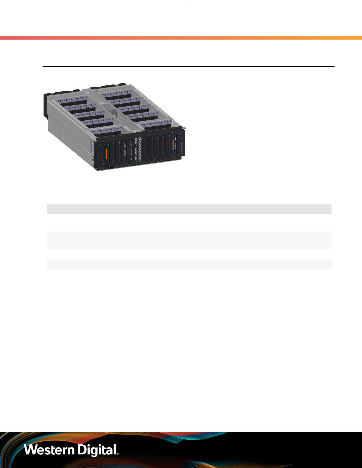
User Guide
2.1 Chassis
Figure 14: Ultrastar Data60 Chassis
2. Components
2.1 Chassis
The chassis is the primary housing that contains
and connects all of the system components of the
Ultrastar Data60 . The chassis is comprised of the
drive bay that contains all of the system data storage
drives and a number of other bays that contain the
major system components, such as the PSUs and
IOMs. Other system components are attached to
the exterior of the chassis, such as the rear fans and
rails to provide system cooling andrackmounting
capability. The chassis also houses the baseboard,
which is mounted inside the bottom of the chassis
and is the primary data pathway that connects all of
the enclosure's system components. The chassis has
internal backflow preventers to prevent hot air from
re-entering the enclosure.
2.1.1 Chassis Specifications
Specification Value
Dimensions 447 mm (W) x 807 mm (L) x 172.7 mm (H) /
Part Number 1EX0443 (dual IOMs) /
Hot Swappable? No
Weight 20 kg / 44 lbs
17.6 in. (W) x 31.77 in. (L) x 6.8 in. (H)
1EX0442 (single IOM)
35

User Guide
2.1.2 Chassis Layout
Figure 15: Chassis Component Locations
2. Components
2.1 Chassis
Table 36: Chassis Component Descriptions
Number Feature
1 IOM and IOM Fan Bay
2 Drive Bays
3 Chassis Handles
4 Rear Fans Bays
5 PSU Bays
6 IOM A Dual HD-Mini SAS Ports (x6)
7 IOM B Dual HD-Mini SAS Ports (x6)
1GB Ethernet Port (x1)
1GB Ethernet Port (x1)
36

User Guide
The Chassis has a removable lid that encloses the internal system components and ensures proper airflow.
The drive bays are comprised of 16 sections that isolate the data storage drives from transmitting vibration
to one another. A long central bay contains the enclosure's IOMs and the IOM Fan. The front of the Chassis
has a metal mesh cover and two handles that swing out from the chassis, which are used to pull the
enclosure out of the rack. Two rack ears at the front of the enclosure are used to secure the enclosure to
the rack for shipping purposes. The rear of the Chassis has two housings to shroud and connect the four
Rear Fans to the enclosure, and a center bay that houses the PSU modules.
2. Components
2.1 Chassis
Warning: The handles on the front of the chassis are not intended to be used to support the
weight of the Ultrastar Data60 . Lifting the unit by the chassis handles or trying to support
the unit on the handles can cause them to fail. This can cause serious damage to the unit or
serious bodily harm to those handling the unit. Always team lift the chassis by gripping the
underside of the unit, and never try to lift a chassis that is filled with drives.
37

User Guide
2.2 IOM
Figure 16: Ultrastar Data60 IOM
2.2.1 IOM Specifications
Each IOM provides system data connectivity
through 6 Mini-SAS HD ports, capable of four 12Gbps
SAS connections each. The IOMs are N+1 redundant,
hot-swappable components. The IOMs are installed
into the central bay from the top of the Chassis
and connects to the drive board. The baseboard
completes the connection to the Mini-SAS HD ports,
which extend out the rear of the enclosure. Each
IOM contains a primary and two SAS expander chips,
and an out-of-band management (OOBM) chip that
connects to the management port on the rear of the
enclosure.
Specification Value
Connector Type x6 HD Mini-SAS
(connected externally at the rear of the enclosure)
2. Components
2.2 IOM
Number per Enclosure 2
Part Number 1EX2201
Hot Swappable? Yes
FRU or CRU? CRU
Weight 1.27 kg / 2.8 lbs
38

User Guide
2.2.2 IOM Layout
Figure 17: IOM Component Locations
2. Components
2.2 IOM
Table 37: IOM Component Descriptions
Number Feature
1 IOM Handles
2 Latch Release
3 Internal IO Connector
4 Card Edge Power Receptacle
5 Internal IO Connector
2.2.3 IOM Blank
Figure 18: Ultrastar Data60 IOM Blank
The IOM Blank is a placeholder component for filling
the unused IOM slot in versions of the Ultrastar
Data60 that do not leverage redundant IOMs.
The IOM Blank may only be installed into IOM slot
B under all circumstances. From the front of the
enclosure, slot B is the left-hand slot. It is necessary
to have a blank installed in this unused slot in order
to ensure the airflow remains within the operational
parameters designed for the enclosure; the IOM
Blank has no function beyond this.
39
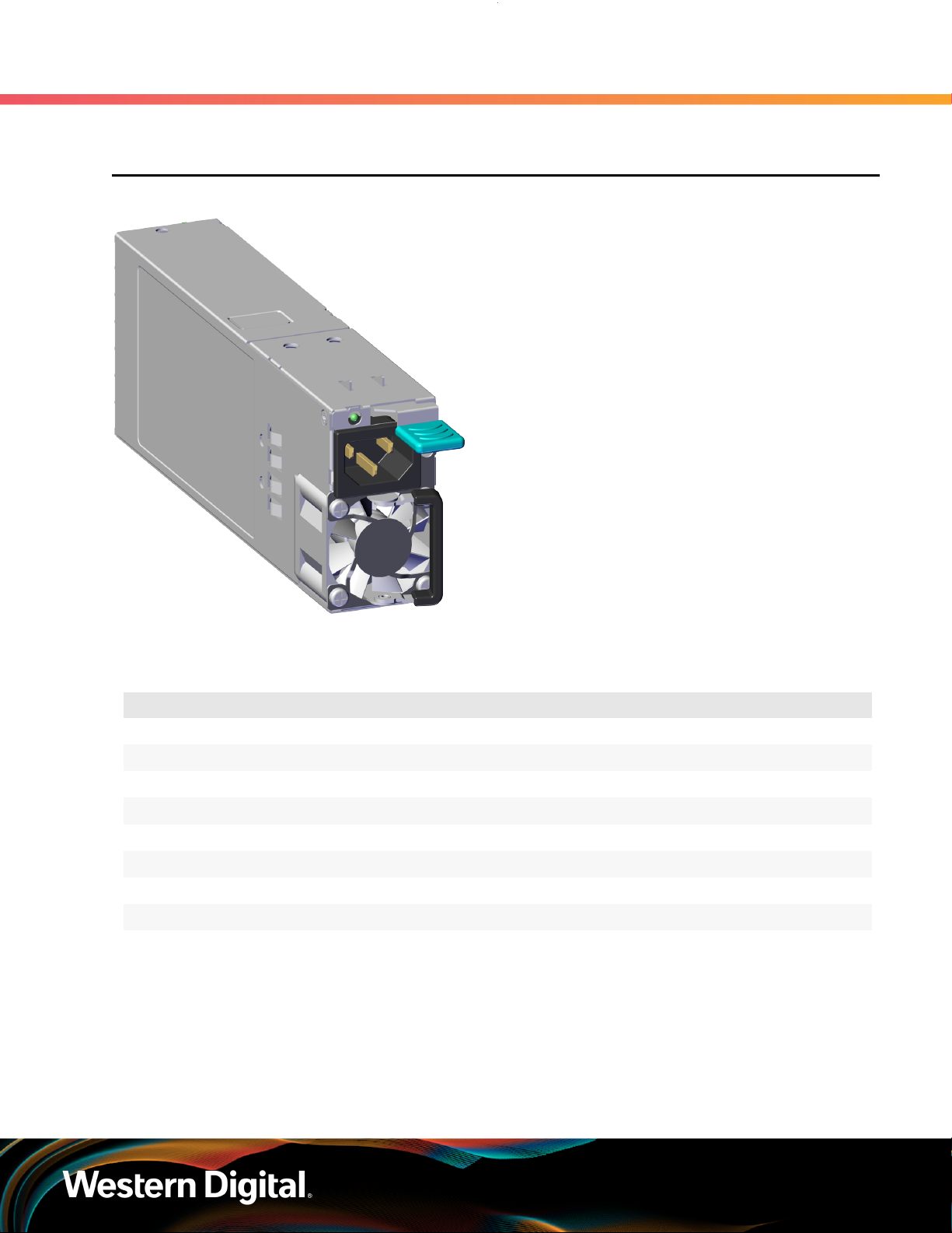
User Guide
2.3 PSU
Figure 19: Ultrastar Data60 PSU
2. Components
2.3 PSU
The Ultrastar Data60 contains redundant 1600W
Power Supply Units (PSUs). Each PSU requires an
input voltage between 200 - 240 VAC. The PSUs
are 80 PLUS Platinum certified and utilize C14 power
cable receptacles.
2.3.1 PSU Specifications
Specification Value
Power Output 1600W
80 PLUS Standard Platinum
Input Voltage 200 - 240 VAC
Connector Type C14
Number per Enclosure 2
Part Number 1EX0434
Hot Swappable? Yes
FRU or CRU? CRU
Weight 1 kg / 2.2 lbs.
40

User Guide
2.3.2 PSU Layout
Figure 20: PSU Component Locations
2. Components
2.3 PSU
Table 38: PSU Component Descriptions
Number Feature
1 Internal Connector
2 C14 Power Receptacle
3 Latch Release Lever
4 Fan
5 Handle
41

User Guide
2.4 Rear Fan
Figure 21: Ultrastar Data60 Rear Fan
2. Components
2.4 Rear Fan
The Rear Fans are toolless modules that provide the
primary system cooling for the Ultrastar Data60 .
They are attached inside the fan housing at the rear
of the chassis by two latches and a 6-pin connector,
which also provides power and control signals to
the modules.
2.4.1 Rear Fan Specifications
Specification Value
Number per Enclosure 4
Part Number 1EX0433
Hot Swappable? Yes
FRU or CRU? CRU
Weight 318 g / .7 lbs
42

User Guide
2.4.2 Rear Fan Layout
Figure 22: Rear Fan Component Locations
2. Components
2.4 Rear Fan
Table 39: Rear Fan Component Descriptions
Number Feature
1 Fan
2 Latch Releases
3 Internal Power and IO Connector
43
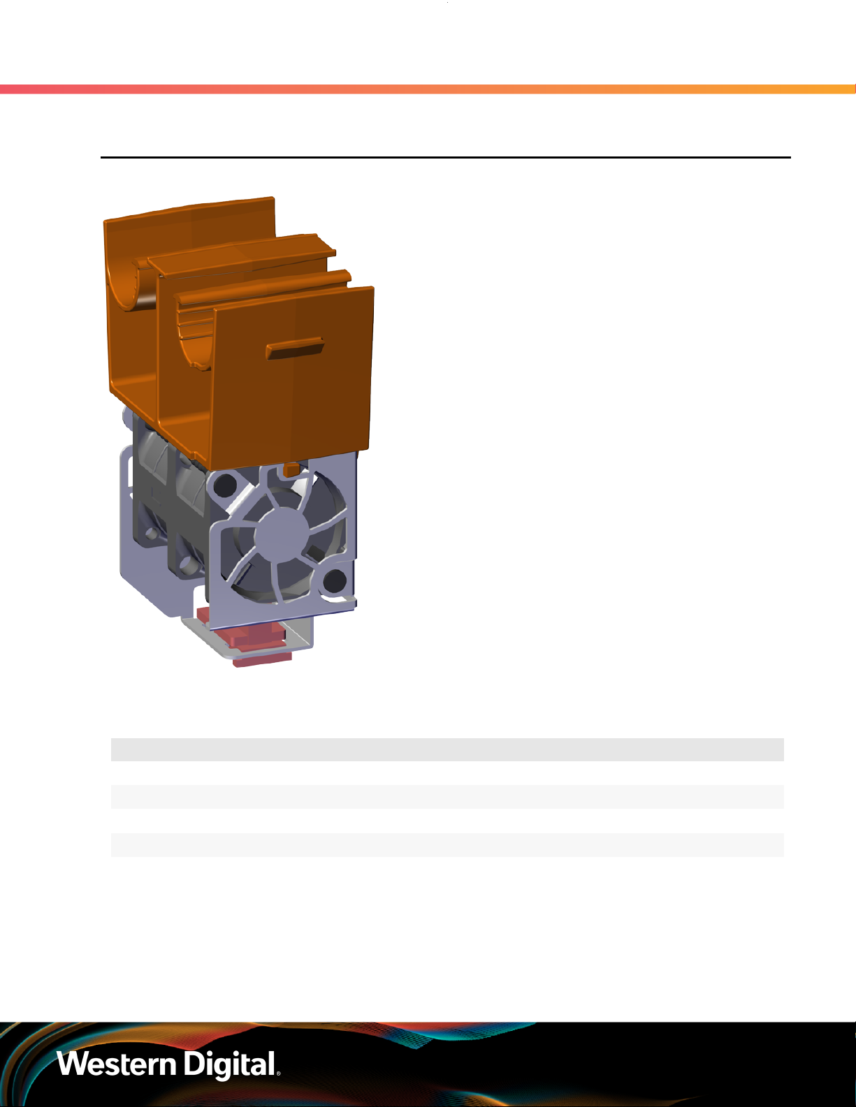
User Guide
2.5 IOM Fan
Figure 23: Ultrastar Data60 IOM Fan
2. Components
2.5 IOM Fan
The IOM Fan is designed to focus cooling on the
enclosure's IOMs. It is installed into the central
bay of the chassis and is accessed from the top
of the enclosure through the removable cover. It
is attached to the chassis via a toolless release
mechanism that allows for easy replacement.
2.5.1 IOM Fan Specifications
Specification Value
Number per Enclosure 1
Part Number 1EX0432
Hot Swappable? Yes
FRU or CRU? CRU
Weight 181.4 g / .4 lbs
44

User Guide
2.5.2 IOM Fan Layout
Figure 24: IOM Fan Component Locations
2. Components
2.5 IOM Fan
Table 40: IOM Fan Component Descriptions
Number Feature
1 Latch Mechanism
2 Fan Module
3 Internal Connector
45

User Guide
2.6 Rails
Figure 25: Ultrastar Data60 Rails
2.6.1 Rails Specifications
2. Components
2.6 Rails
The Ultrastar Data60 is installed into a rack using a
toolless-attach rail system. Each rail is a two-piece
assembly, with one rail that attaches directly to
the chassis (inner rail) and another (outer rail) that
attaches to the rack. The inner rail comes nested
inside the outer rail and can be accessed by sliding
it out of the outer rail. The outer rails attach to the
rack and receive the chassis to support it inside
the rack. The outer rails attach to vertical rack rails,
which should be set between 24 in.-32 in.. The
toolless design allows an installer to attach the
rails to a rack without any tools, which simplifies
installation. Once they are attached, they can be
secured with the included M5 screws and washers.
Specification Value
Length 1028.7 mm / 40.5 in.
Part Number 1EX0436
Hot Swappable? No
FRU or CRU? CRU
Weight 6.07 kg total (3.03 kg per rail) / 13.4 lbs. total (6.7 per rail)
46

User Guide
2.6.2 Rails Layout
Figure 26: Rails Component Locations
2. Components
2.6 Rails
Table 41: Rails Component Descriptions
Number Features
1 Upper CMA Connector
2 Lower CMA Connector
3 Rear Rack Mounting Bracket
4 Rear Latch Release
5 Rear Cover Alignment Bracket
6 Inner Rail
7 Front Rack Mounting Bracket and Latch Release
47
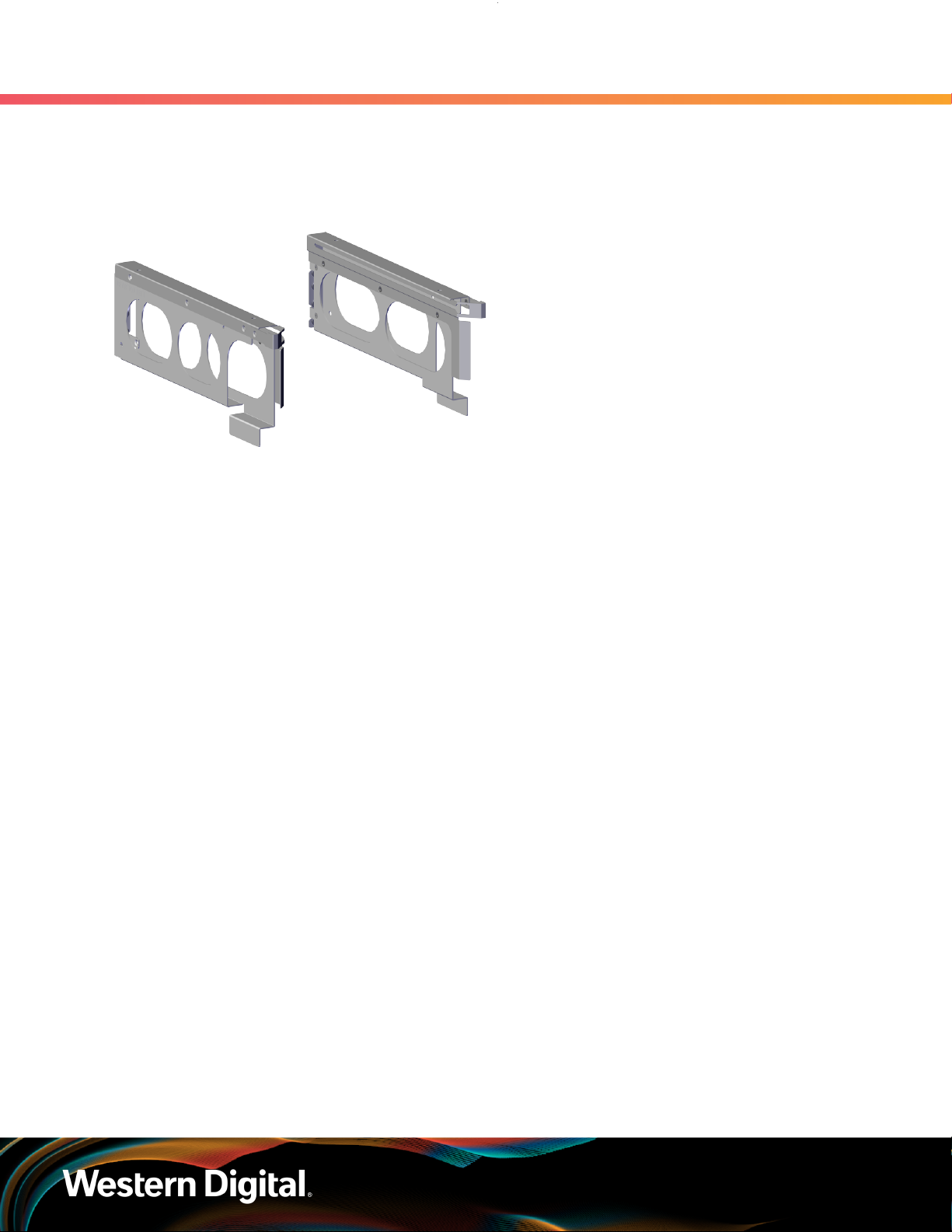
User Guide
2.6.3 Rear Cover Alignment Bracket
Figure 27: Ultrastar Data60 Rear Cover
Alignment Brackets
2. Components
2.6 Rails
The Rear Cover Alignment Brackets are designed to
keep the top cover of the Chassis in the rack while
extending the Ultrastar Data60 out of the rack for
servicing. The Rear Cover Alignment Brackets attach
to the rear vertical rack rails and rest on top of the
toolless rail system.
48

User Guide
2.7 CMA
Figure 28: Ultrastar Data60 CMA
The Ultrastar Data60 CMA is a two-arm design that separates the connections to the two sides of the
enclosure. The lower arm supports the cables that connect to the dual SAS ports and Ethernet on the right
hand side of the unit as viewed from the rear, as well as the lower PSU power cord. The upper arm supports
the left hand ports and the upper PSU power cord. Each arm is attached to the Ultrastar Data60 by one clip
at the elbow and two at the other end. The cables are secured to the arms by plastic clips called baskets
that can be opened at the top to adjust, add, or remove cables. The arms can also be moved into a service
position by unclipping them from the elbow end of the arm and swinging them away from the enclosure
when the enclosure is fully inserted in a rack. This provides access to connections and components at the
rear of the system without having to remove the CMA or disconnect any of the cabling.
2. Components
2.7 CMA
The cable management assembly (CMA) protects
and manages the cables connected to the PSU
ports, SAS ports, and Ethernet ports. It prevents
damage to the port connectors and the cables
throughout the full travel of the enclosure as it is
pulled out of the rack for servicing. This motion
ensures that the cables contained by the CMA arm
do not snag or get pulled out of the ports as the
enclosure moves.
2.7.1 CMA Specifications
Specification Value
Extension Range 0 - 36 in.
Number per Enclosure 1 assembly (2 arms)
Part Number
Hot Swappable? No
Maximum Number of Cables
FRU or CRU? CRU
Weight 1.54 kg (0.77 per arm) / 3.4 lbs. (1.7 per arm)
12 SAS Cables
2 Power Cords
2 Ethernet Cables
49

User Guide
2.7.2 CMA Layout
Figure 29: CMA Component Locations
2. Components
2.7 CMA
Table 42: CMA Component Descriptions
Number Feature
1 Crossbar
2 Rail and Rack Connectors
3 Baskets (retain cables)
4 Arm
5 Elbow Connector
50

User Guide
2.7.3 CMA Cable Tray
Figure 30: Overview Image
The cable management assembly (CMA) comes with an optional tray that is used to support cable loads
greater than ten (five per arm). The CMA Cable Tray is mounted at the bottom-rear of the chassis using four
M3 x 8mm T10 Torx screws (two per side). It is useful in situations where cables might interfere with the
lower U space beneath the chassis.
2. Components
2.7 CMA
51

User Guide
2.8 3.5in HDD Assembly
Figure 31: Ultrastar Data60 3.5in HDD
Assembly
2. Components
2.8 3.5in HDD Assembly
The 3.5in HDD Assembly is comprised of two parts:
the storage drive and the drive carrier. The carrier
attaches to the exterior of the data storage drive and
caddies the drive into the enclosure. It stabilizes the
motion of the drive into the drive bay so that the
drive properly mounts onto the drive board.
2.8.1 3.5in HDD Assembly Specifications
Specification Value
Number per Enclosure up to 60 drives
Part Number See the List of Compatible Drives (page 22)
to find the specific part number required.
Hot Swappable? Yes
Weight .68 kg / 1.5 lbs.
52
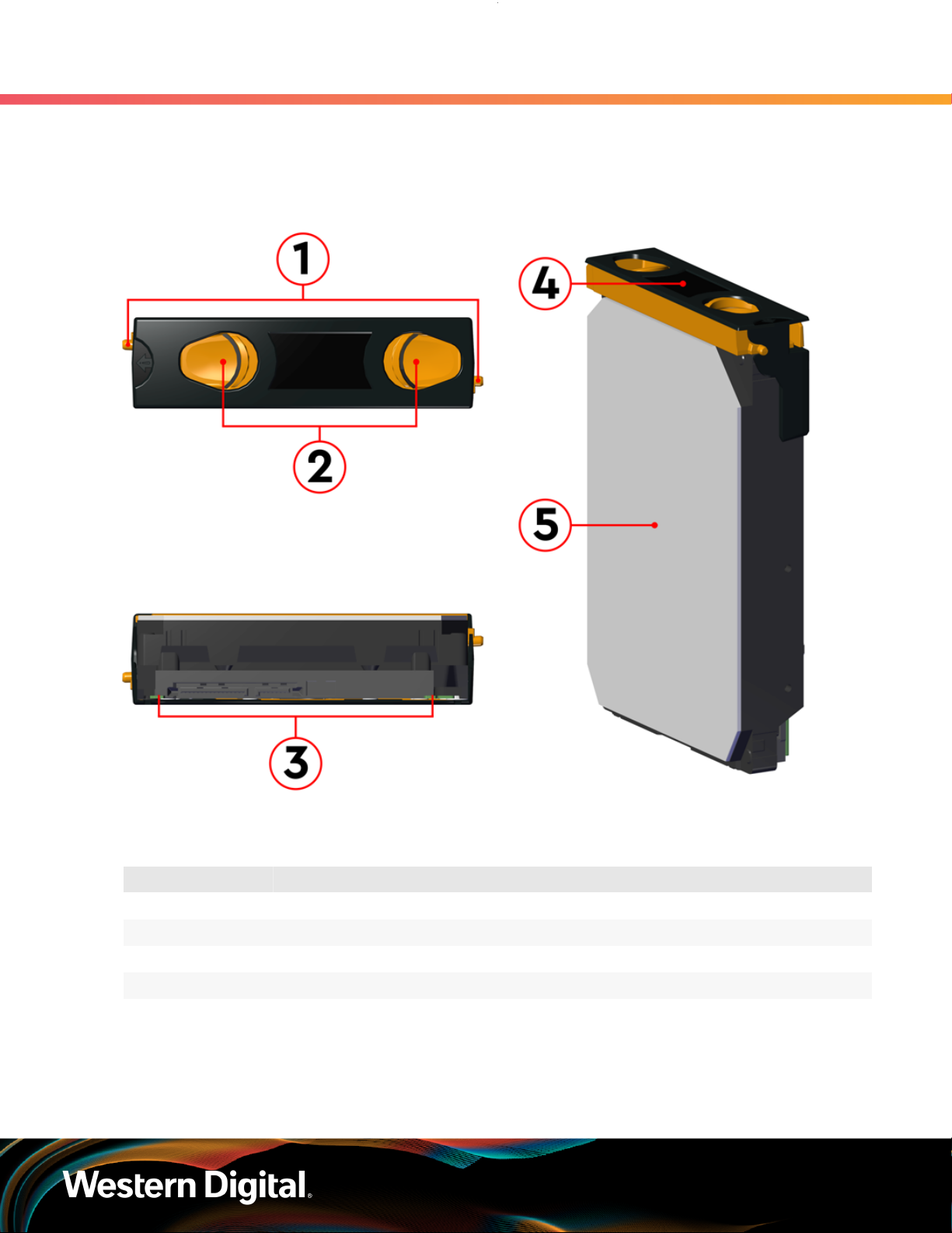
User Guide
2.8.2 3.5in HDD Assembly Layout
Figure 32: 3.5in HDD Assembly Component Locations
2. Components
2.8 3.5in HDD Assembly
Table 43: 3.5in HDD Assembly Component Descriptions
Number Feature
1 Latches
2 Latch Release
3 IO and Power Connectors
4 Drive Carrier
5 Disk Drive
53
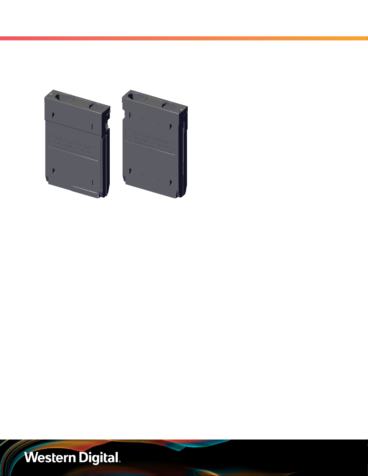
User Guide
2.8.3 3.5in Drive Blank
Figure 33: Ultrastar Data60 3.5in Drive
Blank
2. Components
2.8 3.5in HDD Assembly
The 3.5in Drive Blank is a placeholder component
used to fill empty drive slots in the chassis when an
Ultrastar Data60 enclosure is partially populated
with drives. When the number of drives in a row
is less then the total necessary to fill that row, the
3.5in Drive Blank is used to fill out the row in place
of actual drives. The purpose of the 3.5in Drive
Blank is to maintain proper airflow and cooling
of the enclosure and the components within the
enclosure. For more information on requirements
for a partially populated enclosure, see Partial
Population Configurations (page 214).
54

User Guide
1
2
3
4
2.9 2.5in SSD Assembly
Figure 34: 2.5in SSD Assembly Component
Locations
2. Components
2.9 2.5in SSD Assembly
The 2.5in SSD Assembly is used to adapt a 2.5" form
factor SSD to the 3.5" drive slots in the Ultrastar
Data60 drive bays. This allows the enclosure to
accommodate high speed SSD drives as its primary
data storage medium. The carrier operates by
utilizing an innovative clamping mechanism. The 2.5"
drive is seated in the orientation shown the overview
image. Then the clamp is inserted to apply pressure
to the SSD and secure it in place.
Table 44: 2.5in SSD Assembly Component Descriptions
Number Feature
1 Drive Holder Clamp
2 SSD
3 Carrier Shell
4 Drive Latch Release
2.9.1 Operating the 2.5" Drive Carrier
Follow these steps to operate the clamping mechanism and install a 2.5" drive in the carrier.
Step 1 : Locate the release clips on the rear and press them inward to release the clamp.
55

User Guide
Step 2 : Slide the clamp in the direction shown in the following image to loosen it from the drive. Be
2. Components
2.9 2.5in SSD Assembly
Figure 35: Clamp Release (clamp shown in blue for visual clarity)
sure not to slide too far as this will allow the clamp to fall from the carrier body and it will have
to be reinstalled.
Figure 36: Clamp Slide (clamp shown in blue for visual clarity)
Step 3 :
Step 4 : Slide the clamp back toward the drive making sure that the two plastic pins on the side of the
Insert the 2.5" drive into the drive slot so that it is snug into the corner.
drive properly install into the drive screwholes. If these pins are not seated properly, unlatch the
clamp and retry.
56

User Guide
2. Components
2.9 2.5in SSD Assembly
Figure 37: Clamp Pins (clamp shown in blue for visual clarity)
57

Western Digital
Support
In This Chapter:
- Part Replacement Service Window............59
- IOM Replacement.........................................59
- PSU Replacement.........................................62
- Rear Fan Replacement.................................66
- IOM Fan Replacement..................................69
- 3.5in HDD Assembly Replacement.............. 71
- CMA Replacement........................................75
- Rails Replacement........................................90
- Chassis Replacement.................................. 119
- Special Considerations for Cable
Routing.......................................................... 154
- Cabling for CMA..........................................156
58

User Guide
3.1 Part Replacement Service Window
The following table contains a time required and a replacement window related to each hot swappable
replacement part within the enclosure. The time required for replacement is the expected amount of time it
requires to replace the part. The replacement window is the amount of time that the enclosure can be open
for servicing. If the enclosure cover is open for a period lasting longer than the replacement window, the
enclosure may reduce access to drives and other components to reduce the occurrence of thermal issues.
Table 45: Replacement Service Window
Part Time Required Replacement Window
IOM 5 min 1 min
PSU 5 min 1 min
Rear Fan 5 min 1 min
IOM Fan 5 min 1 min
3.5in HDD Assembly 5 min 1 min
3. Support
3.1 Part Replacement Service Window
Attention: In the case of multiple part failures, a failed fan should always be replaced before
any other part. Once the enclosure cover is open, the failed fan must be removed within
a minute. The remainder of the fan replacement should be completed within the 5 minute
window.
3.2 IOM Replacement
Before you begin:
Important: Standard zoning methods (i.e. WDDCS Tool, OOBM, sg_senddiag, or SMP zoning
commands) require each IOM to be configured individually. After replacing an IOM, zoning
should be configured on it before the system is put back into production, otherwise, any host
that is booted and has access to that IOM will see all drives. File-based zoning does not require
individual IOM zoning configuration after replacement, as the zoning configuration is stored on
the baseboard.
Personnel Required 1
Avg. Replacement Time 1 min
Max Replacement Time 5 min
Tool # Needed
None N/A N/A
Replacement Requirements
Required vs.
Recommended
59

User Guide
Step 1 : Grasp both handles at the front of the enclosure and pull with even pressure to extend the
3. Support
3.2 IOM Replacement
chassis out of the rack until it is stopped by the safety latches. The safety latches will prevent the
enclosure from coming out of the rack completely and the cover will remain in the rack attached
to the rear alignment brackets.
Figure 38: Chassis Handle Operation
Step 2 :
Step 3 : Uninstall the IOM(s).
Locate the faulty IOM by the amber LED that will be lit on top if there is a fault or by activating
the identify LED on the IOM being replaced.
a. Locate the latch release on the IOM and press it in the direction shown in the following
image.
Figure 39: Unlatching the IOM
Grasp both handles, one handle in each hand, and lift evenly with both hands to ensure the
b.
IOM comes out straight. This will prevent any damage to the pins on the internal connectors.
60

User Guide
3. Support
3.2 IOM Replacement
Figure 40: Removing IOM
Step 4 :
Step 5 : Install the IOM.
Remove the new IOM from its packaging.
Caution: If a pin on the IOM’s internal connectors is bent or damaged, the IOM will
have to be replaced. For this reason it is imperative that the IOM is not forced into
position, that it is inserted straight, and that the directions for installing the IOM are
followed exactly.
Ensure that the handles on the IOM are not latched. To unlatch them, press the latch release
a.
in the direction shown in the following image.
Figure 41: Unlatching IOM Handles
b. Align the IOM with the empty slot on the top of the chassis so that the arrow on the IOM
latch release is facing toward the side shown in the following image.
c.
Slowly lower the IOM into the empty slot while being careful to keep it level. Do not to force
it.
61

User Guide
3. Support
3.3 PSU Replacement
Figure 42: Installing the IOM
d. When the IOM is lowered fully, apply light pressure with both hands evenly on the IOM body,
not the handles, to seat the IOM in the connector. If the IOM won’t seat correctly, DO NOT
FORCE IT. Instead, back the IOM out, check the pins to make sure none are damaged, and
try again.
e. Once the IOM is seated properly in the slot, close the handles until they latch closed.
Step 6 :
Step 7 : Check the fault LEDs on the IOM or on the enclosure's front and rear LED panels to determine if
Step 8 :
Push the chassis back into the rack. Verify that the fans have slowed to their regular RPM. This
ensures that the enclosure is back to its proper cooling settings.
there is a firmware mismatch between the replacement IOM and the IOM that was not replaced.
If the fault LED is illuminated, open a command prompt on the host server and issue the
a.
following command using SG3_utils.
sg_ses <dev> -p 3
Remember to replace the <dev> field with the appropriate value related to the IOM in slot
A.
b. Scan the output for the ESCE element status descriptor. If it is critical, then there is a
firmware mismatch.
c. To fix the firmware mismatch, perform an upgrade to the current firmware revision by
following the upgrade instructions here: Firmware Upgrade (page 161)
If zoning was configured via the WDDCS Tool, OOBM, sg_senddiag, or SMP zoning commands,
these methods require each IOM to be configured individually. Configure zoning on the new IOM
before the system is put back into production. For instructions on zoning, please see Zoning
(page 180).
3.3 PSU Replacement
Replacement Requirements
Personnel Required 1
Avg. Replacement Time 1 min
Max Replacement Time 5 min
62

User Guide
3. Support
3.3 PSU Replacement
Tool # Needed
None N/A N/A
Step 1 : Place the CMA(s) into service position.
a. Unlatch the CMA(s) from the rail at the elbow connector by pressing the blue release button.
Figure 43: Unlatching a CMA Connector
b. Swing the CMA(s) away from the enclosure.
The arm(s) should be extended away from the enclosure as shown in the following example.
c.
Required vs.
Recommended
Figure 44: CMA(s) in service position (Cables not shown)
Step 2 :
Step 3 : Detach the retention clip from the PSU cable.
Locate the faulty PSU by finding the amber LED lit at the rear of the enclosure.
63
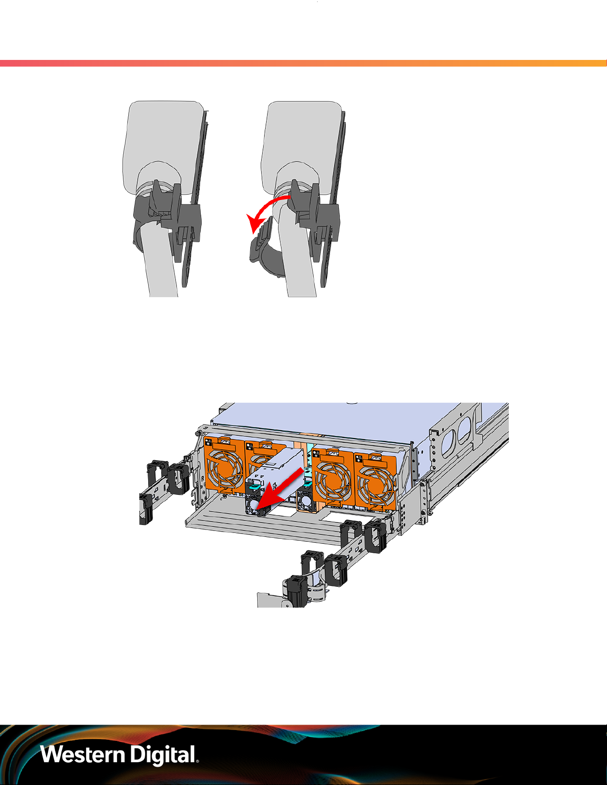
User Guide
3. Support
3.3 PSU Replacement
Figure 45: Cable Retention Mechanism
Step 4 : Remove the power cable from the faulty PSU.
Step 5 : Uninstall the PSU.
a. Grasp the release lever and the metal handle in a downward pinching motion to release the
latching mechanism.
Figure 46: Uninstalling PSU
b. Pull the PSU straight out with even pressure.
Step 6 :
Step 7 : Install the PSU.
Remove the new PSU from its packaging.
a. Align the PSU in the orientation shown in the following image.
Slide the PSU into the slot until it seats fully into the chassis.
b.
64
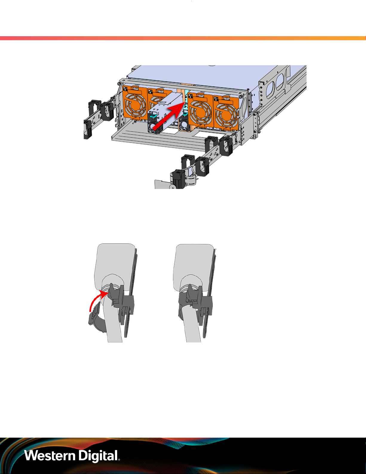
User Guide
3. Support
3.3 PSU Replacement
Figure 47: Installing the PSU
c. Plug the power cable into the receptacle at the back of the PSU.
d. Loop the retention clip around the PSU cable and pinch it until the clip catches and locks in
place.
Figure 48: Cable Retention Mechanism
e.
Slide the retention clip forward until it stops near the cable connector. Doing this will ensure
that the retention clip functions properly in the event the cable is pulled on for some reason.
65

User Guide
3. Support
3.4 Rear Fan Replacement
Figure 49: Cinching Cable Retention Clip
Step 8 :
Make sure the CMA(s) is in operational position by folding the arm(s) in toward the enclosure and
attaching the elbow end(s) to the connector(s) attached to the rail. Verify that all of the cabling is
in functional order and does not bind or catch.
3.4 Rear Fan Replacement
Personnel Required 1
Avg. Replacement Time 1 min
Max Replacement Time 5 min
Tool # Needed
None N/A N/A
Step 1 : Place the CMA(s) into service position.
a. Unlatch the CMA(s) from the rail at the elbow connector by pressing the blue release button.
Replacement Requirements
Required vs.
Recommended
66

User Guide
3. Support
3.4 Rear Fan Replacement
Figure 50: Unlatching a CMA Connector
b. Swing the CMA(s) away from the enclosure.
The arm(s) should be extended away from the enclosure as shown in the following example.
c.
Figure 51: CMA(s) in service position (Cables not shown)
Step 2 : To unlatch the rear fan from the fan housing, use one hand to press the clip at the top and
bottom of the fan and pull to free it from the chassis and remove it.
67
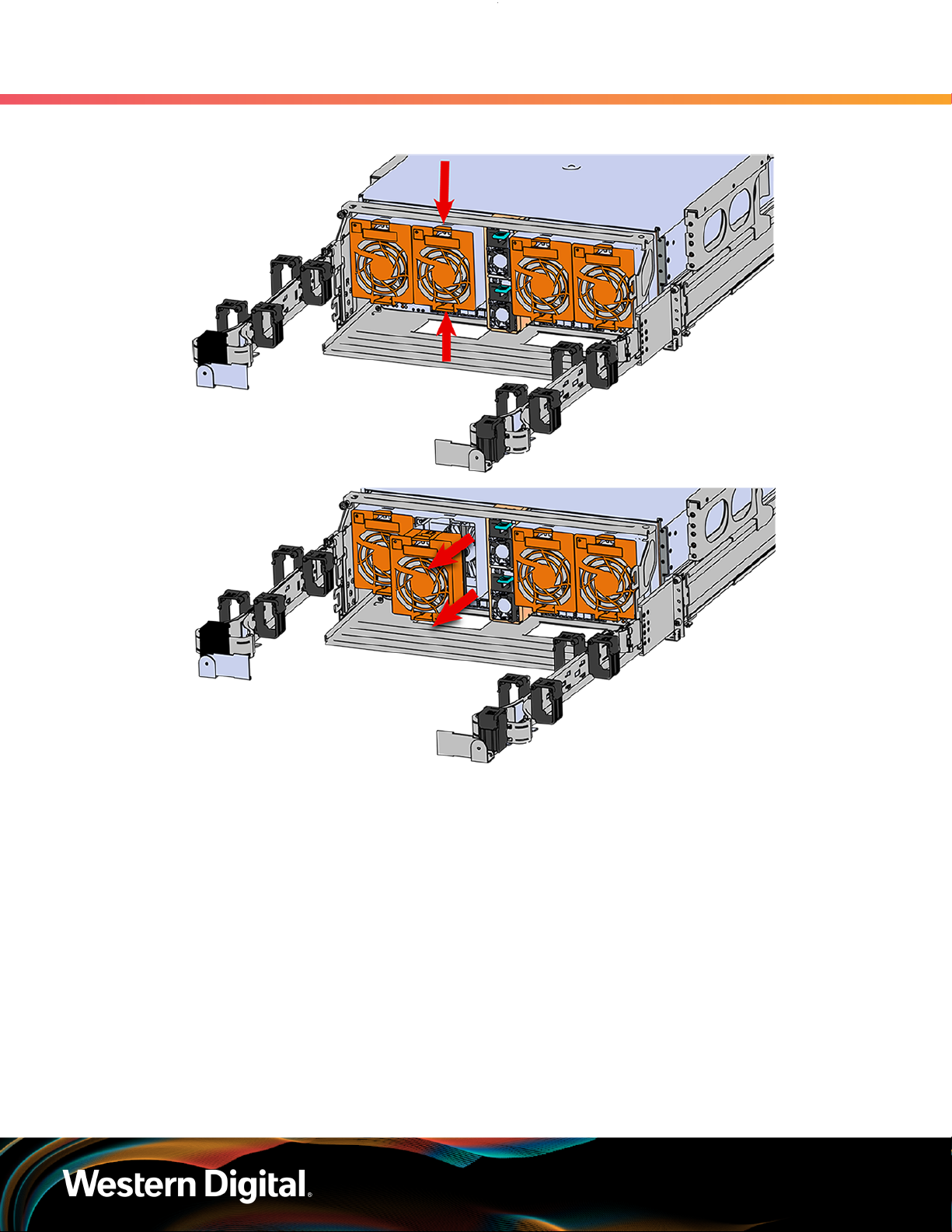
User Guide
3. Support
3.4 Rear Fan Replacement
Figure 52: Uninstalling the Rear Fan
Step 3 : Install Rear Fan
a. Orient the rear fan as shown in the following image.
Insert the rear fan into the housing as shown in the following image.
b.
68

User Guide
3. Support
3.5 IOM Fan Replacement
Figure 53: Installing the Rear Fan
Step 4 :
Make sure the CMA(s) is in operational position by folding the arm(s) in toward the enclosure and
attaching the elbow end(s) to the connector(s) attached to the rail. Verify that all of the cabling is
in functional order and does not bind or catch.
3.5 IOM Fan Replacement
Personnal Required 1
Avg. Replacement Time 1 min
Max Replacement Time 5 min
Tool # Needed
None N/A N/A
Step 1 : Grasp both handles at the front of the enclosure and pull with even pressure to extend the
chassis out of the rack until it is stopped by the safety latches. The safety latches will prevent the
enclosure from coming out of the rack completely and the cover will remain in the rack attached
to the rear alignment brackets.
Replacement Requirements
Required vs.
Recommended
69

User Guide
Step 2 : Remove the IOM Fan.
3. Support
3.5 IOM Fan Replacement
Figure 54: Chassis Handle Operation
a. With one hand, grasp around the center square of the fan housing as shown in the following
image.
Pinch the IOM fan housing to release the latching mechanism and pull it straight out from the
b.
chassis.
Figure 55: Removing IOM Fan
Step 3 : Install the IOM Fan.
a. Align the IOM Fan as shown in the following image.
70
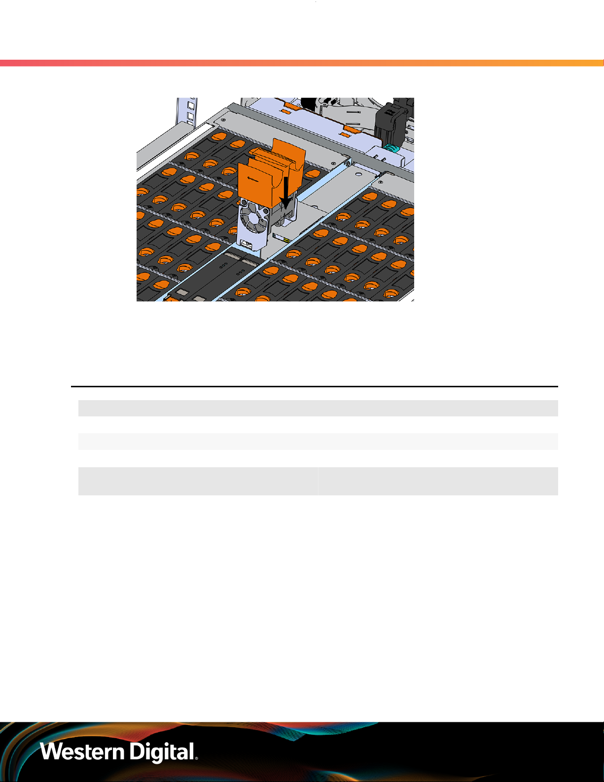
User Guide
3. Support
3.6 3.5in HDD Assembly Replacement
Figure 56: Installing the IOM Fan
b. Pinch the latch release mechanism slightly and carefully lower the IOM Fan into the slot.
Step 4 : Push the enclosure back into the rack to ensure proper cooling.
3.6 3.5in HDD Assembly Replacement
Replacement Requirements
Personnal Required 1
Avg. Replacement Time 1 min
Max Replacement Time 5 min
Tool # Needed
None N/A N/A
Step 1 : Grasp both handles at the front of the enclosure and pull with even pressure to extend the
chassis out of the rack until it is stopped by the safety latches. The safety latches will prevent the
enclosure from coming out of the rack completely and the cover will remain in the rack attached
to the rear alignment brackets.
Required vs.
Recommended
71

User Guide
Only extend the enclosure out of the rack as far as is needed to reach the drive being replaced.
Step 2 : Locate the faulty 3.5in HDD Assembly by finding the illuminated amber LED or by activating the
3. Support
3.6 3.5in HDD Assembly Replacement
Figure 57: Chassis Handle Operation
identification LED for the drive to be replaced.
Figure 58: HDD Assembly LED
Step 3 : Follow these steps to remove a 3.5in HDD Assembly.
a. Find the latch release mechanism on the 3.5in HDD Assembly being removed.
Insert a finger and a thumb into the latch release and pinch to unlatch the 3.5in HDD
b.
Assembly.
72

User Guide
3. Support
3.6 3.5in HDD Assembly Replacement
Figure 59: Unlatch Drive Carrier (IOM Not Shown)
c. Lift the 3.5in HDD Assembly free from the enclosure.
Figure 60: Removing 3.5in HDD Assembly
Step 4 :
Step 5 : Install the 3.5in HDD Assembly.
Remove the new 3.5in HDD Assembly from its packaging.
73

User Guide
3. Support
3.6 3.5in HDD Assembly Replacement
Note: The 2.5in SSD Assembly is installed in the same manner as the 3.5in HDD
Assembly. For instructions on assembling the 2.5in SSD Assembly, see Operating
the 2.5" Drive Carrier (page ).
a. Ensure that the enclosure has been pulled out of the rack until the rail latches engage.
Find the LED pointer on the top of the drive carrier. This pointer should point toward the
b.
front of the unit as shown in the following image.
Figure 61: LED Pointer Orientation
c. Align the drive with the empty slot that will receive it. Lower it into the slot, making sure it
stays level and does not snag.
74
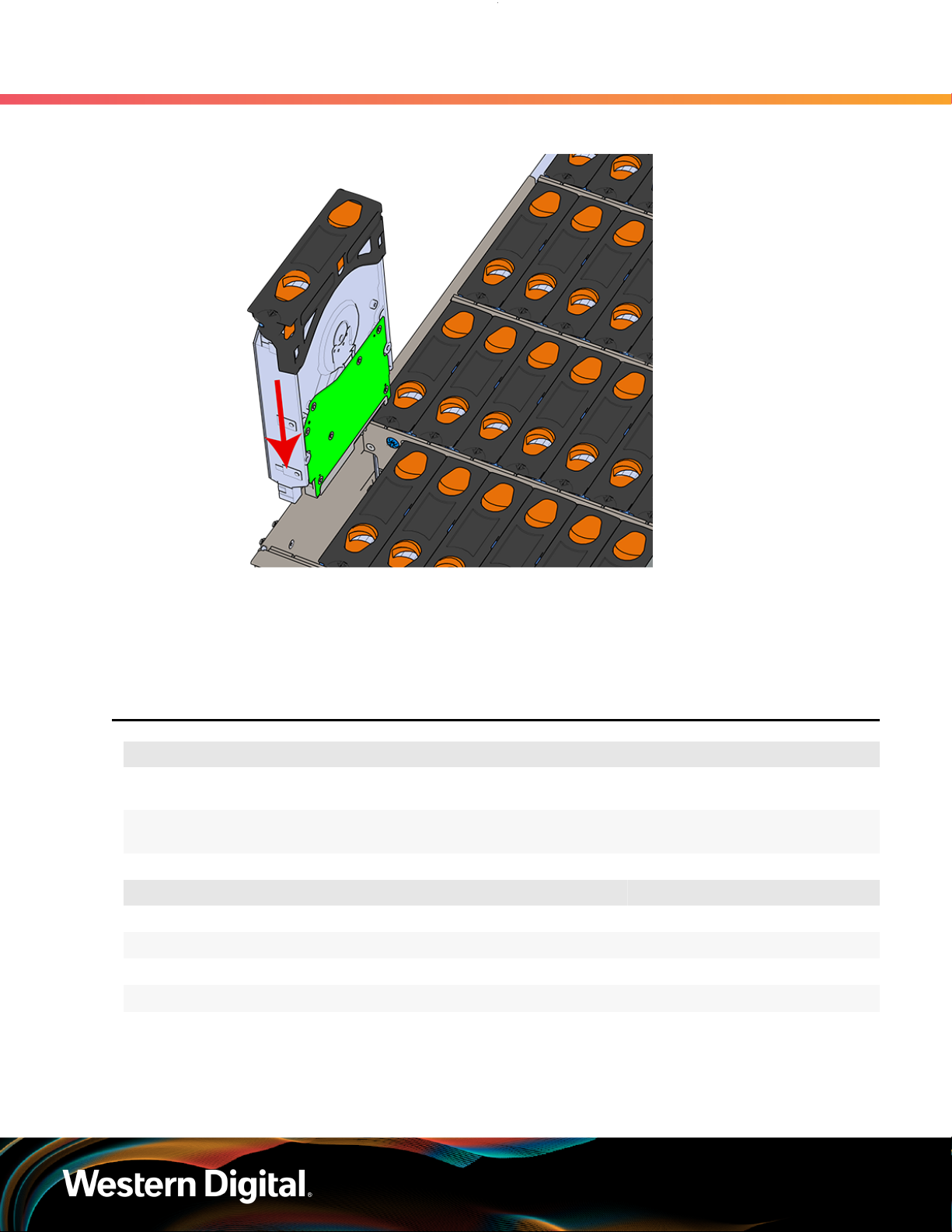
User Guide
3. Support
3.7 CMA Replacement
Figure 62: Installing a 3.5in HDD Assembly
d. Pinch the latch release and carefully press downward to seat the 3.5in HDD Assembly the
rest of the way.
Step 6 :
Push the enclosure back into the rack to ensure proper cooling.
3.7 CMA Replacement
Personnal Required
Avg. Replacement Time
Max Replacement Time
# 2 Philips Screwdriver Required
Cable Ties (for configurations with greater than 10 total cables) Recommended
Tape Measure Recommended
Low-Profile M4 x 3.2mm Philips screws Recommended
Step 1 : Place the CMA(s) into the service position.
a. Unlatch the CMA(s) at the elbow connector by pressing the blue release button to unlatch
the connector from the rail.
Replacement Requirements
1
15m
Tool Required vs. Recommended
75
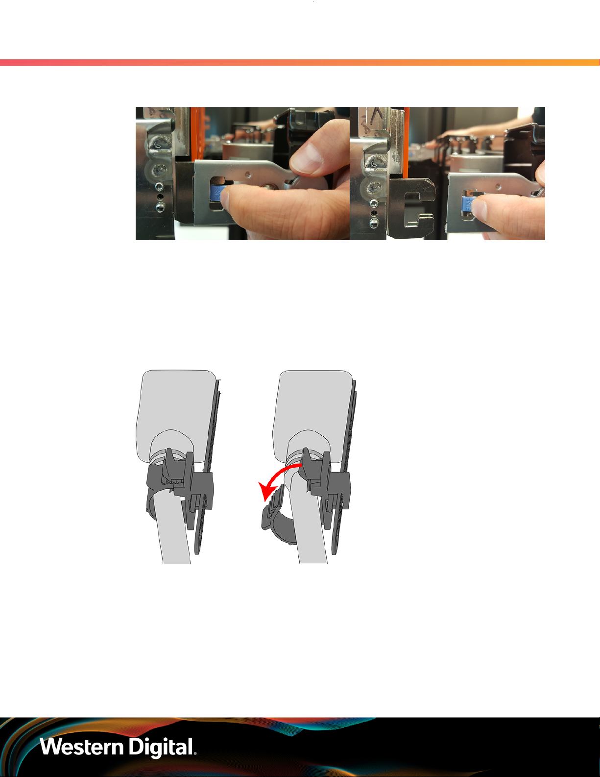
User Guide
Step 2 : Disconnect the Enclosure from power.
Figure 63: Unlatching a CMA Connector
b. Swing the CMA(s) away from the enclosure.
c. The CMA arm(s) should be extended away from the enclosure.
a. Locate the redundant PSUs at the rear of the enclosure.
Detach the cable retention clip from both power cords.
b.
3. Support
3.7 CMA Replacement
Figure 64: Cable Retention Mechanism
c. Power down the enclosure by disconnecting both power cables, one from each PSU.
Step 3 :
Step 4 : Uncable the CMA(s).
Disconnect the remaining cables from the enclosure.
a. Open all of the baskets on the CMA.
76
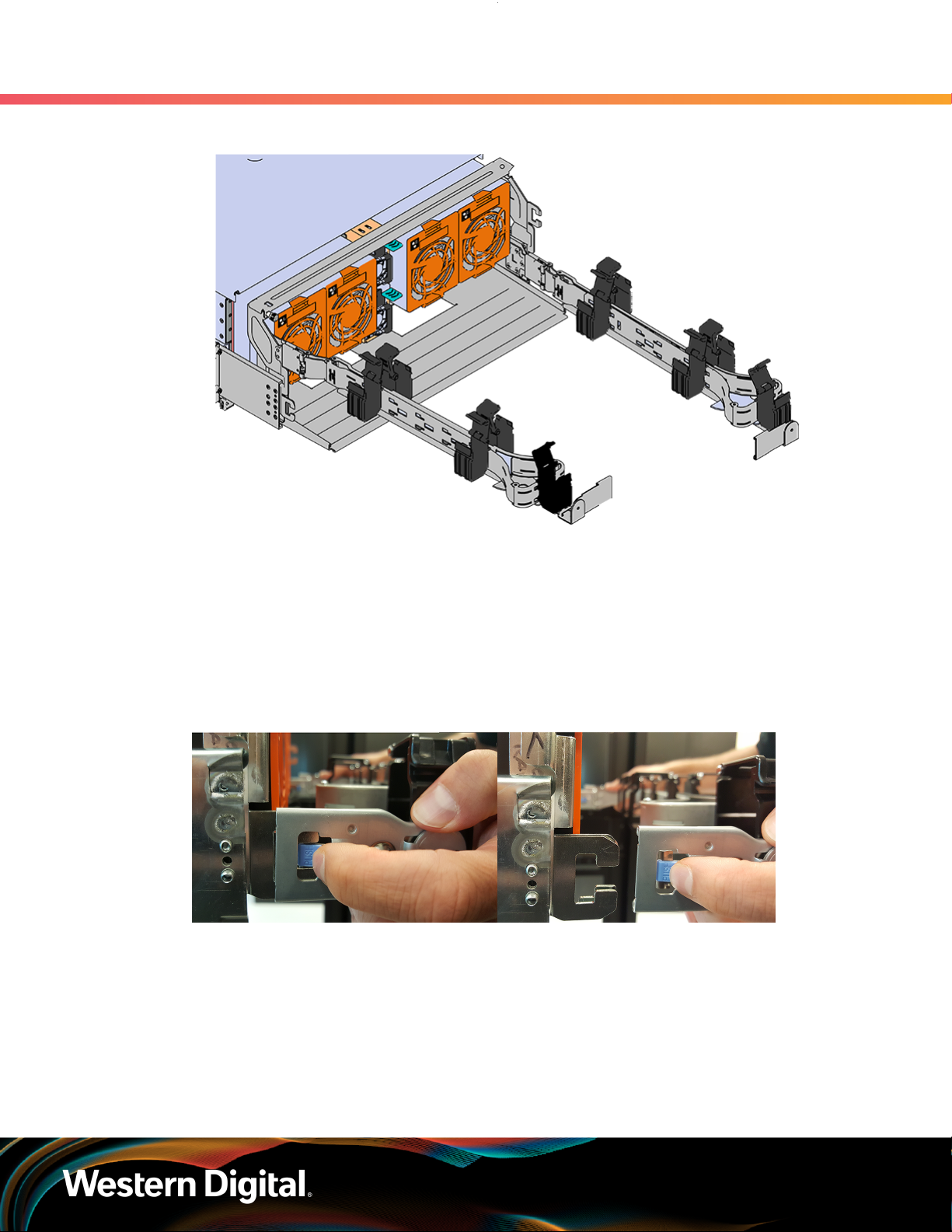
User Guide
3. Support
3.7 CMA Replacement
Figure 65: Open Baskets
b. Remove one cable from the CMA at a time making sure not to put too much strain on the
arm.
c. Repeat these steps to remove the cables from the second arm.
Step 5 : Unlatch all of the connectors that attach the CMA(s) to the enclosure and the rail by locating
the latch release button and pressing it from either side of the latch. There are three total
connections that need to be removed, one at the elbow and two at the opposite end.
Figure 66: Unlatching a CMA Connector
Step 6 : Grasp both handles at the front of the enclosure and pull with even pressure to extend the
chassis out of the rack until it is stopped by the safety latches. The safety latches will prevent the
enclosure from coming out of the rack completely and the cover will remain in the rack attached
to the rear alignment brackets.
77

User Guide
Step 7 : Follow these steps to remove a 3.5in HDD Assembly.
3.7 CMA Replacement
Figure 67: Chassis Handle Operation
a. Find the latch release mechanism on the 3.5in HDD Assembly being removed.
Insert a finger and a thumb into the latch release and pinch to unlatch the 3.5in HDD
b.
Assembly.
Figure 68: Unlatch Drive Carrier (IOM Not Shown)
3. Support
c. Lift the 3.5in HDD Assembly free from the enclosure.
78

User Guide
3. Support
3.7 CMA Replacement
Figure 69: Removing 3.5in HDD Assembly
Step 8 :
Step 9 : Release the safety latch on the inner rails on each side of the chassis as shown in the following
Follow the previous step for each drive in the enclosure. Attach a label or mark the drives with
the drive slot they were removed from in order to add them to the same slot in the future. Store
the drives in an ESD safe location until the drives are ready to be installed back into an enclosure.
image.
Figure 70: Inner Rail Safety Latch Release
Step 10 : Remove the chassis from the rack.
a. Be prepared to support the enclosure once it is free of the rails by having a second person
or a lift to support the enclosure
79
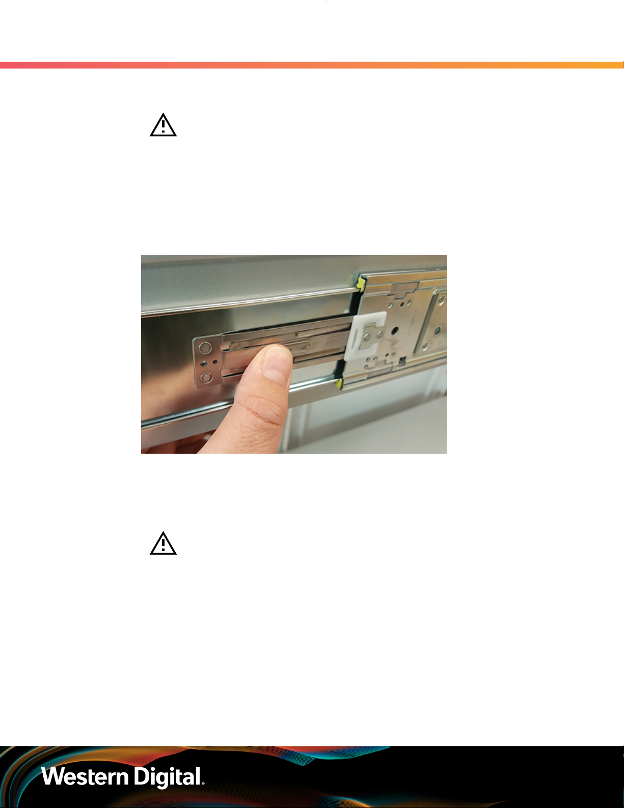
User Guide
3.7 CMA Replacement
b. Grasp both handles at the front of the enclosure and pull with even pressure until the
enclosure will not extend further.
Warning: The handles on the front of the chassis are not intended to be used
to support the weight of the Ultrastar Data60 . Lifting the unit by the chassis
handles or trying to support the unit on the handles can cause them to fail.
This can cause serious damage to the unit or serious bodily harm to those
handling the unit. Always team lift the chassis by gripping the underside of the
unit, and never try to lift a chassis that is filled with drives.
Locate the safety catches on the inner rails attached to the enclosure.
c.
Figure 71: Safety Latch Release
3. Support
d. Depress the latch release lever for the safety latches on the rail and push the chassis very
slightly forward. The chassis is now unsecured from the rack.
e.
Ensure that you have the proper support mechanism to hold the chassis in position, whether
that be a team lifting partner or an appropriate lift.
Warning: Do not lift the chassis by the Cable Tray while removing the chassis
from the rack OR while installing it into a rack. This can cause serious damage
to the unit or serious bodily harm to those handling the unit. Always team lift
the chassis by gripping the underside of the unit, and never try to lift a chassis
that is filled with drives.
f. Slide the chassis forward to free it from the rails. Place the chassis in a safe location to avoid
damage.
Step 11 : Install the chassis into the rails.
a. Extend the bearing plates on the inside of the mid-rails until they are fully forward (detent
has engaged). This prevents potential damage due to improper mating of the rails.
80
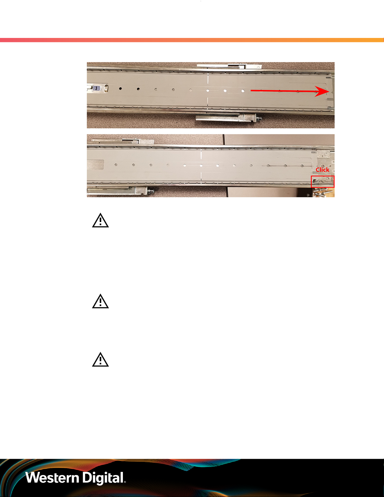
User Guide
3. Support
3.7 CMA Replacement
Figure 72: Bearing Plate
b.
Caution: This step in the installation requires a minimum of 3 individuals to
install safely, two to lift and one to guide the others who may have difficulty
seeing because the enclosure is in the way. Ensure that the appropriate
measures are taken to safely support the enclosure during installation. The
enclosure MUST have no drives installed and requires a two person team lift to
install. Do not attempt to lift the system if it is fully populated with drives.
The only case in which the system may be installed or removed with the drives
populated is if the facility has a lift that is rated to handle the maximum weight
of the fully loaded system.
Warning: The handles on the front of the chassis are not intended to be used
to support the weight of the Ultrastar Data60 . Lifting the unit by the chassis
handles or trying to support the unit on the handles can cause them to fail. This
can cause serious damage to the unit or serious bodily harm to those handling
the unit. Always team lift the chassis by gripping the underside of the unit, and
never try to lift a chassis that is filled with drives.
Warning: Do not lift the chassis by the Cable Tray while removing the chassis
from the rack OR while installing it into a rack. This can cause serious damage
to the unit or serious bodily harm to those handling the unit. Always team lift
the chassis by gripping the underside of the unit, and never try to lift a chassis
that is filled with drives.
In preparation to perform a team lift, position one individual on each side of the enclosure
(to lift) and a third individual standing at the protruding rack rails (to guide the chassis to
mate with rack rails).
Team-lift the enclosure until the inner rails (which are attached to the chassis) align with the
c.
extended mid-rails (which are attached to the rack), and guide the inner rails on the chassis
to mate with the rack rails.
81

User Guide
3. Support
3.7 CMA Replacement
Figure 73: Installing the Chassis
d.
Once the rails are mated properly, slide the enclosure into the rack until it is stopped by the
safety catch on the rails. Push the release lever on the safety latch (located on the side of
each of the rails), and push the enclosure the rest of the way into the rack.
Figure 74: Safety Latch Release
e. As the chassis is slid into the rack, position one installer at the rear of the rack to ensure that
the pegs on the sides of the cover will slide correctly into the rear cover alignment brackets
on both sides of the rack. If the chassis does not install smoothly or snags, check that the
rear cover alignment brackets are not interfering with the chassis sidewalls, and try again.
Step 12 : Install the CMA(s).
82

User Guide
3.7 CMA Replacement
Note: The CMA has two arms, labeled "upper" and "lower." The lower arm should
have the elbow on the left side and be installed first; the upper arm should have
the elbow on the right side and be installed last.
a. Orient the CMA so that the elbow is on the left hand side.
Attach all three of the connectors to the brackets on the rails. There should be one at the
b.
elbow side and two at the other end.
Figure 75: Lower CMA Orientation
3. Support
c. Slowly slide the enclosure forward to ensure the arm is operating properly, then slide it back
into the rack.
a. Repeat these steps to install the upper arm with the elbow facing to the right.
Step 13 : Cable the CMA(s).
a. Unlatch the elbow side of the arm(s) by pressing the blue button labeled “push,” and then
swing the arm(s) open.
Gather the SAS, power, and Ethernet cables for installation. Before cabling, note the
b.
following routing patterns for best results:
Note: Route the cables supported by the lower arm to IOM A (left hand side
looking at the rear). Second, route the cables supported by the upper arm to
IOM B (right hand side looking at the rear) in a "criss-cross" pattern. See the
Special Considerations for Cable Routing (page 154) for more information.
83

User Guide
3. Support
3.7 CMA Replacement
Figure 76: CMA Cable Routing
c.
Open all of the baskets.
Figure 77: Open Baskets
84

User Guide
3. Support
3.7 CMA Replacement
d. Connect the Ethernet cable to the Ethernet port, and route the cable through each of the
baskets on the arm.
e. Connect the SAS cables to the SAS ports, and route them through the baskets one at a time.
Make sure to follow the labels to ensure they are connected to the proper ports.
Connect the power cable to the PSU and route it through each basket.
f.
Attention: Make sure the power cable is not connected to a PDU. If it is,
the system will power up when the cable is connected to a PSU. This is not
intended at this stage of installation.
If the installation includes more than 10 total cables, follow the recommendations in Special
g.
Considerations for Cable Routing (page 154), before proceeding.
Note: Each cable must be given enough slack at the connector end to operate
smoothly. Allow 20 - 21 in. (508 – 533.4 mm) between the connector and the
first basket.
Figure 78: Nominal Cable Length at Connectors
h. Close all of the baskets.
i. If the Ultrastar Data60 is being installed in a rack and will subsequently be transported
inside that rack, it is important to use the included cable tie to wrap the CMA bundle to
ensure it does not get damaged during transport. If the Ultrastar Data60 is instead being
installed where it will be operated, skip this step. Remember to remove the cable ties after
the enclosure has reached its final operational location.
j. Reconnect the arm at the elbow to the connectors on the rail.
85
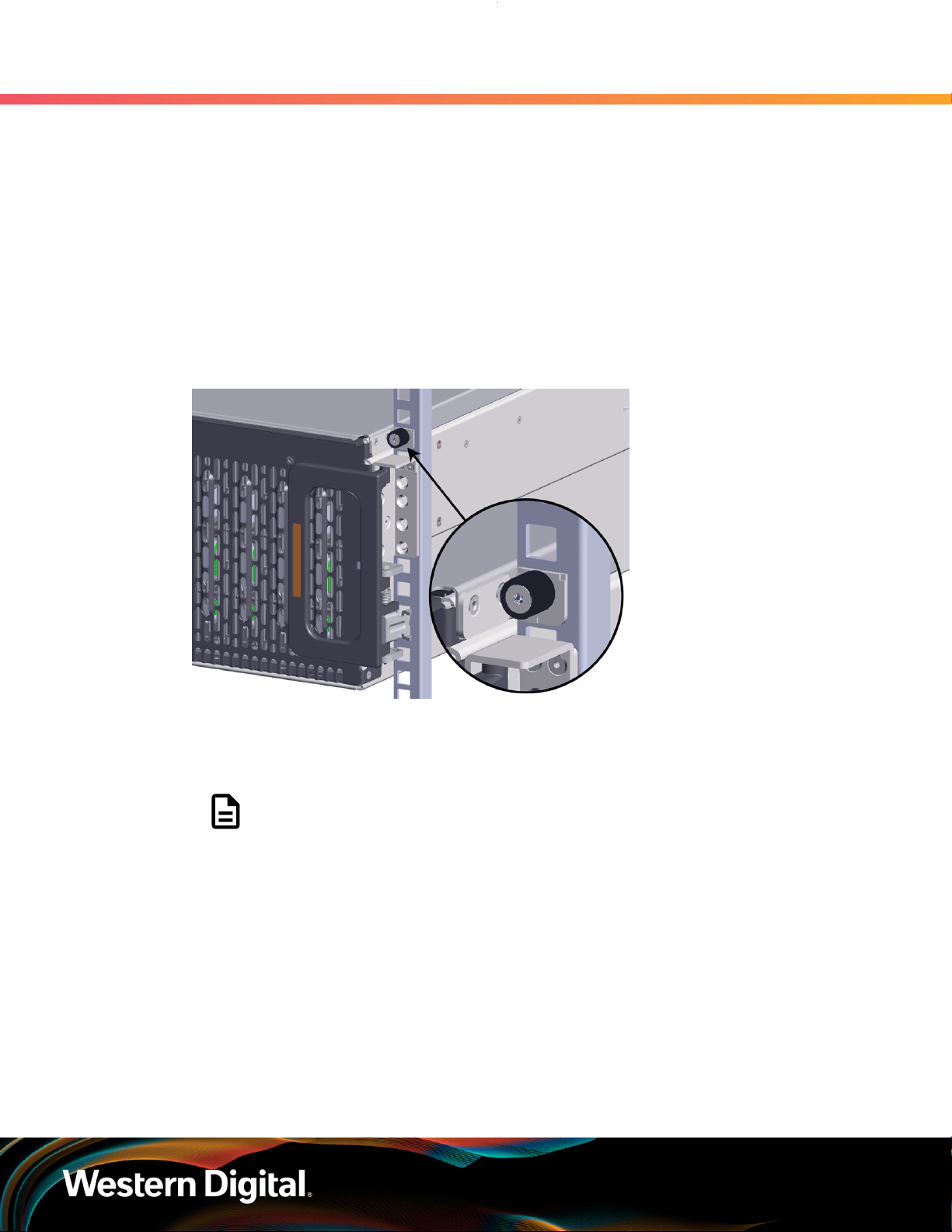
User Guide
Step 14 : Make sure the CMA(s) is in operational position by folding the arm(s) in toward the enclosure and
Step 15 :
Step 16 : Secure the chassis top cover to the rack using the captive M5 thumb-screws as shown in the
3. Support
3.7 CMA Replacement
attaching the elbow end(s) to the connector(s) attached to the rail. Verify that all of the cabling is
in functional order and does not bind or catch.
Test for binding in the extension of the arm by gently pulling the enclosure out of the rack,
ensuring the cables extend properly and that the system doesn’t bind at all. If it does, examine
the point at which the binding occurred and adjust the seating of cables in the baskets, check
the connections to the rails, and examine the joints of the arm to ensure that they are all
functioning properly.
following image. Use a T15 Torx screwdriver, and tighten the screws to 3.38-3.61 Nm / 30-32 inlbf.
Figure 79: Cover Retention Screws
Step 17 : Now that the chassis is installed, test the installation by sliding the enclosure in and out of the
rack a minimum of three times. If the enclosure binds, catches, or displays any incorrect motion
or behavior repeat the installation.
Note: Adjustments of the vertical rack rails may be required to fix any issues that
may occur.
Step 18 : Grasp both handles at the front of the enclosure and pull with even pressure to extend the
chassis out of the rack until it is stopped by the safety latches. The safety latches will prevent the
enclosure from coming out of the rack completely and the cover will remain in the rack attached
to the rear alignment brackets.
86

User Guide
3. Support
3.7 CMA Replacement
Figure 80: Chassis Handle Operation
Step 19 :
Step 20 : Install the 3.5in HDD Assembly.
Perform this same action two more times without the drives loaded to make sure the rail kits are
installed properly.
Note: The 2.5in SSD Assembly is installed in the same manner as the 3.5in HDD
Assembly. For instructions on assembling the 2.5in SSD Assembly, see Operating
the 2.5" Drive Carrier (page ).
a. Ensure that the enclosure has been pulled out of the rack until the rail latches engage.
Find the LED pointer on the top of the drive carrier. This pointer should point toward the
b.
front of the unit as shown in the following image.
87

User Guide
3. Support
3.7 CMA Replacement
Figure 81: LED Pointer Orientation
c. Align the drive with the empty slot that will receive it. Lower it into the slot, making sure it
stays level and does not snag.
88
 Loading...