

Page 1

Installation Guide
Ultrastar Data60
Regulatory Model: H4060-J
December 2020
Rev. 1.15
1ET1105
Page 2

Installation Guide Table of Contents
Table of Contents
Revision History.....................................................................................................................................iii
Notices....................................................................................................................................................v
Points of Contact.................................................................................................................................. vi
Product Label Information............................................................................................................. vi
Chapter 1. Overview.........................................................................................................1
Ultrastar Data60 Description............................................................................................................... 2
Ultrastar Data60 Layout....................................................................................................................... 2
Environmental Specifications...............................................................................................................4
Electrical Specifications....................................................................................................................... 4
Mechanical Specifications....................................................................................................................5
Performance Specifications................................................................................................................. 5
Ultrastar Data60 Rack Requirements..................................................................................................6
Compatible Rack Hardware Configuration................................................................................. 7
List of Compatible Drives....................................................................................................................9
Chapter 2. Disclaimers.................................................................................................. 20
Restricted Access Location............................................................................................................... 21
Safety Compliance..............................................................................................................................21
Electromagnetic Compatibility (EMC) Class A Compliance............................................................21
Country Certifications........................................................................................................................ 22
Chapter 3. Safety........................................................................................................... 23
Safety Warnings and Cautions.......................................................................................................... 24
Electrostatic Discharge......................................................................................................................24
Optimizing Location...........................................................................................................................24
Power Connections............................................................................................................................25
Power Cords.......................................................................................................................................25
Rackmountable Systems....................................................................................................................25
i
Page 3

Installation Guide Table of Contents
Safety and Service............................................................................................................................. 26
Chapter 4. Packaging....................................................................................................27
Ultrastar Data60 Packaging Overview..............................................................................................28
Ultrastar Data60 Unpacking Procedure.............................................................................................31
Chapter 5. Installation...................................................................................................34
Ultrastar Data60 Installation Overview............................................................................................. 35
Ultrastar Data60 Installation Procedure............................................................................................35
Operating the 2.5" Drive Carrier............................................................................................... 56
SAS Cabling........................................................................................................................................ 58
Special Considerations for Cable Routing.......................................................................................60
Cabling for CMA.................................................................................................................................62
Before You Begin........................................................................................................................ 62
Cabling CMA............................................................................................................................... 63
ii
Page 4

Installation Guide Revision History
Revision History
Date Revision Comment
November 2017 1.0 Initial release
November 2017 1.1
December 2017 1.2
January 2018 1.2.1 Updated the product name
January 2018 1.2.2 Added an image for cage nut positioning in the installation procedure.
January 2018 1.3
• The crossbar on the CMA was changed. See the installation
instructions for details.
• Changed required rack depth, see Required Rack Depth (page
5).
• Changed typical power consumption, see Typical Power
Consumption (page 4).
• Added active cable support
• Added a note regarding single IOMs in SATA TLAs. See Ultrastar
Data60 Description (page 2)
• Updated the Non-Op altitude specification. See Non-Operational
Altitude (page 4).
• Correct the packaging images to show the two CMA boxes that
come in the accessory tray. See Packaging Layout (page 28).
• Updated information on the 2.5" drive carrier option. (topic
removed)
• Added torque requirements for all screws used in the enclosure.
• Updated the IOM replacement section to account for the possibility
of a firmware mismatch. (topic removed)
• Updated the drive assembly installation instructions to clarify the
orientation of the drive assemblies. See Ultrastar Data60 Installation
Procedure (page 35).
April 2018 1.4
June 2018 1.5
December 2018 1.6
March 2019 1.7 Updated the Ultrastar Data60 Installation Procedure (page 35)
May 2019 1.8 Updated the Ultrastar Data60 Installation Procedure (page 35)
• Updated Compatible Drives List. See List of Compatible Drives
(page 9).
• Updated the Rack Requirements. See Ultrastar Data60 Rack
Requirements (page 6).
• Updated the Compatible Drives List. See List of Compatible Drives
(page 9)
• Updated Compatible Drives List. See List of Compatible Drives
(page 9)
iii
Page 5

Installation Guide Revision History
Date Revision Comment
July 2019 1.9
• Updated servicing image to correct length values and rail servicing
extension in Ultrastar Data60 Rack Requirements (page 6)
section.
• Updated revision history to remove broken links to topics no longer
in this document.
November 2019 1.10
December 2019 1.11
April 2020 1.12
August 2020 1.13 Updated SAS Cabling (page 58)
October 2020 1.14
• Replaced references to He12 drives with Ultrastrar DC HC520 in List
of Compatible Drives (page 9)
• Corrected layout image annotations to match table numbering in
Ultrastar Data60 Layout (page 2)
• Updated images of chassis cover screws throughout
• Rebranded document to WD design
• Updated the List of Compatible Drives (page 9)
• Updated drive installation order in the Ultrastar Data60 Installation
Procedure (page 35)
• Added SAS Cabling (page 58)
• Added note about minimum time between removing and
reapplying power in Power Connections (page 25)
• Updated images and text in Ultrastar Data60 Packaging Overview
(page 28) and Ultrastar Data60 Unpacking Procedure (page
31)
•
Added the following to Ultrastar Data60 Installation Procedure
(page 35):
December 2020 1.15
◦ Note about input voltage at plug-in step
◦ Reference to User Guide after installation instructions
◦ Note about installation of 2.5in SSD Assembly
• Added Operating the 2.5" Drive Carrier (page 56)
• Updated table of approved SAS cables in SAS Cabling (page 58)
• Reordered cabling topics in Installation (page 34) section
• Added UK Import Representation Contact
• Removed Formerica cables from SAS Cabling (page 58)
iv
Page 6

Installation Guide Notices
Notices
Western Digital Technologies, Inc. or its affiliates' (collectively “Western Digital”) general policy does not
recommend the use of its products in life support applications wherein a failure or malfunction of the product
may directly threaten life or injury. Per Western Digital Terms and Conditions of Sale, the user of Western
Digital products in life support applications assumes all risk of such use and indemnifies Western Digital
against all damages.
This document is for information use only and is subject to change without prior notice. Western Digital
assumes no responsibility for any errors that may appear in this document, nor for incidental or consequential
damages resulting from the furnishing, performance or use of this material.
Absent a written agreement signed by Western Digital or its authorized representative to the contrary,
Western Digital explicitly disclaims any express and implied warranties and indemnities of any kind that may,
or could, be associated with this document and related material, and any user of this document or related
material agrees to such disclaimer as a precondition to receipt and usage hereof.
Each user of this document or any product referred to herein expressly waives all guaranties and warranties
of any kind associated with this document any related materials or such product, whether expressed or
implied, including without limitation, any implied warranty of merchantability or fitness for a particular
purpose or non-infringement. Each user of this document or any product referred to herein also expressly
agrees Western Digital shall not be liable for any incidental, punitive, indirect, special, or consequential
damages, including without limitation physical injury or death, property damage, lost data, loss of profits or
costs of procurement of substitute goods, technology, or services, arising out of or related to this document,
any related materials or any product referred to herein, regardless of whether such damages are based on
tort, warranty, contract, or any other legal theory, even if advised of the possibility of such damages.
This document and its contents, including diagrams, schematics, methodology, work product, and
intellectual property rights described in, associated with, or implied by this document, are the sole and
exclusive property of Western Digital. No intellectual property license, express or implied, is granted by
Western Digital associated with the document recipient's receipt, access and/or use of this document or the
products referred to herein; Western Digital retains all rights hereto.
Western Digital, the Western Digital logo, and Ultrastar are registered trademarks or trademarks of Western
Digital Corporation or its affiliates in the US and/or other countries. Linux® is the registered trademark of
Linus Torvalds in the U.S. and other countries. All other marks are the property of their respective owners.
Product specifications subject to change without notice. Pictures shown may vary from actual products. Not
all products are available in all regions of the world.
Western Digital
5601 Great Oaks Parkway
San Jose, CA 95119
© 2020 Western Digital Corporation or its affiliates. All Rights Reserved.
v
Page 7
Installation Guide Points of Contact
Points of Contact
For further assistance with a Western Digital product, contact Western Digital Datacenter Platforms technical
support. Please be prepared to provide the following information: part number (P/N), serial number (S/N),
product name and/or model number, and a brief description of the issue.
Email:
support@wdc.com
Website:
https://portal.wdc.com/Support/s/
UK Import Representation Contact
Western Digital UK Limited Hamilton House, Regent Park, Kingston Road Leatherhead, Surrey KT22 7PL, GB,
United Kingdom
Telephone: +44 1372 366000
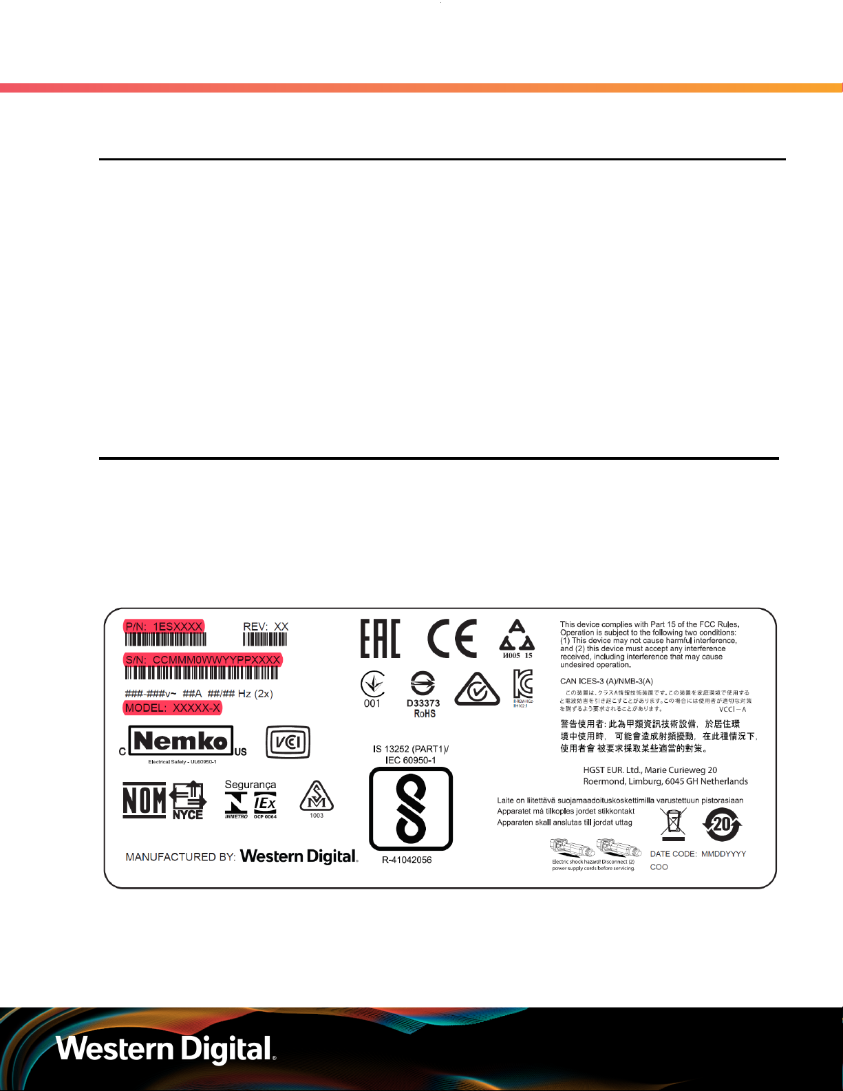
1.1 Product Label Information
The following product information is required for technical support requests:
• Part Number (P/N)
• Serial Number (S/N)
• Product Name and/or Model Number (MODEL)
This information may be found on the product label, which is affixed to an exterior, non-removable surface of
the chassis. The following is an example label with the applicable information fields highlighted:
vi
Page 8

Western Digital
Overview
This section provides a high level overview of the features of the
Ultrastar Data60 .
In This Chapter:
- Ultrastar Data60 Layout................................ 2
- Environmental Specifications........................2
- Electrical Specifications................................ 4
- Mechanical Specifications............................. 4
- Performance Specifications...........................5
- Ultrastar Data60 Rack Requirements........... 5
- List of Compatible Drives..............................6
1
Page 9
Installation Guide
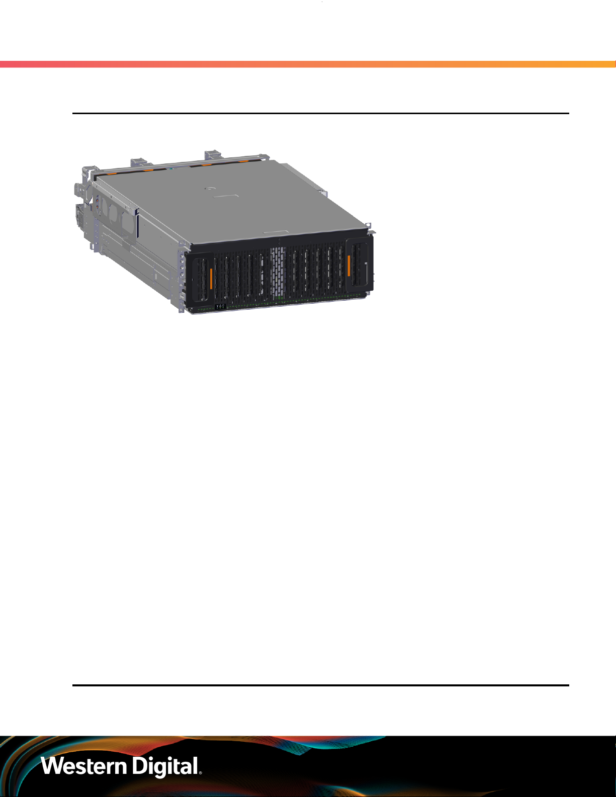
1.1 Ultrastar Data60 Description
Figure 2: Ultrastar Data60
1. Overview
1.1 Ultrastar Data60 Description
The Ultrastar Data60 is a 4U form factor, high availability, high density, rack-mounted storage enclosure
that is capable of hosting up to 60 SAS or SATA drives. The maximum data storage capacity of the Ultrastar
Data60 is 840 TB using 14TB HGST Ultrastar® HC530 drives . (For a full list of compatible drives and total
storage capacities, see the List of Compatible Drives (page 9).) The enclosure runs on an input voltage
of 200 - 240 VAC and consumes ~1000W of power under typical conditions. It requires a maximum of
~1250W at full load.
It is designed to fit within a 4U rack space and requires 900mm (35.43in.) usable rack space, frame to frame.
A fully loaded system will add 79.4 kg. / 175 lbs. of static load when fully loaded with drives.
• 4U Storage Enclosure
• Supports up to 60 Drives
• Can support 3.5” drives and 2.5” SSD drives (2.5" requires an adapter) in the 60 available drive bays.
• Up to 12W per drive slot for the 60 data storage drives (Cannot exceed 85A on the 5V rail)
• House and control four (4) N+1 redundant 80mm rear fans
• House and control a dual rotor 40mm internal IOM Fan
• Controlled by two (2) redundant I/O Modules
• Powered by two (2) redundant 1600W PSUs
• Supports High Line (220-240 VAC) Input Power
• Full high availability with independent dual paths to all HDDs
• Toolless replacement of all Customer Replaceable Units (CRUs)
• Fits within a standard EIA-310 rack including all necessary cable management (see Compatible Rack
Hardware Configuration (page 7))
• Supports up to 3m passive SAS cables (limited to 3m or less) or active cables (any length) (see SAS
Cabling (page 58))
1
1.2 Ultrastar Data60 Layout
1. SATA based models will only include 1 IOM
2
Page 10
Installation Guide
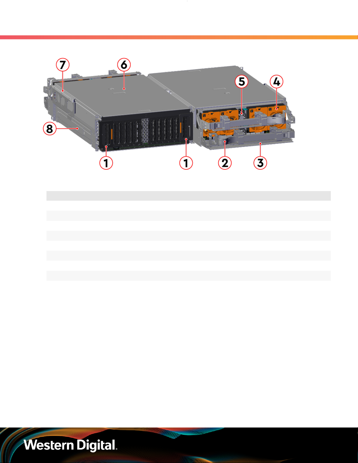
Figure 3: Front and Rear Product Layout
Table 1: Front and Rear Component Identification
1. Overview
1.2 Ultrastar Data60 Layout
Number Component
1 Enclosure Handles
2 CMAs
3 CMA Tray
4 Rear Fans
5 PSUs
6 Chassis Cover
7 Rear Cover Alignment Brackets
8 Rails
The following is an image of the layout of the major system components inside the Ultrastar Data60 .
3
Page 11
Installation Guide
Figure 4: Component Layout
1. Overview
1.3 Environmental Specifications
1.3 Environmental Specifications
Table 2: Environmental Specification Summary
Specification Non-Operational Operational
Temperature -40°C to 70°C 5°C to 35°C
Temperature Gradient 30°C / Hr 20°C per hour maximum
Temperature De-rating 1°C per 300m above 3000m 1°C per 300m above 900m
Relative Humidity 8-90% Non-Condensing 8-90% Non-Condensing
Relative Humidity Gradient 30% per hour maximum 30% per hour maximum
Altitude -300m to 12,000m /
-984 ft. to 39,370 ft
1.4 Electrical Specifications
Table 3: Electrical Specifications
Specification Value
Max Power Consumption ~1250W
Typical Power Consumption
2
-300m to 3048m /
-984 ft. to 10,000 ft.
~1000W
Input Voltage 200 - 240 VAC
PSU Connector Type C14
PSU Efficiency 80 PLUS Platinum
2. Max and typical power consumption values represent the output power to the system. Input power will vary depending
on the PSU efficiency and load sharing between PSUs.
4
Page 12

Installation Guide
Specification Value
Inrush Current Maximum (per
PSU)
Caution: The Ultrastar Data60 can only be plugged into high line (200 - 240 VAC) power. If
the unit is plugged into low line (110-127 VAC), the PSU will report a "Critical" state when status
pages are queried using SES. In this case, the enclosure will power up, but the drives will not.
The enclosure will remain in low-power mode.
AC line inrush current shall not exceed 40A peak, for up to
one-quarter of the AC cycle after which, the input current
should be no more than the specified maximum input current.
1.5 Mechanical Specifications
Table 4: Mechanical Specifications
Specification Non-Operational Operational
Shock 10G, 0 - peak,11ms half sine;
3 positive and 3 negative
pulses in each axis Shock
1. Overview
1.5 Mechanical Specifications
5G, 0 - peak, 11ms half sine; 3 positive
and 3 negative pulses in each axis-
minimum 6 seconds between shocks
to allow for write/read recovery
Vibration 0.75G, 0 - peak swept sine;
5 -500Hz; 1 complete sweep
@ 1/2 octave per minute
Weight 79.4 kg. / 175 lbs.
Dimensions 447mm x 890mm x 175mm / 17.67in. x 35.04in. x 6.89in.
Length without CMA 712 mm / 28.03in.
Required Rack Width 450mm (17.72in.) with 465mm (18.31in.) ± 1.5mm
nominal hole spacing. See EIA-310 Rack Standard
Required Rack Depth 900mm (35.43in.) usable rack space, frame to frame
Rack Units (U) 4U
Vertical Rack Rail
Spacing
1.6 Performance Specifications
Table 5: Performance Specifications
Specification Value
Number of Drive Slots 60
0.10G,0 - peak swept sine; 5
-500Hz; 1 complete sweep
@ 1/2octave per minute
24 in. - 32 in.
Data Transfer Rates 12Gbps SAS / 6Gbps SATA
Max Raw Data Storage Capacity 840 TB using 14TB HGST Ultrastar® HC530 drives
SAS Ports 12 x Mini-SAS HD ( 6 per IOM)
5
Page 13

Installation Guide
Specification Value
1.7 Ultrastar Data60 Rack Requirements
2 x 10/100/1G Ethernet
1.7 Ultrastar Data60 Rack Requirements
The Ultrastar Data60 is designed to be installed into a rack that meets the EIA-310 standard at a minimum
900mm (35.43in.) usable rack space, frame to frame. The vertical rack rails must be set between 24 in. 32 in. to support the enclosure. It requires 4U of rack space, and it should be installed into the rack at the
lowest possible U height to keep the load on the rack balanced.
Table 6: Required Rack Specifications
Parameter Requirement
Rack Depth 900mm (35.43in.) usable rack space, frame to frame
1. Overview
Rack Width
Rack Units (U) 4U
Vertical Rack Rail Spacing 24 in. - 32 in.
Static Load Rating 1360.7 kg. / 3000 lbs.
Dynamic Load Rating 1020.5 kg. / 2250 lbs.
Warning: When extended out of the rack on the rail system, the Ultrastar Data60 will be
~630mm / 24.8in. extended outward. This may be a potential tipping hazard depending on
the configuration of the rack. Ensure that leveling feet, anti-tilt, and any other safety features
recommended by the specific rack manufacturers have been deployed before servicing.
The following section provides specific information necessary to install, service, and remove the Ultrastar
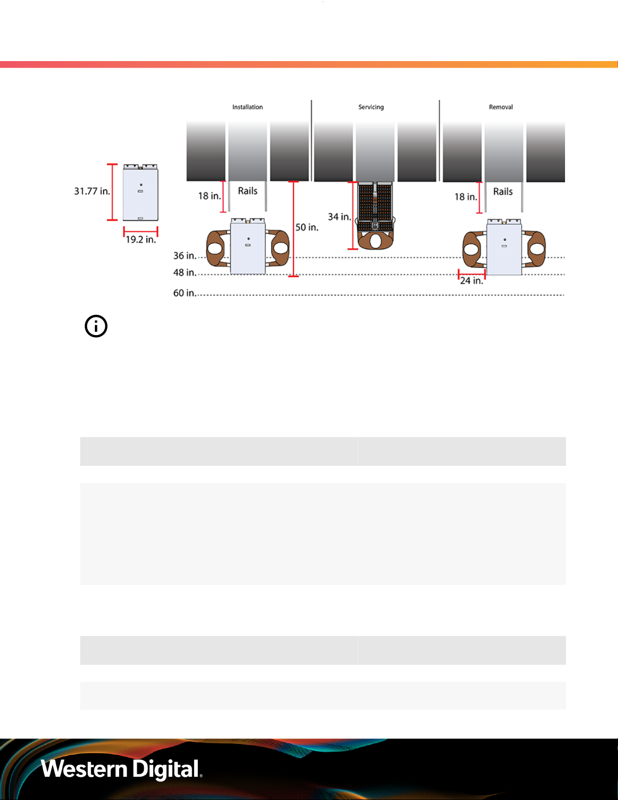
Data60 . The installation of the Ultrastar Data60 requires two people and a space of 1270mm / 50in.
in front of the installation space. The servicing of the enclosure requires one person and a minimum of
863.6mm / 34in. of space in front of the installation space. The removal of the enclosure requires two
people, 914.4mm / 36in. of space in front of the installation space, and 24in. on either side of the enclosure
for two people to remove the enclosure.
Warning: The handles on the front of the chassis are not intended to be used to support the
weight of the Ultrastar Data60 . Lifting the unit by the chassis handles or trying to support the
unit on the handles can cause them to fail. This can cause serious damage to the unit or serious
bodily harm to those handling the unit. Always team lift the chassis by gripping the underside
of the unit, and never try to lift a chassis that is filled with drives.
450mm (17.72in.) with 465mm (18.31in.) ± 1.5mm
nominal hole spacing. See EIA-310 Rack Standard
6
Page 14
Installation Guide
Figure 5: Installation, Servicing, and Removal
1. Overview
1.7 Ultrastar Data60 Rack Requirements
Attention: Do not install or remove the enclosure while it is populated with drives. The fully
populated enclosure exceeds the amount of weight that a team of two should lift.
1.7.1 Compatible Rack Hardware Configuration
The following table(s) list the approved rack hardware configurations for the Ultrastar Data60 :
Table 7: Compatible Hardware Configuration 1
Parameter Rack PDU (Vertical)
Vendor CRENLO/EMCOR Server Technology Server Technology Various
AS-160099-03
(Drawing
Number EMCOR
Part
Number
Quantity 1 2 2 Varies
526121 Rev 5)
412-0761-11_STV-4501
412-0761-20_STV-4502
412-0761-23_STV-4503
PDU Mounting
Bracket
KIT-MBVPT-1B
(one kit per PDU)
Additional Mounting
Bracket Hardware
4 x M6 x 16 Hex
Cap Screws
8 x M6 Fender
4 x M6 Hex Nut
with Nylon Lock
Washers
Table 8: Compatible Hardware Configuration 2
Parameter Rack PDU (Vertical)
Vendor AFCO/Legrand Server Technology Server Technology Various
Part
Number
Options:
412-0761-11_STV-4501
PDU Mounting
Bracket
KIT-MB-40 None
Additional Mounting
Bracket Hardware
7
Page 15

Installation Guide
1. Overview
1.7 Ultrastar Data60 Rack Requirements
Parameter Rack PDU (Vertical)
42RU –
WEDIT605
45RU –
WEDIT604
48RU –
WEDIT603
51RU –
WEDIT606
Quantity 1 rack 2 1 N/A
412-0761-20_STV-4502
412-0761-23_STV-4503
PDU Mounting
Bracket
Additional Mounting
Bracket Hardware
Table 9: Compatible Hardware Configuration 3
Parameter Rack PDU (Vertical)
Vendor TRIPP LITE Server Technology Server Technology Various
Options:
SR42UBDP (Rack)
412-0761-11_STV-4501
412-0761-20_STV-4502
PDU Mounting
Bracket
KIT-MBVPT-1B None
Additional Mounting
Bracket Hardware
SREXTENDER
25U (Rack
Part
Number
Quantity 1 rack 2 1 N/A
Extension)
SREXTENDER
42U (Rack
Extension)
SREXTENDER
48U (Rack
Extension)
412-0761-23_STV-4503
Table 10: Compatible Hardware Configuration 4
Parameter Rack PDU (Vertical)
Vendor APC/Schneider Server Technology Server Technology Various
AR3300W
Part
Number
412-0761-11_STV-4501
412-0761-20_STV-4502
412-0761-23_STV-4503
PDU Mounting
Bracket
KIT-MBVPT-1B
(one kit per PDU)
Additional Mounting
Bracket Hardware
4 x M6 x 16 Hex
8 x M6 Fender
Cap Screws
Washers
4 x M6 Hex Nut
with Nylon Lock
8
Page 16

Installation Guide
1. Overview
1.8 List of Compatible Drives
Parameter Rack PDU (Vertical)
Quantity 1 rack 2 2 Varies
1.8 List of Compatible Drives
HDD with 3.5-inch Drive Carrier
Table 11: Western Digital Ultrastar DC HC310
Drive Type Interface
Ultrastar DC HC310
w/ 3.5 in. drive carrier
Ultrastar DC HC310
w/ 3.5 in. drive carrier
Ultrastar DC HC310
w/ 3.5 in. drive carrier
Ultrastar DC HC310
w/ 3.5 in. drive carrier
HDD SATA 6Gb/s 512e SE 6TB 1EX1189
HDD SATA 6Gb/s 512e TCG 6TB 1EX1188
HDD SATA 6Gb/s 4Kn SE 6TB 1EX1187
HDD SATA 6Gb/s 4Kn TCG 6TB 1EX1186
PDU Mounting
Sector
Size
Additional Mounting
Bracket
Encryption Volume Part Number
Bracket Hardware
Ultrastar DC HC310
w/ 3.5 in. drive carrier
Ultrastar DC HC310
w/ 3.5 in. drive carrier
Ultrastar DC HC310
w/ 3.5 in. drive carrier
Ultrastar DC HC310
w/ 3.5 in. drive carrier
Ultrastar DC HC310
w/ 3.5 in. drive carrier
Ultrastar DC HC310
w/ 3.5 in. drive carrier
HDD SAS 12Gb/s 512e SE 6TB 1EX1185
HDD SAS 12Gb/s 512e TCG 6TB 1EX1184
HDD SAS 12Gb/s 512e TCG-FIPS 6TB 1EX1853
HDD SAS 12Gb/s 4Kn SE 6TB 1EX1183
HDD SAS 12Gb/s 4Kn TCG 6TB 1EX1182
HDD SAS 12Gb/s 4Kn TCG-FIPS 6TB 1EX1852
Table 12: Western Digital Ultrastar DC HC320
Drive Type Interface
Ultrastar DC HC320
w/ 3.5 in. drive carrier
Ultrastar DC HC320
w/ 3.5 in. drive carrier
HDD SATA 6Gb/s 512e SE 8TB 1EX1227
HDD SATA 6Gb/s 512e SED 8TB 1EX1226
Sector
Size
Encryption Volume Part Number
Ultrastar DC HC320
w/ 3.5 in. drive carrier
Ultrastar DC HC320 HDD SATA 6Gb/s 4Kn TCG 8TB 1EX1224
HDD SATA 6Gb/s 4Kn SE 8TB 1EX1225
9
Page 17

Installation Guide
1. Overview
1.8 List of Compatible Drives
Drive Type Interface
w/ 3.5 in. drive carrier
Ultrastar DC HC320
w/ 3.5 in. drive carrier
Ultrastar DC HC320
w/ 3.5 in. drive carrier
Ultrastar DC HC320
w/ 3.5 in. drive carrier
Ultrastar DC HC320
w/ 3.5 in. drive carrier
Ultrastar DC HC320
w/ 3.5 in. drive carrier
Ultrastar DC HC320
w/ 3.5 in. drive carrier
HDD SAS 12Gb/s 512e SE 8TB 1EX1223
HDD SAS 12Gb/s 512e TCG 8TB 1EX1222
HDD SAS 12Gb/s 512e TCG-FIPS 8TB 1EX1343
HDD SAS 12Gb/s 4Kn SE 8TB 1EX1221
HDD SAS 12Gb/s 4Kn TCG 8TB 1EX1220
HDD SAS 12Gb/s 4Kn TCG-FIPS 8TB 1EX1342
Table 13: Western Digital Ultrastar DC HC330
Drive Type Interface
Ultrastar DC HC330
w/ 3.5 in. drive carrier
HDD SATA 6Gb/s 512e SE 10TB 1EX2440
Sector
Size
Sector
Size
Encryption Volume Part Number
Encryption Volume Part Number
Ultrastar DC HC330
w/ 3.5 in. drive carrier
Ultrastar DC HC330
w/ 3.5 in. drive carrier
Ultrastar DC HC330
w/ 3.5 in. drive carrier
Ultrastar DC HC330
w/ 3.5 in. drive carrier
Ultrastar DC HC330
w/ 3.5 in. drive carrier
Ultrastar DC HC330
w/ 3.5 in. drive carrier
Ultrastar DC HC330
w/ 3.5 in. drive carrier
Ultrastar DC HC330
w/ 3.5 in. drive carrier
HDD SATA 6Gb/s 512e SED 10TB 1EX2441
HDD SATA 6Gb/s 4Kn SE 10TB 1EX2438
HDD SATA 6Gb/s 4Kn SED 10TB 1EX2439
HDD SAS 12Gb/s 512e SE 10TB 1EX2435
HDD SAS 12Gb/s 512e TCG 10TB 1EX2436
HDD SAS 12Gb/s 512e TCG-FIPS 10TB 1EX2437
HDD SAS 12Gb/s 4Kn TCG 10TB 1EX2433
HDD SAS 12Gb/s 4Kn TCG-FIPS 10TB 1EX2434
Table 14: Western Digital Ultrastar DC HC510
Drive Type Interface
Ultrastar DC HC510
w/ 3.5 in. drive carrier
HDD SATA 6Gb/s 512e SE 10TB 1EX0499
Sector
Size
Encryption Volume Part Number
10
Page 18

Installation Guide
1. Overview
1.8 List of Compatible Drives
Drive Type Interface
Ultrastar DC HC510
w/ 3.5 in. drive carrier
Ultrastar DC HC510
w/ 3.5 in. drive carrier
Ultrastar DC HC510
w/ 3.5 in. drive carrier
Ultrastar DC HC510
w/ 3.5 in. drive carrier
Ultrastar DC HC510
w/ 3.5 in. drive carrier
Ultrastar DC HC510
w/ 3.5 in. drive carrier
Ultrastar DC HC510
w/ 3.5 in. drive carrier
Ultrastar DC HC510
w/ 3.5 in. drive carrier
Ultrastar DC HC510
w/ 3.5 in. drive carrier
Sector
Size
HDD SATA 6Gb/s 512e ISE 10TB 1EX0497
HDD SATA 6Gb/s 512e SED 10TB 1EX0498
HDD SATA 6Gb/s 4Kn SE 10TB 1EX0496
HDD SATA 6Gb/s 4Kn ISE 10TB 1EX0494
HDD SATA 6Gb/s 4Kn SED 10TB 1EX0495
HDD SAS 12Gb/s 512e SE 10TB 1EX0487
HDD SAS 12Gb/s 512e ISE 10TB 1EX0485
HDD SAS 12Gb/s 512e TCG 10TB 1EX0486
HDD SAS 12Gb/s 512e TCG-FIPS 10TB 1EX1341
Encryption Volume Part Number
Ultrastar DC HC510
w/ 3.5 in. drive carrier
Ultrastar DC HC510
w/ 3.5 in. drive carrier
Ultrastar DC HC510
w/ 3.5 in. drive carrier
Ultrastar DC HC510
w/ 3.5 in. drive carrier
HDD SAS 12Gb/s 4Kn SE 10TB 1EX0484
HDD SAS 12Gb/s 4Kn ISE 10TB 1EX0482
HDD SAS 12Gb/s 4Kn TCG 10TB 1EX0483
HDD SAS 12Gb/s 4Kn TCG-FIPS 10TB 1EX1340
Table 15: Western Digital Ultrastar DC HC520
Drive Type Interface
Ultrastar DC HC520
w/ 3.5 in. drive carrier
Ultrastar DC HC520
w/ 3.5 in. drive carrier
Ultrastar DC HC520
w/ 3.5 in. drive carrier
Ultrastar DC HC520
w/ 3.5 in. drive carrier
HDD SATA 6Gb/s 512e SE 12TB 1EX1015
HDD SATA 6Gb/s 512e ISE 12TB 1EX1013
HDD SATA 6Gb/s 512e SED 12TB 1EX1014
HDD SATA 6Gb/s 4Kn SE 12TB 1EX1012
Sector
Size
Encryption Volume Part Number
Ultrastar DC HC520
w/ 3.5 in. drive carrier
Ultrastar DC HC520 HDD SATA 6Gb/s 4Kn SED 12TB 1EX1011
HDD SATA 6Gb/s 4Kn ISE 12TB 1EX1010
11
Page 19

Installation Guide
1. Overview
1.8 List of Compatible Drives
Drive Type Interface
w/ 3.5 in. drive carrier
Ultrastar DC HC520
w/ 3.5 in. drive carrier
Ultrastar DC HC520
w/ 3.5 in. drive carrier
Ultrastar DC HC520
w/ 3.5 in. drive carrier
Ultrastar DC HC520
w/ 3.5 in. drive carrier
Ultrastar DC HC520
w/ 3.5 in. drive carrier
Ultrastar DC HC520
w/ 3.5 in. drive carrier
Ultrastar DC HC520
w/ 3.5 in. drive carrier
Ultrastar DC HC520
w/ 3.5 in. drive carrier
Sector
Size
HDD SAS 12Gb/s 512e SE 12TB 1EX1009
HDD SAS 12Gb/s 512e ISE 12TB 1EX1007
HDD SAS 12Gb/s 512e TCG 12TB 1EX1008
HDD SAS 12Gb/s 512e TCG-FIPS 12TB 1EX1338
HDD SAS 12Gb/s 4Kn SE 12TB 1EX1006
HDD SAS 12Gb/s 4Kn ISE 12TB 1EX1004
HDD SAS 12Gb/s 4Kn TCG 12TB 1EX1005
HDD SAS 12Gb/s 4Kn TCG-FIPS 12TB 1EX1339
Encryption Volume Part Number
Table 16: Western Digital Ultrastar DC HC530
Drive Type Interface
Ultrastar DC HC530
w/ 3.5 in. drive carrier
Ultrastar DC HC530
w/ 3.5 in. drive carrier
Ultrastar DC HC530
w/ 3.5 in. drive carrier
Ultrastar DC HC530
w/ 3.5 in. drive carrier
Ultrastar DC HC530
w/ 3.5 in. drive carrier
Ultrastar DC HC530
w/ 3.5 in. drive carrier
Ultrastar DC HC530
w/ 3.5 in. drive carrier
Ultrastar DC HC530
w/ 3.5 in. drive carrier
Ultrastar DC HC530
w/ 3.5 in. drive carrier
HDD SATA 6Gb/s 512e SE 14TB 1EX1793
HDD SATA 6Gb/s 512e SED 14TB 1EX1794
HDD SATA 6Gb/s 4Kn SE 14TB 1EX1790
HDD SAS 12Gb/s 512e SE 14TB 1EX1791
HDD SAS 12Gb/s 512e ISE 14TB 1EX1583
HDD SAS 12Gb/s 512e TCG 14TB 1EX1792
HDD SAS 12Gb/s 512e TCG-FIPS 14TB 1EX1855
HDD SAS 12Gb/s 4Kn SE 14TB 1EX1788
HDD SAS 12Gb/s 4Kn TCG 14TB 1EX1789
Sector
Size
Encryption Volume Part Number
Ultrastar DC HC530 HDD SAS 12Gb/s 4Kn TCG-FIPS 14TB 1EX1854
12
Page 20

Installation Guide
1. Overview
1.8 List of Compatible Drives
Drive Type Interface
w/ 3.5 in. drive carrier
Table 17: Western Digital Ultrastar DC HC550
Drive Type Interface
Ultrastar DC HC550
w/ 3.5 in. drive carrier
Ultrastar DC HC550
w/ 3.5 in. drive carrier
Ultrastar DC HC550
w/ 3.5 in. drive carrier
Ultrastar DC HC550
w/ 3.5 in. drive carrier
Ultrastar DC HC550
w/ 3.5 in. drive carrier
Ultrastar DC HC550
w/ 3.5 in. drive carrier
Ultrastar DC HC550
w/ 3.5 in. drive carrier
HDD SATA 6Gb/s 512e SE 16TB 1EX2476
HDD SATA 6Gb/s 512e SED 16TB 1EX2477
HDD SAS 12Gb/s 512e SE 16TB 1EX2473
HDD SAS 12Gb/s 512e TCG 16TB 1EX2474
HDD SAS 12Gb/s 512e TCG-FIPS 16TB 1EX2475
HDD SATA 6Gb/s 512e SE 18TB 1EX2481
HDD SATA 6Gb/s 512e SED 18TB 1EX2482
Sector
Size
Sector
Size
Encryption Volume Part Number
Encryption Volume Part Number
Ultrastar DC HC550
w/ 3.5 in. drive carrier
Ultrastar DC HC550
w/ 3.5 in. drive carrier
Ultrastar DC HC550
w/ 3.5 in. drive carrier
HDD SAS 12Gb/s 512e SE 18TB 1EX2478
HDD SAS 12Gb/s 512e TCG 18TB 1EX2479
HDD SAS 12Gb/s 512e TCG-FIPS 18TB 1EX2480
SSD with 2.5-inch Drive Carrier
Table 18: Western Digital Ultrastar SS300
Drive Type Interface Drive Writes Encryption Volume
Ultrastar SS300
w/ 2.5 in. drive carrier
Ultrastar SS300
w/ 2.5 in. drive carrier
Ultrastar SS300
w/ 2.5 in. drive carrier
Ultrastar SS300
w/ 2.5 in. drive carrier
SSD SAS 12Gb/s RI-3DW/D SE 400GB
SSD SAS 12Gb/s RI-3DW/D ISE 400GB
SSD SAS 12Gb/s RI-3DW/D TCG 400GB
SSD SAS 12Gb/s RI-3DW/D TCG-FIPS 400GB
Part
Number
No longer
available
No longer
available
No longer
available
No longer
available
Ultrastar SS300
w/ 2.5 in. drive carrier
SSD SAS 12Gb/s ME-10DW/D SE 400GB
No longer
available
13
Page 21

Installation Guide
1. Overview
1.8 List of Compatible Drives
Drive Type Interface Drive Writes Encryption Volume
Ultrastar SS300
w/ 2.5 in. drive carrier
Ultrastar SS300
w/ 2.5 in. drive carrier
Ultrastar SS300
w/ 2.5 in. drive carrier
Ultrastar SS300
w/ 2.5 in. drive carrier
Ultrastar SS300
w/ 2.5 in. drive carrier
Ultrastar SS300
w/ 2.5 in. drive carrier
Ultrastar SS300
w/ 2.5 in. drive carrier
Ultrastar SS300
w/ 2.5 in. drive carrier
Ultrastar SS300
w/ 2.5 in. drive carrier
SSD SAS 12Gb/s ME-10DW/D ISE 400GB
SSD SAS 12Gb/s ME-10DW/D TCG 400GB
SSD SAS 12Gb/s ME-10DW/D TCG-FIPS 400GB
SSD SAS 12Gb/s RI-3DW/D SE 800GB
SSD SAS 12Gb/s RI-3DW/D ISE 800GB
SSD SAS 12Gb/s RI-3DW/D TCG 800GB
SSD SAS 12Gb/s RI-3DW/D TCG-FIPS 800GB
SSD SAS 12Gb/s ME-10DW/D SE 800GB
SSD SAS 12Gb/s ME-10DW/D ISE 800GB
Part
Number
No longer
available
No longer
available
No longer
available
No longer
available
No longer
available
No longer
available
No longer
available
No longer
available
No longer
available
Ultrastar SS300
w/ 2.5 in. drive carrier
Ultrastar SS300
w/ 2.5 in. drive carrier
Ultrastar SS300
w/ 2.5 in. drive carrier
Ultrastar SS300
w/ 2.5 in. drive carrier
Ultrastar SS300
w/ 2.5 in. drive carrier
SSD SAS 12Gb/s ME-10DW/D TCG 800GB
SSD SAS 12Gb/s ME-10DW/D TCG-FIPS 800GB
SSD SAS 12Gb/s RI-3DW/D ISE 1.6TB
SSD SAS 12Gb/s RI-3DW/D TCG-FIPS 1.6TB
SSD SAS 12Gb/s ME-10DW/D TCG-FIPS 1.6TB
SSD with 3.5-inch to 2.5-inch Drive Carrier
Table 19: Western Digital Ultrastar SS200
Drive Type Interface Drive Writes Encryption Volume
Ultrastar SS200
w/ 3.5 in. to 2.5 in. drive carrier
Ultrastar SS200
w/ 3.5 in. to 2.5 in. drive carrier
SSD SAS 12Gb/s RI-3DW/D SE 400GB
SSD SAS 12Gb/s RI-3DW/D ISE 400GB
No longer
available
No longer
available
No longer
available
No longer
available
No longer
available
Part
Number
No longer
available
No longer
available
Ultrastar SS200
w/ 3.5 in. to 2.5 in. drive carrier
SSD SAS 12Gb/s RI-3DW/D TCG 400GB
No longer
available
14
Page 22

Installation Guide
1. Overview
1.8 List of Compatible Drives
Drive Type Interface Drive Writes Encryption Volume
Ultrastar SS200
w/ 3.5 in. to 2.5 in. drive carrier
Ultrastar SS200
w/ 3.5 in. to 2.5 in. drive carrier
Ultrastar SS200
w/ 3.5 in. to 2.5 in. drive carrier
Ultrastar SS200
w/ 3.5 in. to 2.5 in. drive carrier
Ultrastar SS200
w/ 3.5 in. to 2.5 in. drive carrier
Ultrastar SS200
w/ 3.5 in. to 2.5 in. drive carrier
Ultrastar SS200
w/ 3.5 in. to 2.5 in. drive carrier
Ultrastar SS200
w/ 3.5 in. to 2.5 in. drive carrier
Ultrastar SS200
w/ 3.5 in. to 2.5 in. drive carrier
SSD SAS 12Gb/s RI-3DW/D TCG-FIPS 400GB
SSD SAS 12Gb/s RI-1DW/D TCG 480GB
SSD SAS 12Gb/s RI-3DW/D SE 800GB
SSD SAS 12Gb/s RI-3DW/D ISE 800GB
SSD SAS 12Gb/s RI-3DW/D TCG 800GB
SSD SAS 12Gb/s RI-1DW/D TCG 960GB
SSD SAS 12Gb/s RI-3DW/D SE 1.6TB
SSD SAS 12Gb/s RI-3DW/D ISE 1.6TB
SSD SAS 12Gb/s RI-3DW/D TCG 1.6TB
Part
Number
No longer
available
No longer
available
No longer
available
No longer
available
No longer
available
No longer
available
No longer
available
No longer
available
No longer
available
Ultrastar SS200
w/ 3.5 in. to 2.5 in. drive carrier
Ultrastar SS200
w/ 3.5 in. to 2.5 in. drive carrier
Ultrastar SS200
w/ 3.5 in. to 2.5 in. drive carrier
Ultrastar SS200
w/ 3.5 in. to 2.5 in. drive carrier
SSD SAS 12Gb/s RI-1DW/D TCG 1.92TB
SSD SAS 12Gb/s RI-3DW/D ISE 3.2TB
SSD SAS 12Gb/s RI-1DW/D ISE 3.84TB
SSD SAS 12Gb/s RI-1DW/D SE 7.68TB
Table 20: Western Digital Ultrastar SS300
Drive Type Interface Drive Writes Encryption Volume
Ultrastar SS300
w/ 3.5 in. to 2.5 in. drive carrier
Ultrastar SS300
w/ 3.5 in. to 2.5 in. drive carrier
Ultrastar SS300
w/ 3.5 in. to 2.5 in. drive carrier
Ultrastar SS300
w/ 3.5 in. to 2.5 in. drive carrier
SSD SAS 12Gb/s RI-3DW/D SE 400GB
SSD SAS 12Gb/s RI-3DW/D ISE 400GB
SSD SAS 12Gb/s RI-3DW/D TCG 400GB
SSD SAS 12Gb/s ME-10DW/D SE 400GB
No longer
available
No longer
available
No longer
available
No longer
available
Part
Number
No longer
available
No longer
available
No longer
available
No longer
available
Ultrastar SS300
w/ 3.5 in. to 2.5 in. drive carrier
SSD SAS 12Gb/s ME-10DW/D ISE 400GB
No longer
available
15
Page 23

Installation Guide
1. Overview
1.8 List of Compatible Drives
Drive Type Interface Drive Writes Encryption Volume
Ultrastar SS300
w/ 3.5 in. to 2.5 in. drive carrier
Ultrastar SS300
w/ 3.5 in. to 2.5 in. drive carrier
Ultrastar SS300
w/ 3.5 in. to 2.5 in. drive carrier
Ultrastar SS300
w/ 3.5 in. to 2.5 in. drive carrier
Ultrastar SS300
w/ 3.5 in. to 2.5 in. drive carrier
Ultrastar SS300
w/ 3.5 in. to 2.5 in. drive carrier
Ultrastar SS300
w/ 3.5 in. to 2.5 in. drive carrier
Ultrastar SS300
w/ 3.5 in. to 2.5 in. drive carrier
Ultrastar SS300
w/ 3.5 in. to 2.5 in. drive carrier
SSD SAS 12Gb/s ME-10DW/D TCG 400GB
SSD SAS 12Gb/s ME-10DW/D TCG-FIPS 400GB
SSD SAS 12Gb/s RI-3DW/D SE 800GB
SSD SAS 12Gb/s RI-3DW/D ISE 800GB
SSD SAS 12Gb/s RI-3DW/D TCG 800GB
SSD SAS 12Gb/s RI-3DW/D TCG-FIPS 800GB
SSD SAS 12Gb/s ME-10DW/D SE 800GB
SSD SAS 12Gb/s ME-10DW/D ISE 800GB
SSD SAS 12Gb/s ME-10DW/D TCG 800GB
Part
Number
No longer
available
No longer
available
No longer
available
No longer
available
No longer
available
No longer
available
No longer
available
No longer
available
No longer
available
Ultrastar SS300
w/ 3.5 in. to 2.5 in. drive carrier
Ultrastar SS300
w/ 3.5 in. to 2.5 in. drive carrier
Ultrastar SS300
w/ 3.5 in. to 2.5 in. drive carrier
Ultrastar SS300
w/ 3.5 in. to 2.5 in. drive carrier
Ultrastar SS300
w/ 3.5 in. to 2.5 in. drive carrier
Ultrastar SS300
w/ 3.5 in. to 2.5 in. drive carrier
Ultrastar SS300
w/ 3.5 in. to 2.5 in. drive carrier
Ultrastar SS300
w/ 3.5 in. to 2.5 in. drive carrier
Ultrastar SS300
w/ 3.5 in. to 2.5 in. drive carrier
Ultrastar SS300
w/ 3.5 in. to 2.5 in. drive carrier
SSD SAS 12Gb/s ME-10DW/D TCG-FIPS 800GB
SSD SAS 12Gb/s RI-3DW/D SE 1.6TB
SSD SAS 12Gb/s RI-3DW/D ISE 1.6TB
SSD SAS 12Gb/s RI-3DW/D TCG 1.6TB
SSD SAS 12Gb/s RI-3DW/D TCG-FIPS 1.6TB
SSD SAS 12Gb/s RI-10DW/D SE 1.6TB
SSD SAS 12Gb/s RI-10DW/D ISE 1.6TB
SSD SAS 12Gb/s RI-10DW/D TCG 1.6TB
SSD SAS 12Gb/s ME-10DW/D TCG-FIPS 1.6TB
SSD SAS 12Gb/s RI-3DW/D SE 3.2TB
No longer
available
No longer
available
No longer
available
No longer
available
No longer
available
No longer
available
No longer
available
No longer
available
No longer
available
No longer
available
Ultrastar SS300
w/ 3.5 in. to 2.5 in. drive carrier
SSD SAS 12Gb/s RI-3DW/D ISE 3.2TB
No longer
available
16
Page 24

Installation Guide
Table 21: Western Digital Ultrastar SS530
1. Overview
1.8 List of Compatible Drives
Drive Type Interface Drive Writes Encryption Volume
Ultrastar SS530
w/ 3.5 in. to 2.5 in. drive carrier
Ultrastar SS530
w/ 3.5 in. to 2.5 in. drive carrier
Ultrastar SS530
w/ 3.5 in. to 2.5 in. drive carrier
Ultrastar SS530
w/ 3.5 in. to 2.5 in. drive carrier
Ultrastar SS530
w/ 3.5 in. to 2.5 in. drive carrier
Ultrastar SS530
w/ 3.5 in. to 2.5 in. drive carrier
Ultrastar SS530
w/ 3.5 in. to 2.5 in. drive carrier
Ultrastar SS530
w/ 3.5 in. to 2.5 in. drive carrier
Ultrastar SS530
w/ 3.5 in. to 2.5 in. drive carrier
Part
Number
SSD SAS 12Gb/s RI-3DW/D SE 400GB 1EX2020
SSD SAS 12Gb/s RI-3DW/D ISE 400GB 1EX2021
SSD SAS 12Gb/s RI-3DW/D TCG 400GB 1EX2087
SSD SAS 12Gb/s ME-10DW/D SE 400GB 1EX2012
SSD SAS 12Gb/s ME-10DW/D ISE 400GB 1EX2013
SSD SAS 12Gb/s ME-10DW/D TCG 400GB 1EX2083
SSD SAS 12Gb/s RI-1DW/D SE 480GB 1EX2030
SSD SAS 12Gb/s RI-1DW/D ISE 480GB 1EX2031
SSD SAS 12Gb/s RI-1DW/D TCG 480GB 1EX2092
Ultrastar SS530
w/ 3.5 in. to 2.5 in. drive carrier
Ultrastar SS530
w/ 3.5 in. to 2.5 in. drive carrier
Ultrastar SS530
w/ 3.5 in. to 2.5 in. drive carrier
Ultrastar SS530
w/ 3.5 in. to 2.5 in. drive carrier
Ultrastar SS530
w/ 3.5 in. to 2.5 in. drive carrier
Ultrastar SS530
w/ 3.5 in. to 2.5 in. drive carrier
Ultrastar SS530
w/ 3.5 in. to 2.5 in. drive carrier
Ultrastar SS530
w/ 3.5 in. to 2.5 in. drive carrier
Ultrastar SS530
w/ 3.5 in. to 2.5 in. drive carrier
Ultrastar SS530
w/ 3.5 in. to 2.5 in. drive carrier
SSD SAS 12Gb/s RI-3DW/D SE 800GB 1EX2022
SSD SAS 12Gb/s RI-3DW/D ISE 800GB 1EX2023
SSD SAS 12Gb/s RI-3DW/D TCG 800GB 1EX2088
SSD SAS 12Gb/s ME-10DW/D SE 800GB 1EX2014
SSD SAS 12Gb/s ME-10DW/D ISE 800GB 1EX2015
SSD SAS 12Gb/s ME-10DW/D TCG 800GB 1EX2084
SSD SAS 12Gb/s RI-1DW/D SE 960GB 1EX2032
SSD SAS 12Gb/s RI-1DW/D ISE 960GB 1EX2033
SSD SAS 12Gb/s RI-1DW/D TCG 960GB 1EX2093
SSD SAS 12Gb/s RI-3DW/D SE 1.6TB 1EX2024
Ultrastar SS530 SSD SAS 12Gb/s RI-3DW/D ISE 1.6TB 1EX2025
17
Page 25

Installation Guide
1. Overview
1.8 List of Compatible Drives
Drive Type Interface Drive Writes Encryption Volume
w/ 3.5 in. to 2.5 in. drive carrier
Ultrastar SS530
w/ 3.5 in. to 2.5 in. drive carrier
Ultrastar SS530
w/ 3.5 in. to 2.5 in. drive carrier
Ultrastar SS530
w/ 3.5 in. to 2.5 in. drive carrier
Ultrastar SS530
w/ 3.5 in. to 2.5 in. drive carrier
Ultrastar SS530
w/ 3.5 in. to 2.5 in. drive carrier
Ultrastar SS530
w/ 3.5 in. to 2.5 in. drive carrier
Ultrastar SS530
w/ 3.5 in. to 2.5 in. drive carrier
Ultrastar SS530
w/ 3.5 in. to 2.5 in. drive carrier
Ultrastar SS530
w/ 3.5 in. to 2.5 in. drive carrier
Part
Number
SSD SAS 12Gb/s RI-3DW/D TCG 1.6TB 1EX2089
SSD SAS 12Gb/s ME-10DW/D SE 1.6TB 1EX2016
SSD SAS 12Gb/s ME-10DW/D ISE 1.6TB 1EX2017
SSD SAS 12Gb/s ME-10DW/D TCG 1.6TB 1EX2085
SSD SAS 12Gb/s RI-1DW/D SE 1.92TB 1EX2034
SSD SAS 12Gb/s RI-1DW/D ISE 1.92TB 1EX2035
SSD SAS 12Gb/s RI-1DW/D TCG 1.92TB 1EX2094
SSD SAS 12Gb/s RI-3DW/D SE 3.2TB 1EX2026
SSD SAS 12Gb/s RI-3DW/D ISE 3.2TB 1EX2027
Ultrastar SS530
w/ 3.5 in. to 2.5 in. drive carrier
Ultrastar SS530
w/ 3.5 in. to 2.5 in. drive carrier
Ultrastar SS530
w/ 3.5 in. to 2.5 in. drive carrier
Ultrastar SS530
w/ 3.5 in. to 2.5 in. drive carrier
Ultrastar SS530
w/ 3.5 in. to 2.5 in. drive carrier
Ultrastar SS530
w/ 3.5 in. to 2.5 in. drive carrier
Ultrastar SS530
w/ 3.5 in. to 2.5 in. drive carrier
Ultrastar SS530
w/ 3.5 in. to 2.5 in. drive carrier
Ultrastar SS530
w/ 3.5 in. to 2.5 in. drive carrier
Ultrastar SS530
w/ 3.5 in. to 2.5 in. drive carrier
SSD SAS 12Gb/s RI-3DW/D TCG 3.2TB 1EX2090
SSD SAS 12Gb/s ME-10DW/D SE 3.2TB 1EX2018
SSD SAS 12Gb/s ME-10DW/D ISE 3.2TB 1EX2019
SSD SAS 12Gb/s ME-10DW/D TCG 3.2TB 1EX2086
SSD SAS 12Gb/s RI-1DW/D SE 3.84TB 1EX2036
SSD SAS 12Gb/s RI-1DW/D ISE 3.84TB 1EX2037
SSD SAS 12Gb/s RI-1DW/D TCG 3.84TB 1EX2095
SSD SAS 12Gb/s RI-3DW/D SE 6.4TB 1EX2028
SSD SAS 12Gb/s RI-3DW/D ISE 6.4TB 1EX2029
SSD SAS 12Gb/s RI-3DW/D TCG 6.4TB 1EX2091
Ultrastar SS530
w/ 3.5 in. to 2.5 in. drive carrier
SSD SAS 12Gb/s RI-1DW/D SE 7.68TB 1EX2038
18
Page 26

Installation Guide
1. Overview
1.8 List of Compatible Drives
Drive Type Interface Drive Writes Encryption Volume
Ultrastar SS530
w/ 3.5 in. to 2.5 in. drive carrier
Ultrastar SS530
w/ 3.5 in. to 2.5 in. drive carrier
Ultrastar SS530
w/ 3.5 in. to 2.5 in. drive carrier
Ultrastar SS530
w/ 3.5 in. to 2.5 in. drive carrier
Ultrastar SS530
w/ 3.5 in. to 2.5 in. drive carrier
SSD SAS 12Gb/s RI-1DW/D ISE 7.68TB 1EX2039
SSD SAS 12Gb/s RI-1DW/D TCG 7.68TB 1EX2096
SSD SAS 12Gb/s RI-1DW/D SE 15.36TB 1EX2040
SSD SAS 12Gb/s RI-1DW/D ISE 15.36TB 1EX2041
SSD SAS 12Gb/s RI-1DW/D TCG 15.36TB 1EX2097
Table 22: Western Digital Ultrastar SA620
Drive Type Interface Drive Writes Encryption Volume
Ultrastar SA620
w/ 3.5 in. to 2.5 in. drive carrier
Ultrastar SA620
w/ 3.5 in. to 2.5 in. drive carrier
SSD SATA 6Gb/s RI-1.8DW/D SE 400GB
SSD SATA 6Gb/s RI-1.8DW/D ISE 400GB
Part
Number
Part
Number
No longer
available
No longer
available
Ultrastar SA620
w/ 3.5 in. to 2.5 in. drive carrier
Ultrastar SA620
w/ 3.5 in. to 2.5 in. drive carrier
Ultrastar SA620
w/ 3.5 in. to 2.5 in. drive carrier
Ultrastar SA620
w/ 3.5 in. to 2.5 in. drive carrier
Ultrastar SA620
w/ 3.5 in. to 2.5 in. drive carrier
Ultrastar SA620
w/ 3.5 in. to 2.5 in. drive carrier
Ultrastar SA620
w/ 3.5 in. to 2.5 in. drive carrier
Ultrastar SA620
w/ 3.5 in. to 2.5 in. drive carrier
Ultrastar SA620
w/ 3.5 in. to 2.5 in. drive carrier
Ultrastar SA620
w/ 3.5 in. to 2.5 in. drive carrier
SSD SATA 6Gb/s RI-0.6DW/D SE 480GB
SSD SATA 6Gb/s RI-0.6DW/D ISE 480GB
SSD SATA 6Gb/s RI-1.8DW/D SE 800GB
SSD SATA 6Gb/s RI-1.8DW/D ISE 800GB
SSD SATA 6Gb/s RI-0.6DW/D SE 960GB
SSD SATA 6Gb/s RI-0.6DW/D ISE 960GB
SSD SATA 6Gb/s RI-1.8DW/D SE 1.6TB
SSD SATA 6Gb/s RI-1.8DW/D ISE 1.6TB
SSD SATA 6Gb/s RI-0.6DW/D SE 1.92TB
SSD SATA 6Gb/s RI-0.6DW/D ISE 1.92TB
No longer
available
No longer
available
No longer
available
No longer
available
No longer
available
No longer
available
No longer
available
No longer
available
No longer
available
No longer
available
19
Page 27

Western Digital
Disclaimers
Learn about the Regulatory, Safety, and Electromagnetic
standards for which this product is compliant.
The following chapter describes the Regulatory Statement
of Compliance, Safety Compliance, and Electromagnetic
Compatibility Agency Requirements for the Ultrastar Data60 .
In This Chapter:
- Restricted Access Location......................... 21
- Safety Compliance........................................21
- Electromagnetic Compatibility (EMC) Class
A Compliance................................................. 21
- Country Certifications................................. 22
20
Page 28

Installation Guide
2.1 Restricted Access Location
The Ultrastar Data60 is intended for installation in a server room or computer room where at least one of
the following conditions apply:
• access can only be gained by service persons or by users who have been instructed about the
restrictions applied to the location and about any precautions that shall be taken and/or
• access is through the use of a tool or lock and key, or other means of security, and is controlled by the
authority responsible for the location.
2.2 Safety Compliance
Product Name: Ultrastar Data60
Regulatory Model: H4060-J
Electromagnetic Compatibility Emissions: Class A
This product has been tested and evaluated as Information Technology Equipment (ITE) at accredited thirdparty laboratories for all safety, emissions and immunity testing required for the countries and regions where
the product is marketed and sold. The product has been verified as compliant with the latest applicable
standards, regulations and directives for those regions/countries. The suitability of this product for other
product categories other than ITE may require further evaluation.
The product is labeled with a unique regulatory model that is printed on the label and affixed to every unit.
The label will provide traceability to the regulatory approvals listed in this document. The document applies
to any product that bears the regulatory model and type names including marketing names other than
those listed in this document.
2. Disclaimers
2.1 Restricted Access Location
2.3 Electromagnetic Compatibility (EMC) Class A Compliance
The H4060-J complies with and conforms to the latest international standards as applicable:
Emissions
• FCC CFR 47 Part 15, Subpart B
• ICES-003
• EN 55032
• CISPR 32
• CE – EMC Directive 2014/30/EU
• VCCI V-3
• BSMI CNS14338
• KN32
• AS/NZS CISPR 32
• TR CU 020/2011
Immunity
• EN 61000-3-2 Harmonic Current Emissions
• EN 61000-3-3 Voltage Fluctuations and Flicker
• EN 55024
• KN35
• EN 61000-4-2 ESD
21
Page 29

Installation Guide
• EN 61000-4-3 Radiated Immunity
• EN 61000-4-4 EFT
• EN 61000-4-5 Surge
• EN 61000-4-6 RF Common Mode
• EN 61000-4-8 Power Frequency Magnetic Field
• EN 61000-4-11 Voltage Dips and Interruptions
2.4 Country Certifications
Table 23: Country Certifications
Country/Region Authority or Mark
North America (Canada, USA) Nemko
European Union CE
Japan VCCI
Korea MSIP
2. Disclaimers
2.4 Country Certifications
Taiwan BSMI
Australia/New Zealand RCM
Russia, Kazakhstan, Belarus, Armenia CU EAC
Ukraine Ukrsepro
Mexico NOM
Israel SII
South Africa SABS
India BIS
22
Page 30

Western Digital
Safety
The following chapter provides safety and regulatory
information for the Ultrastar Data60 .
In This Chapter:
- Safety Warnings and Cautions....................24
- Electrostatic Discharge............................... 24
- Optimizing Location.................................... 24
- Power Connections......................................25
- Power Cords................................................. 25
- Rackmountable Systems............................. 25
- Safety and Service....................................... 26
23
Page 31

Installation Guide
3.1 Safety Warnings and Cautions
To avoid personal injury or property damage, before you begin installing the product, read, observe, and
adhere to all of the following safety instructions and information. The following safety symbols may be used
throughout the documentation and may be marked on the product and/or the product packaging.
CAUTION Indicates the presence of a hazard that may cause minor personal injury or property damage if
the CAUTION is ignored.
WARNING Indicates the presence of a hazard that may result in serious personal injury if the WARNING is
ignored.
Indicates potential hazard if indicated information is ignored.
Indicates shock hazards that result in serious injury or death if safety instructions are not followed.
3. Safety
3.1 Safety Warnings and Cautions
Indicates do not touch fan blades, may result in injury.
Indicates disconnect all power sources before servicing.
3.2 Electrostatic Discharge
CAUTION
Electrostatic discharge can harm delicate components inside Western Digital products.
Electrostatic discharge (ESD) is a discharge of stored static electricity that can damage equipment and
impair electrical circuitry. It occurs when electronic components are improperly handled and can result in
complete or intermittent failures.
Wear an ESD wrist strap for installation, service and maintenance to prevent damage to components in the
product. Ensure the antistatic wrist strap is attached to a chassis ground (any unpainted metal surface). If
possible, keep one hand on the frame when you install or remove an ESD-sensitive part.
Before moving ESD-sensitive parts place them in ESD static-protective bags until you are ready to install the
part.
3.3 Optimizing Location
Failure to recognize the importance of optimally locating your product and failure to protect against
electrostatic discharge (ESD) when handling your product can result in lowered system performance or
system failure.
Do not position the unit in an environment that has extreme high temperatures or extreme low
temperatures. Be aware of the proximity of the unit to heaters, radiators, and air conditioners.
24
Page 32

Installation Guide
Position the unit so that there is adequate space around it for proper cooling and ventilation. Consult the
product documentation for spacing information.
Keep the unit away from direct strong magnetic fields, excessive dust, and electronic/electrical equipment
that generate electrical noise.
3.4 Power Connections
Be aware of the ampere limit on any power supply or extension cables being used. The total ampere rating
being pulled on a circuit by all devices combined should not exceed 80% of the maximum limit for the
circuit.
CAUTION The power outlet must be easily accessible close to the unit.
Always use properly grounded, unmodified electrical outlets and cables. Ensure all outlets and
cables are rated to supply the proper voltage and current.
This unit has more than one power supply connection; both power cords must be removed from the
power supplies to completely remove power from the unit. There is no switch or other disconnect device.
When power cycling the unit, wait 10 seconds before re-applying power. Failure to do so may cause the
enclosure to boot up in an inaccessible state. If this is encountered, remove power, wait 10 seconds, and
then reapply power.
3. Safety
3.4 Power Connections
3.5 Power Cords
Use only tested and approved power cords to connect to properly grounded power outlets or
insulated sockets of the rack's internal power supply.
If an AC power cord was not provided with your product, purchase one that is approved for use in your
country or region.
CAUTION To avoid electrical shock or fire, check the power cord(s) that will be used with the product as
follows:
• The power cord must have an electrical rating that is greater than that of the electrical current rating
marked on the product.
• Do not attempt to modify or use the AC power cord(s) if they are not the exact type required to fit into
the grounded electrical outlets.
• The power supply cord(s) must be plugged into socket-outlet(s) that is / are provided with a suitable
earth ground.
• The power supply cord(s) is / are the main disconnect device to AC power. The socket outlet(s) must
be near the equipment and readily accessible for disconnection.
3.6 Rackmountable Systems
CAUTION
25
Page 33

Installation Guide
Always install rack rails and storage enclosure according to Ultrastar Data60 product documentation.
Follow all cautions, warnings, labels, and instructions provided within the rackmount instructions.
Reliable grounding of rack-mounted equipment should be maintained.
If installed in a closed or multi-unit rack assembly, the operating ambient temperature of the rack
environment may be greater than room ambient. Therefore, consideration should be given to installing the
equipment in an environment compatible with the maximum ambient temperature (Tma) specified by the
manufacturer.
Observe the maximum rated ambient temperature, which is specified in the product documentation.
For safe operation of the equipment, installation of the equipment in a rack should be such that the
amount of air flow is not impeded so that the safe operation of the equipment is not compromised.
3.7 Safety and Service
All maintenance and service actions appropriate to the end-users are described in the product
documentation. All other servicing should be referred to a Western Digital-authorized service technician.
3. Safety
3.7 Safety and Service
To avoid shock hazard, turn off power to the unit by unplugging both power cords before
servicing the unit. Use extreme caution around the chassis because potentially harmful voltages are present.
When replacing a hot-plug power supply, unplug the power cord to the power supply being
replaced before removing it from the Ultrastar Data60 .
The power supply in this product contains no user-serviceable parts. Do not open the power supply.
Hazardous voltage, current and energy levels are present inside the power supply. Return to manufacturer
for servicing.
Use caution when accessing part of the product that are labeled as potential shock
hazards, hazardous access to moving parts such as fan blades.
26
Page 34

Western Digital
Packaging
The following chapter provides information about how the
Ultrastar Data60 is packaged and instructions for unpacking it.
In This Chapter:
- Ultrastar Data60 Packaging Overview....... 28
- Ultrastar Data60 Unpacking Procedure...... 31
27
Page 35

Installation Guide
4.1 Ultrastar Data60 Packaging Overview
4.1 Ultrastar Data60 Packaging Overview
Figure 6: Outer Packaging
4. Packaging
The Ultrastar Data60 is shipped in protective outer
packaging that consists of cardboard caps on the
top and bottom and an outer sleeve surrounding the
sides. Plastic banding surrounds the packaging and
secures it all to the shipping pallet.
The inner contents of the Ultrastar Data60
packaging consists of three layers: the accessory
tray (top), the chassis box (middle), and the drive
boxes (bottom). The contents of each layer are
detailed in the following sections.
28
Page 36

Installation Guide
Accessory Tray
The accessory tray contains boxes for the CMA arms, the Rails, and the Top Cover Alignment Brackets, as
well as plastic bags containing the cables and necessary hardware.
4. Packaging
4.1 Ultrastar Data60 Packaging Overview
Figure 7: Accessory Tray Contents
Table 24: Accessory Tray Contents
Container Contents
CMA Box 2 CMA arms (1 upper, 1 lower)
Rails Box
Brackets
Box
Accessory
Tray
• 2 Rails (each containing 1 innerrail & 1 outer-rail)
• Cross-bar
2 Top Cover Alignment Brackets
• 2 Rack Latch Brackets (1 left, 1
right)
• Screws & Nuts
◦ 10 M5 cagenuts
◦ 30 M5 x 12, T15 Torx
screws
◦ 2 M5 x 12 Philips panhead
screws (for cover
retention)
◦ 16 custom round washers
◦ 4 Custom Low-Profile M4
Screws (packaged with
the rail kit)
• Cables
◦ 2 C13 to C14 power cables
(3m)
◦ 2 MiniSAS HD cables (3m)
29
Page 37

Installation Guide
Chassis Box
The Chassis is boxed in the middle layer and protected by foam padding. It comes with pre-installed Rear
Fans, PSUs, IOM Fan, and IOMs.
4. Packaging
4.1 Ultrastar Data60 Packaging Overview
Figure 8: Chassis Box Contents
Drive Boxes
On the bottom layer are three boxes holding twenty HDD assemblies each.
Figure 9: Drive Box Contents
Table 25: Chassis Box Contents
Container Contents
Chassis box 1 Chassis w/ all internal
components pre-installed (except
HDDs):
• 2 PSUs
• 2 IOM s
• 1 IOM Fan
• 4 Rear Fans
Table 26: Drive Box Contents
Container Contents
3 boxes: 20 HDD assemblies each
(total of 60 HDD assemblies)
30
Page 38

Installation Guide
4.2 Ultrastar Data60 Unpacking Procedure
4.2 Ultrastar Data60 Unpacking Procedure
Step 1 : Make sure that all of the necessary parts and equipment are available, including any equipment
necessary to support the enclosure during installation. To verify the list of necessary parts, see
Ultrastar Data60 Packaging Overview (page 28).
Step 2 :
Step 3 : Remove and discard the top cap.
Using a box cutter, cut the straps that secure the packaging to the pallet.
Figure 10: Top Cap and Sleeve Removal
4. Packaging
Step 4 : From the accessory tray, open the boxes for the rails, CMA arms, and top cover alignment
brackets. Remove these parts and set them aside.
31
Page 39

Installation Guide
Figure 11: Unpack Accessory Tray Contents
4. Packaging
4.2 Ultrastar Data60 Unpacking Procedure
Step 5 : Open the chassis box and remove the top cushions from the front and rear of the chassis.
Figure 12: Unpack Chassis Box Contents
Step 6 : With assistance, and without using the system handles, remove the chassis from the chassis box
and set it aside.
32
Page 40

Installation Guide
Step 7 : Open the drive boxes and verify their contents. Depending on the version of the Ultrastar Data60
being unpacked, the boxes should contain twenty drive assemblies each (in the form of HDDs,
SSDs, or blanks). Once the contents are verified, leave them in the boxes. This will protect them
from damage until they are installed in the enclosure.
Figure 13: Verify Drives and Drive Blanks
4. Packaging
4.2 Ultrastar Data60 Unpacking Procedure
Warning: The chassis weight without drives is 20 kg / 44 lbs. To avoid injury, the
chassis should be team lifted.
Caution: Do not lift the chassis by the system handles. The handles are designed
only for sliding the enclosure out of the rack on its rails.
33
Page 41

Western Digital
Installation
In This Chapter:
- Ultrastar Data60 Installation Overview...... 35
- Ultrastar Data60 Installation Procedure.....35
- SAS Cabling.................................................. 58
- Special Considerations for Cable
Routing........................................................... 60
- Cabling for CMA...........................................62
34
Page 42

Installation Guide
5.1 Ultrastar Data60 Installation Overview
5.1 Ultrastar Data60 Installation Overview
Procedure Info
5. Installation
Required Tools Required Parts
• Long T15 Torx Screwdriver
• # 2 Philips Screwdriver
• Long T10 Torx Screwdriver
• Cable Ties (for configurations
with greater than 10 total
cables)
• Tape Measure
• Level
Torque Specifications for Screws
• M5 x 12mm T15 Flat Head Torx
screws
• M5 x 12mm Phillips Pan Head
screws (to secure top cover)
• Included Washers
• Low-Profile M4 x 3.2mm Philips
screws (included with rail
assembly)
• M3 x 8mm T10 Torx screws
• 10 M5 cage nuts
• CMA Crossbar
• Cable Tray (optional)
• Optional (if using CMA Tray):
M3 x 8mm T10 Torx screws
• Zip Tie (from CMA box)
# of People
Required
3 Total (2 for
Team Lifting
Purposes and
1 to Guide and
Spot)
Time
Required
45 min.
Screw Type Torque Value
M5 x 12mm T15 Flat Head Torx
screws
M5 x 12mm Phillips Pan Head screws 3.38-3.61 Nm / 30-32 in-lbf
Low-Profile M4 x 3.2mm Philips
screws
M3 x 8mm T10 Torx screws .33-.56 Nm / 3-5 in-lbf
Captive M5 Torx chassis cover thumb
screws
3.38-3.61 Nm / 30-32 in-lbf
.90-1.12 Nm / 8-10 in-lbf
3.38-3.61 Nm / 30-32 in-lbf
5.2 Ultrastar Data60 Installation Procedure
35
Page 43
Installation Guide
Warning: The handles on the front of the chassis are not intended to be used to support the
weight of the Ultrastar Data60 . Lifting the unit by the chassis handles or trying to support the
unit on the handles can cause them to fail. This can cause serious damage to the unit or serious
bodily harm to those handling the unit. Always team lift the chassis by gripping the underside
of the unit, and never try to lift a chassis that is filled with drives.
Attention: This procedure utilizes "Right" and "Left" as to inform the user on actions related to
the installation. "Right" and "Left" will be in reference to where the user is positioned, whether
at the front or the rear of the installation space.
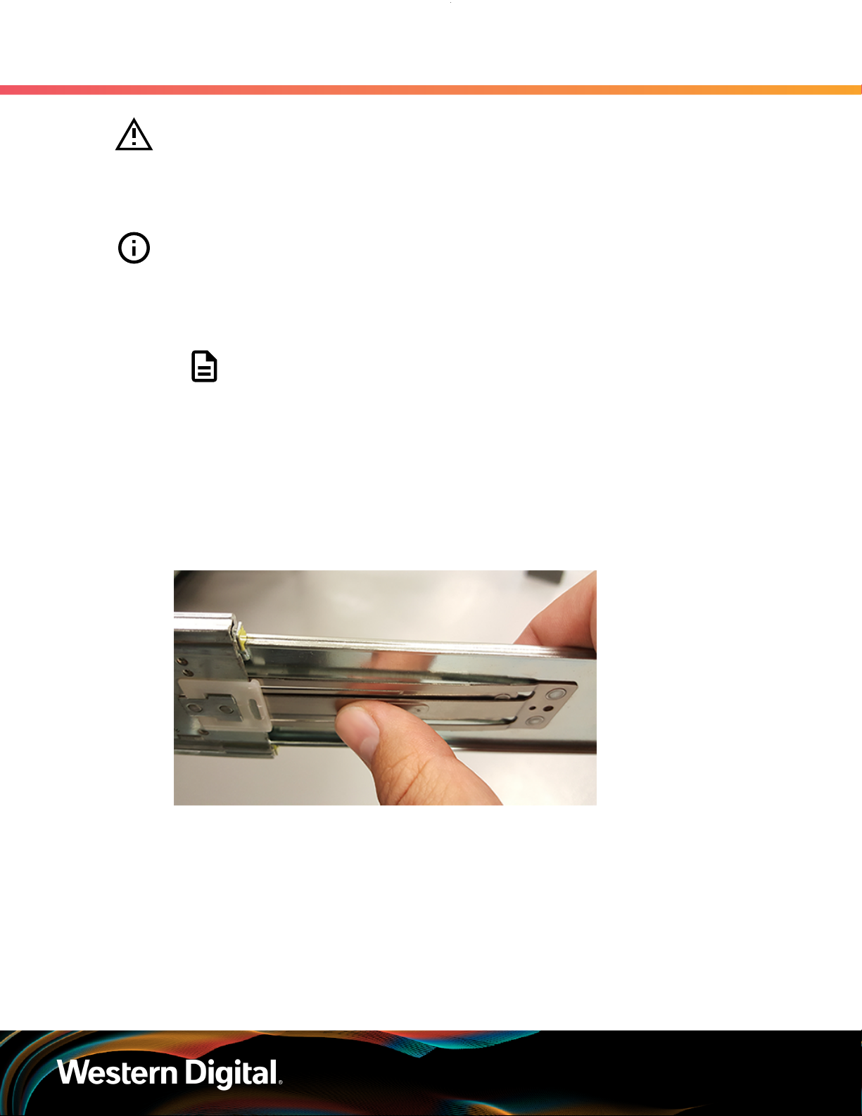
Step 1 : Remove the inner rail that is nested inside the rack rails.
5. Installation
5.2 Ultrastar Data60 Installation Procedure
Note: There are Right and Left rails and they must be installed as a set. Each inner
rail will read "R" for the right or "L" for the left embossed on the inside. Each outer
rail will read "R-Front" for the right or "L-Front" for the left. Right and Left refer to
when you are facing the front of the rack.
a. Start by sliding the inner rail out of the outer/rack rail until the safety latch engages and the
inner rail will not extend further. It will only slide one way.
b. Press on the safety latch release spring located on the side of the rail and slide the inner rail
out the rest of the way.
Figure 14: Rail Safety Latch
Step 2 : Install the inner rail onto the chassis making sure they are installed on the correct side. Each inner
rail will read "R" for the right or "L" for the left embossed on the side that faces away from the
chassis. Right and Left are with reference to looking at the front of the enclosure.
a. Orient the inner rails so that the flat side is facing the enclosure and the side with the
grooves is facing away from the enclosure.
Align the keyholes on the inner rail to the mounting pegs on the side of the enclosure and
b.
press the inner rail flush against the chassis. If the keyholes don't line up with the pegs, flip
the rail length-wise to see if this will align them.
36
Page 44

Installation Guide
c.
5. Installation
5.2 Ultrastar Data60 Installation Procedure
Figure 15: Inner Rail Attachment
Slide the inner rail toward the rear of the chassis to lock it in place. There will be an audible
click and the mounting pegs will cover the front part of the keyhole.
Figure 16: Slide Inner Rail
d.
Install the two special low-profile M4 x 3.2mm Philips screws provided to secure the inner rail
to the chassis.
e. Follow these steps for the second inner rail on the opposite side of the enclosure.
Step 3 : Secure the Cable Tray onto the enclosure using the included M3 x 8mm T10 Torx screws and the
Long T10 Torx Screwdriver. These screws should be tightened to .33-.56 Nm / 3-5 in-lbf using a
Long T10 Torx Screwdriver.
Caution: When installing the inner rail onto the chassis, make sure to only use
the special Low-Profile M4 x 3.2mm Philips screws provided in the accessory
kit with the CMA. These screws should be tightened to .90-1.12 Nm / 8-10 inlbf using a # 2 Philips Screwdriver. These screws are specially designed for this
purpose. Using unapproved screws could cause damage to the slides inside
the rail.
37
Page 45

Installation Guide
Figure 17: Installing the Cable Tray
5. Installation
5.2 Ultrastar Data60 Installation Procedure
Step 4 :
Step 5 : Install the outer rails into the rack. Pay special attention to which side is being installed. The
Set the vertical rack rail depth to 24" and 32".
embossed R is for the right side and L is for the left side. Right and Left refer to when you are
facing the front of the rack.
a. Move to the rear of the rack.
Orient the rail so that the word "REAR" that is embossed into the metal of the rail is at the
b.
rear end of the rack, and the release latch is facing the inside of the rack posts as shown in
the following image.
Figure 18: Rear Rail Latch Release Latch
c. Align the rail on the rack posts at the U-height desired for installation. The bottom of the rail
will be the lower most U of the total 4U height.
d. Pull the rail toward the rack post until the toolless latching mechanism engages the rack. The
latching mechanism may need to be pulled open to get around the rack post.
e. Move to the front of the rack.
38
Page 46

Installation Guide
f. Align the front of the rail with the holes on the rack posts that will receive the rails and pull
5. Installation
5.2 Ultrastar Data60 Installation Procedure
the rail toward the holes until the toolless latching mechanism engages the rack.
Figure 19: Front Rail Release Clip Operation
g. Use a level to make sure that the rails are aligned properly.
h. Follow these steps for the other outer rail.
Step 6 : Install the rail mounting hardware, starting with the uppermost rack mounting hole of the 4U
space on the front of the rack.
a. Install one cagenut at the uppermost mounting hole of the 4U space that the enclosure will
occupy.
If the Ultrastar Data60 will be installed in a rack for shipping purposes, install four more M5
b.
cage nuts in the holes 3-6 of the 4U space. These will receive the M5 x 12mm T15 Flat Head
Torx screws that secure the enclosure to the rack with the shipping bracket.
39
Page 47

Installation Guide
5. Installation
5.2 Ultrastar Data60 Installation Procedure
Figure 20: Cage Nut Spacing
Step 7 : Install the rear cover alignment brackets.
a. From the rear of the rack, orient the alignment brackets so that the groove that will catch the
cover is facing the inside of the rack.
40
Page 48

Installation Guide
5. Installation
5.2 Ultrastar Data60 Installation Procedure
Figure 21: Alignment Bracket Groove (highlighted in red)
Use five of the M5 x 12mm T15 Flat Head Torx screws and five of the included washers
b.
and attach the rear cover alignment bracket to the vertical rail with the Long T15 Torx
Screwdriver. Add three M5 x 12mm T15 Flat Head Torx screws and three included washers
to attach the rear rail (the three lower holes) to the rack posts as shown in the following
image. These screws should be tightened to 3.38-3.61 Nm / 30-32 in-lbf using a Long T15
Torx Screwdriver.
Figure 22: Screw and Washer Order
Caution: Be careful to set the screws properly cover alignment bracket and
rail to prevent crossthreading.
41
Page 49

Installation Guide
5. Installation
5.2 Ultrastar Data60 Installation Procedure
Figure 23: Screw Installation Location
Step 8 : Install the two rack latch brackets at the front of the rack.
a. Orient the brackets so that the screw holes are between the two pins supporting the outer
rails as shown in the following image. There is a left and a right. Use the image below as a
guide for how to orient this bracket and mirror it for the other side. Notice the increased
distance between the top two screw holes and the lower screwholes and the flange being
oriented on the outside.
42
Page 50

Installation Guide
5. Installation
5.2 Ultrastar Data60 Installation Procedure
Figure 24: Rack Latch Bracket Installed
b. Use 6 of the included M5 x 12mm screws and the T15 Torx screwdriver to install each bracket,
3 screws per bracket.
Caution: Always install the top cover onto the enclosure before installing the chassis into a
rack. Not having the top cover installed may damage the alignment brackets.
Step 9 : Extend the mid-rails out of the rack so that they are protruding from the front of the rack and the
safety latches engage.
43
Page 51

Installation Guide
Figure 25: Extend Mid-Rails
5. Installation
5.2 Ultrastar Data60 Installation Procedure
Step 10 : Install the chassis into the rails.
a. Extend the bearing plates on the inside of the mid-rails until they are fully forward (detent
has engaged). This prevents potential damage due to improper mating of the rails.
Figure 26: Bearing Plate
44
Page 52

Installation Guide
b. Caution: This step in the installation requires a minimum of 3 individuals to
5. Installation
5.2 Ultrastar Data60 Installation Procedure
install safely, two to lift and one to guide the others who may have difficulty
seeing because the enclosure is in the way. Ensure that the appropriate
measures are taken to safely support the enclosure during installation. The
enclosure MUST have no drives installed and requires a two person team lift to
install. Do not attempt to lift the system if it is fully populated with drives.
The only case in which the system may be installed or removed with the drives
populated is if the facility has a lift that is rated to handle the maximum weight
of the fully loaded system.
Warning: The handles on the front of the chassis are not intended to be used
to support the weight of the Ultrastar Data60 . Lifting the unit by the chassis
handles or trying to support the unit on the handles can cause them to fail. This
can cause serious damage to the unit or serious bodily harm to those handling
the unit. Always team lift the chassis by gripping the underside of the unit, and
never try to lift a chassis that is filled with drives.
Warning: Do not lift the chassis by the Cable Tray while removing the chassis
from the rack OR while installing it into a rack. This can cause serious damage
to the unit or serious bodily harm to those handling the unit. Always team lift
the chassis by gripping the underside of the unit, and never try to lift a chassis
that is filled with drives.
In preparation to perform a team lift, position one individual on each side of the enclosure
(to lift) and a third individual standing at the protruding rack rails (to guide the chassis to
mate with rack rails).
c.
Team-lift the enclosure until the inner rails (which are attached to the chassis) align with the
extended mid-rails (which are attached to the rack), and guide the inner rails on the chassis
to mate with the rack rails.
45
Page 53

Installation Guide
5. Installation
5.2 Ultrastar Data60 Installation Procedure
Figure 27: Installing the Chassis
d.
Once the rails are mated properly, slide the enclosure into the rack until it is stopped by the
safety catch on the rails. Push the release lever on the safety latch (located on the side of
each of the rails), and push the enclosure the rest of the way into the rack.
Figure 28: Safety Latch Release
e. As the chassis is slid into the rack, position one installer at the rear of the rack to ensure that
the pegs on the sides of the cover will slide correctly into the rear cover alignment brackets
on both sides of the rack. If the chassis does not install smoothly or snags, check that the
rear cover alignment brackets are not interfering with the chassis sidewalls, and try again.
Step 11 : Install the crossbar onto the CMA mounting bracket.
a. Align the crossbar with the mounting peg facing down and pointing toward the CMA
mounting bracket.
46
Page 54

Installation Guide
b.
5. Installation
5.2 Ultrastar Data60 Installation Procedure
Figure 29: Initial Alignment
Insert the peg on the underside of the crossbar into the slot on the CMA mounting bracket.
Figure 30: Crossbar Underside Peg
c. Swing the crossbar so that the thumbscrew lines up with the mounting hole on the opposite
side of the enclosure.
47
Page 55

Installation Guide
5. Installation
5.2 Ultrastar Data60 Installation Procedure
Figure 31: Swinging Motion of Crossbar to Locking Position
d. Press the crossbar against the CMA mounting bracket and secure the crossbar in place by
pressing and turning the thumbscrew clockwise until snug.
Figure 32: Tightening the Thumbscrew
a. Check that the crossbar is fully secured to the CMA mounting bracket by pulling on the bar
to ensure it does not move.
Step 12 : Install the CMA(s).
Note: The CMA has two arms, labeled "upper" and "lower." The lower arm should
have the elbow on the left side and be installed first; the upper arm should have
the elbow on the right side and be installed last.
48
Page 56

Installation Guide
a. Orient the CMA so that the elbow is on the left hand side.
b. Attach all three of the connectors to the brackets on the rails. There should be one at the
5. Installation
5.2 Ultrastar Data60 Installation Procedure
elbow side and two at the other end.
Figure 33: Lower CMA Orientation
c. Slowly slide the enclosure forward to ensure the arm is operating properly, then slide it back
into the rack.
a. Repeat these steps to install the upper arm with the elbow facing to the right.
Step 13 : Cable the CMA(s).
a. Unlatch the elbow side of the arm(s) by pressing the blue button labeled “push,” and then
swing the arm(s) open.
Gather the SAS, power, and Ethernet cables for installation. Before cabling, note the
b.
following routing patterns for best results:
Note: Route the cables supported by the lower arm to IOM A (left hand side
looking at the rear). Second, route the cables supported by the upper arm to
IOM B (right hand side looking at the rear) in a "criss-cross" pattern. See the
Special Considerations for Cable Routing (page 60) for more information.
49
Page 57

Installation Guide
5. Installation
5.2 Ultrastar Data60 Installation Procedure
Figure 34: CMA Cable Routing
c.
Open all of the baskets.
Figure 35: Open Baskets
50
Page 58

Installation Guide
d. Connect the Ethernet cable to the Ethernet port, and route the cable through each of the
e. Connect the SAS cables to the SAS ports, and route them through the baskets one at a time.
f.
g.
5. Installation
5.2 Ultrastar Data60 Installation Procedure
baskets on the arm.
Make sure to follow the labels to ensure they are connected to the proper ports.
Connect the power cable to the PSU and route it through each basket.
Attention: Make sure the power cable is not connected to a PDU. If it is,
the system will power up when the cable is connected to a PSU. This is not
intended at this stage of installation.
If the installation includes more than 10 total cables, follow the recommendations in Special
Considerations for Cable Routing (page 60), before proceeding.
Note: Each cable must be given enough slack at the connector end to operate
smoothly. Allow 20 - 21 in. (508 – 533.4 mm) between the connector and the
first basket.
Figure 36: Nominal Cable Length at Connectors
h. Close all of the baskets.
i. If the Ultrastar Data60 is being installed in a rack and will subsequently be transported
inside that rack, it is important to use the included cable tie to wrap the CMA bundle to
ensure it does not get damaged during transport. If the Ultrastar Data60 is instead being
installed where it will be operated, skip this step. Remember to remove the cable ties after
the enclosure has reached its final operational location.
j. Reconnect the arm at the elbow to the connectors on the rail.
51
Page 59

Installation Guide
Step 14 : Make sure the CMA(s) is in operational position by folding the arm(s) in toward the enclosure and
attaching the elbow end(s) to the connector(s) attached to the rail. Verify that all of the cabling is
in functional order and does not bind or catch.
Step 15 :
Step 16 : Secure the chassis top cover to the rack using the captive M5 thumb-screws as shown in the
Test for binding in the extension of the arm by gently pulling the enclosure out of the rack,
ensuring the cables extend properly and that the system doesn’t bind at all. If it does, examine
the point at which the binding occurred and adjust the seating of cables in the baskets, check
the connections to the rails, and examine the joints of the arm to ensure that they are all
functioning properly.
following image. Use a T15 Torx screwdriver, and tighten the screws to 3.38-3.61 Nm / 30-32 inlbf.
Figure 37: Cover Retention Screws
5. Installation
5.2 Ultrastar Data60 Installation Procedure
Step 17 : Now that the chassis is installed, test the installation by sliding the enclosure in and out of the
rack a minimum of three times. If the enclosure binds, catches, or displays any incorrect motion
or behavior repeat the installation.
Note: Adjustments of the vertical rack rails may be required to fix any issues that
may occur.
Step 18 : Grasp both handles at the front of the enclosure and pull with even pressure to extend the
chassis out of the rack until it is stopped by the safety latches. The safety latches will prevent the
enclosure from coming out of the rack completely and the cover will remain in the rack attached
to the rear alignment brackets.
52
Page 60

Installation Guide
Figure 38: Chassis Handle Operation
5. Installation
5.2 Ultrastar Data60 Installation Procedure
Step 19 :
Step 20 : Install the 3.5in HDD Assembly.
Perform this same action two more times without the drives loaded to make sure the rail kits are
installed properly.
Note: The 2.5in SSD Assembly is installed in the same manner as the 3.5in HDD
Assembly. For instructions on assembling the 2.5in SSD Assembly, see Operating
the 2.5" Drive Carrier (page 56).
a. Ensure that the enclosure has been pulled out of the rack until the rail latches engage.
Find the LED pointer on the top of the drive carrier. This pointer should point toward the
b.
front of the unit as shown in the following image.
53
Page 61

Installation Guide
5. Installation
5.2 Ultrastar Data60 Installation Procedure
Figure 39: LED Pointer Orientation
c. Align the drive with the empty slot that will receive it. Lower it into the slot, making sure it
stays level and does not snag.
54
Page 62

Installation Guide
5. Installation
5.2 Ultrastar Data60 Installation Procedure
Figure 40: Installing a 3.5in HDD Assembly
d. Pinch the latch release and carefully press downward to seat the 3.5in HDD Assembly the
rest of the way.
Step 21 : Repeat the preceding steps to install each subsequent HDD using the same method as the first,
populating the enclosure from left-to-right, rear-to-front.
For example, begin with slot 48 (as shown in the following diagram), continue through 59, then
proceed with 36 through 47, and so on:
Figure 41: Drive Layout
55
Page 63

Installation Guide
5. Installation
5.2 Ultrastar Data60 Installation Procedure
Caution: To ensure proper airflow for enclosure cooling, all drive slots must be
populated with either drives or drive blanks.
Step 22 :
Step 23 : If the chassis is being installed into a rack that will be shipped fully assembled, you must install
Now that the drives are installed into the chassis, test the installation by sliding the enclosure
in and out of the rack a minimum of three times. If the enclosure binds, catches, or displays any
incorrect motion or behavior retry the installation of the drives and chassis.
eight (four per side) of the included M5 x 12mm T15 Flat Head Torx screws into the two brackets
at the front of the chassis in the following locations. These screws should be tightened to
3.38-3.61 Nm / 30-32 in-lbf using a Long T15 Torx Screwdriver. If this chassis will not be installed
into a rack for shipping purposes, skip this step and move on to the next one.
Figure 42: Shipping Bracket Screw Locations
Step 24 : Plug the enclosure power cords into a PDU to power the enclosure.
Caution: The Ultrastar Data60 can only be plugged into high line (200 - 240 VAC)
power. If the unit is plugged into low line (110-127 VAC), the PSU will report a
"Critical" state when status pages are queried using SES. In this case, the enclosure
will power up, but the drives will not. The enclosure will remain in low-power
mode.
Step 25 :
Result: The enclosure is now installed.
What to do next: For instructions on how to operate the enclosure, please refer to the Ultrastar Data60
User Guide.
Double check the power indicators and other LEDs to ensure that the system is booting.
5.2.1 Operating the 2.5" Drive Carrier
Follow these steps to operate the clamping mechanism and install a 2.5" drive in the carrier.
Step 1 : Locate the release clips on the rear and press them inward to release the clamp.
56
Page 64

Installation Guide
Figure 43: Clamp Release (clamp shown in blue for visual clarity)
Step 2 : Slide the clamp in the direction shown in the following image to loosen it from the drive. Be
sure not to slide too far as this will allow the clamp to fall from the carrier body and it will have
to be reinstalled.
5. Installation
5.2 Ultrastar Data60 Installation Procedure
Figure 44: Clamp Slide (clamp shown in blue for visual clarity)
Step 3 :
Step 4 : Slide the clamp back toward the drive making sure that the two plastic pins on the side of the
Insert the 2.5" drive into the drive slot so that it is snug into the corner.
drive properly install into the drive screwholes. If these pins are not seated properly, unlatch the
clamp and retry.
57
Page 65

Installation Guide
Figure 45: Clamp Pins (clamp shown in blue for visual clarity)
5. Installation
5.3 SAS Cabling
5.3 SAS Cabling
The Ultrastar Data60 can use passive cables up to 3m in length, or active cables up to 10m, for SAS
connections to the host. Active cables must be used for Ultrastar Data60 to Ultrastar Data60 daisy-chaining
connections. All approved passive and active SAS cables are listed in the following table.
Note: MegaRAID adapters do not support the use of active SAS cables. If your configuration
requires the use of MegaRAID adapters, passive cables must be used.
Table 27: Approved SAS Cables
Type Length Manufacturer Vendor Part Number
Active Optical
HD Mini-SAS to HD Mini-SAS
4. Listed FOHHB23P00xxx cables are compatible, beginning with FW 2052-003.
3. Active cables can be used for both direct (host-to-enclosure) and daisy-chain (enclosure-to-enclosure) connections.
3
3m
4m Amphenol ICC (FCI) FOHHB23P00004
Amphenol ICC (FCI) FOHHB23P00003
Molex 106415-2103
4
58
Page 66

Installation Guide
5. Installation
5.3 SAS Cabling
Type Length Manufacturer Vendor Part Number
Amphenol ICC (FCI) FOHHB23P000055m
Molex 106415-2105
6m Amphenol ICC (FCI) FOHHB23P00006
10m Molex 106415-2110
Passive
HD Mini-SAS to HD Mini-SAS
Active Cables
When daisy-chaining multiple Ultrastar Data60 enclosures together, active cables must be used between
enclosures for improved signal integrity.
Passive Cabling
As a best practice, Western Digital requires connecting the cables to every other SAS connector port when
connecting more than one host per IOM. Please refer to Table 28: Recommended IOM Port Connection
Order (page 59) for port connection ordering required for IOMA and IOMB:
5
1m Amphenol ICC (FCI) 10112041-2010LF
2m
3m
Amphenol ICC (FCI) 601760006
CS Electronics 12G-HD-4444/2M
Data Storage Cables (DSC) C5555-2M
The Mate Company (TMC) C5555-2M
10112041-2020LFAmphenol ICC (FCI)
10117949-2020LF
Molex 1110751002
Amphenol ICC (FCI) 601760008
CS Electronics 12G-HD-4444/3M
10112041-2030LFAmphenol ICC (FCI)
10117949-4030LF
Molex 1110751003
5. Passive cables should only be used for direct (host-to-enclosure) connections.
59
Page 67

Installation Guide
5.4 Special Considerations for Cable Routing
Table 28: Recommended IOM Port Connection Order
IOM 1st Host 2nd Host 3rd Host 4th Host 5th Host 6th Host
A A6 A4 A2 A5 A3 A1
B B1 B3 B5 B2 B4 B6
Edge Buffering
Edge buffering is an enclosure feature that increases the overall performance when a 6Gb/s target is
connected. With edge buffering disabled, primitives that can be deleted from the initiator are added to
slow the effective logical rate to the slowest target device connected between the initiator and the target
device. With edge buffering enabled, the expanders buffer data from slower 6Gb/s targets to utilize the
12Gb/s link from the expander to the initiator in a more efficient manner.
5.4 Special Considerations for Cable Routing
There are a number of special considerations installers should take when routing cables through the CMA.
This section outlines those considerations.
The distance from the end of the connector at the port to the first basket on the CMA should be 20” – 21”
long. This will give the cables enough slack at this end to prevent stress on the port and binding during
operation cycles.
5. Installation
Figure 46: Nominal Cable Length at Connectors
60
Page 68

Installation Guide
The cables at the port side of the CMA should crisscross in front of the IOMs. To accomplish this, the cables
connected to the ports for IOM B (right hand side when facing the rear) should be connected to the upper
CMA, and the cables connected to the ports for IOM A (left hand side when facing the rear) should be
connected to the lower CMA.
Figure 47: Crisscross Cables
5. Installation
5.4 Special Considerations for Cable Routing
When the cables are routed into the CMA, make sure there is some slack given to the elbow joint of the
CMA. It is recommended not to wrap the cables tightly around this joint because this can cause binding and
prevent smooth operation. To ensure there is enough slack at the elbow, pull the enclosure in and out of the
rack and have another installer check for binding in the elbow joint. Make sure the cables are bending and
not twisting.
Figure 48: CMA Elbow with Full Cable Bundle
61
Page 69

Installation Guide
At the end of the CMA where the cables exit, use a cable tie to bundle the cables together. Make sure the
cables are bending and not twisting.
Figure 49: Cable Tie at Exit of CMA
5. Installation
5.5 Cabling for CMA
5.5 Cabling for CMA
5.5.1 Before You Begin
The cable configurations detailed in this section are intended to provide the optimal setup for your specific
configuration. During the cabling of the CMA, the HD Mini-SAS and SFP+ cables should be installed into the
CMA first, followed by Ethernet cables, and finally the power cables on top.
How to Use the Service Loop Dimension Figure and Table
This section uses the concept of service loops to inform the user on how to prepare HD mini-SAS cables
for installation into the CMA. The power and Ethernet cables do not need to be added to the Service
Loop bundle. This concept utilizes measurements that begin at the connector end of the cable and along
the cable itself. The Service Loop Dimensions figure and the Service Loop Dimensions table are paired
together to communicate the length in which connectors, velcro, and the CMA cage must be set at to
avoid binding or snagging.
Note: The measurement provided in this section are only suggested values based on product
testing. Your specific situation may vary. Adjust the measurement as necessary to avoid cable
binding or sagging below the rear of the enclosure.
1. Identify the configuration that is needed for the particular setup and locate the Service Loop
Dimension table related to that configuration.
2. Take the first measurement (letter A) and measure that length from the connector on the cable to the
edge of where the first verco strip will go. Apply the velco strip.
3. Repeat this action for the B and C values until the table has been completed.
Here is an example of the Service Loop Dimension Figure and Table:
62
Page 70

Installation Guide
Figure 50: Service Loop Dimension Figure
Table 29: Example Service Loop Dimension Table
In this case, the first measurement from the tip of the cable to the first velco strip is 6in. Followed by a 12in.
measurement to the CMA cage. There is no need for a B value due how short this configuration is.
5. Installation
5.5 Cabling for CMA
A B C
6in. N/A 12in.
5.5.2 Cabling CMA
5.5.2.1 SFP+ and HD Mini-SAS Cable Configuration
This configuration includes the use of up to four SFP+ and two HD Mini-SAS cables installed into a CMA
arm.
Figure 51: Service Loop Dimension Figure
Table 30: Service Loop Dimension Table
A B C
6in. 12in. 16in.
63
 Loading...