

Page 1

User Guide
OpenFlex™ F3x00 and E3000
1ET2212
Version 1.1
December 2020
Page 2

User Guide Table of Contents
Table of Contents
Revision History.................................................................................................................................... iv
Notices....................................................................................................................................................v
Points of Contact.................................................................................................................................. vi
Chapter 1. Overview.........................................................................................................1
OpenFlex F3x00 and E3000................................................................................................................ 2
Servicing Features.........................................................................................................................3
Composable Infrastructures......................................................................................................... 3
NVMe-oF........................................................................................................................................ 4
Supported SKUs............................................................................................................................4
System Architecture Overview........................................................................................................... 5
System High Speed Data Ingest Architecture........................................................................... 5
System Thermal and Cooling...................................................................................................... 5
Electrical Specifications....................................................................................................................... 7
Environmental Specifications.............................................................................................................. 8
Mechanical Specifications................................................................................................................... 8
Performance Specifications................................................................................................................. 9
Physical Design.................................................................................................................................... 11
LEDs.............................................................................................................................................. 13
Cables...........................................................................................................................................16
Restrictions and Limitations............................................................................................................... 16
Site Requirements............................................................................................................................... 17
Power Requirements................................................................................................................... 17
Rack Requirements...................................................................................................................... 17
Thermal and Cooling Requirements..........................................................................................18
Installation and Servicing Requirements................................................................................... 18
Chapter 2. Components............................................................................................... 20
Chassis................................................................................................................................................. 21
i
Page 3

User Guide Table of Contents
Chassis Specifications................................................................................................................. 21
PSU...................................................................................................................................................... 22
PSU Specifications...................................................................................................................... 22
Fan Module......................................................................................................................................... 23
Fan Module Specifications......................................................................................................... 23
BMC Module....................................................................................................................................... 24
BMC Module Specifications....................................................................................................... 24
Rails......................................................................................................................................................25
Rails Specifications..................................................................................................................... 25
OpenFlexF3x00................................................................................................................................... 26
OpenFlexF3x00 Specifications...................................................................................................26
OpenFlex E3000 Fabric Device Blank...............................................................................................27
E3000 Fabric Device Blank Specifications...............................................................................27
List of Field/Customer Replaceable Units....................................................................................... 28
Chapter 3. Management............................................................................................... 29
OCGUI................................................................................................................................................. 30
Compatible Browsers.................................................................................................................30
Login Page.................................................................................................................................. 30
Dashboard.................................................................................................................................... 31
Storage Device Page..................................................................................................................36
Chassis Device Page.................................................................................................................. 43
Basic Operational Functions...................................................................................................... 50
Maintenance................................................................................................................................ 96
Firmware Upgrade.................................................................................................................... 106
Part Replacement.............................................................................................................................. 113
Fan Module Replacement..........................................................................................................113
PSU Replacement.......................................................................................................................116
BMC Module Replacement.......................................................................................................120
ii
Page 4

User Guide Table of Contents
OpenFlexF3x00 Replacement...................................................................................................123
Rails Replacement..................................................................................................................... 127
Chassis Replacement................................................................................................................ 145
Chapter 4. Safety......................................................................................................... 166
Electrostatic Discharge.....................................................................................................................167
Optimizing Location..........................................................................................................................167
Power Connections...........................................................................................................................167
Power Cords......................................................................................................................................167
Rackmountable Systems.................................................................................................................. 168
Restricted Access Location............................................................................................................. 168
Safety and Service............................................................................................................................ 168
Safety Warnings and Cautions........................................................................................................ 169
Chapter 5. Regulatory................................................................................................. 170
Europe (CE Declaration of Conformity)........................................................................................... 171
FCC Class A Notice...........................................................................................................................171
ICES-003 Class A Notice—Avis NMB-003, Classe A....................................................................... 171
Japanese Compliance Statement, Class A ITE................................................................................171
KCC Notice (Republic of Korea Only), Class A ITE........................................................................ 172
Taiwan Warning Label Statement, Class A ITE...............................................................................172
iii
Page 5

User Guide Revision History
Revision History
Date Revision Comment
July 2020 1.0 Initial Release
December 2020 1.1 Added UK Import Representation Contact
iv
Page 6

User Guide Notices
Notices
Western Digital Technologies, Inc. or its affiliates' (collectively “Western Digital”) general policy does not
recommend the use of its products in life support applications wherein a failure or malfunction of the product
may directly threaten life or injury. Per Western Digital Terms and Conditions of Sale, the user of Western
Digital products in life support applications assumes all risk of such use and indemnifies Western Digital
against all damages.
This document is for information use only and is subject to change without prior notice. Western Digital
assumes no responsibility for any errors that may appear in this document, nor for incidental or consequential
damages resulting from the furnishing, performance or use of this material.
Absent a written agreement signed by Western Digital or its authorized representative to the contrary,
Western Digital explicitly disclaims any express and implied warranties and indemnities of any kind that may,
or could, be associated with this document and related material, and any user of this document or related
material agrees to such disclaimer as a precondition to receipt and usage hereof.
Each user of this document or any product referred to herein expressly waives all guaranties and warranties
of any kind associated with this document any related materials or such product, whether expressed or
implied, including without limitation, any implied warranty of merchantability or fitness for a particular
purpose or non-infringement. Each user of this document or any product referred to herein also expressly
agrees Western Digital shall not be liable for any incidental, punitive, indirect, special, or consequential
damages, including without limitation physical injury or death, property damage, lost data, loss of profits or
costs of procurement of substitute goods, technology, or services, arising out of or related to this document,
any related materials or any product referred to herein, regardless of whether such damages are based on
tort, warranty, contract, or any other legal theory, even if advised of the possibility of such damages.
This document and its contents, including diagrams, schematics, methodology, work product, and
intellectual property rights described in, associated with, or implied by this document, are the sole and
exclusive property of Western Digital. No intellectual property license, express or implied, is granted by
Western Digital associated with the document recipient's receipt, access and/or use of this document or the
products referred to herein; Western Digital retains all rights hereto.
Western Digital, the Western Digital logo, and OpenFlex are registered trademarks or trademarks of Western
Digital Corporation or its affiliates in the US and/or other countries. All other marks are the property of their
respective owners. Product specifications subject to change without notice. Pictures shown may vary from
actual products. Not all products are available in all regions of the world.
Western Digital
5601 Great Oaks Parkway
San Jose, CA 95119
© 2020 Western Digital Corporation or its affiliates. All Rights Reserved.
v
Page 7

User Guide Points of Contact
Points of Contact
For further assistance with a Western Digital product, contact Western Digital Datacenter Platforms technical
support. Please be prepared to provide the following information: part number (P/N), serial number (S/N),
product name and/or model number, and a brief description of the issue.
Email:
support@wdc.com
Website:
https://portal.wdc.com/Support/s/
UK Import Representation Contact
Western Digital UK Limited Hamilton House, Regent Park, Kingston Road Leatherhead, Surrey KT22 7PL, GB,
United Kingdom
Telephone: +44 1372 366000
vi
Page 8

Western Digital
Overview
In This Chapter:
- OpenFlex F3x00 and E3000..........................2
- System Architecture Overview.....................5
- Electrical Specifications.................................7
- Environmental Specifications........................8
- Mechanical Specifications............................. 8
- Performance Specifications...........................9
- Physical Design.............................................. 11
- Restrictions and Limitations........................ 16
- Site Requirements.........................................17
1
Page 9
User Guide
1.1 OpenFlex F3x00 and E3000
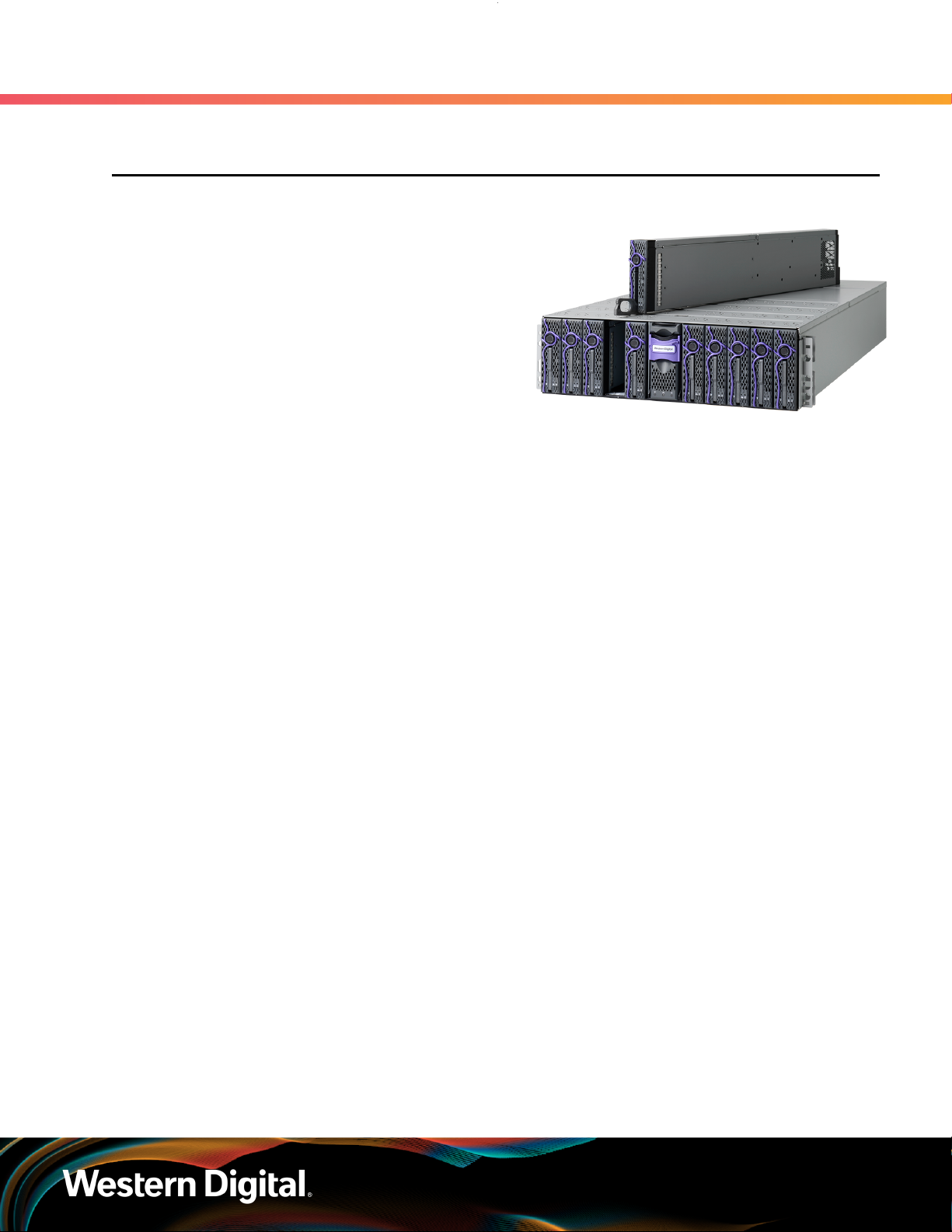
The OpenFlex F3x00 and E3000 is a 3U rack
mounted data storage enclosure built on the
OpenFlex platform. OpenFlex is Western Digital’s
architecture that supports Open Composable
Infrastructure (OCI). The OpenFlex F3x00 and E3000
are fabric devices that leverage this OCI approach
in the form of disagreggated data storage using
NVMe-over-Fabrics (NVMe-oF™). NVMe-oF is a
networked storage protocol that allows storage
to be disaggregated from compute to make that
storage widely available to multiple applications and
servers. By enabling applications to share a common
pool of storage capacity, data can be easily shared
between applications, or needed capacity can be
allocated to an application regardless of location. Exploiting NVMe™ device-level performance, NVMeoF promises to deliver the lowest end-to-end latency from application to shared storage. NVMe-oF
enables composable infrastructures to deliver the data locality benefits of NVMe DAS (low latency, high
performance) while providing the agility and flexibility of sharing storage and compute.
The maximum data storage capacity is 614TB1 when leveraging a full set of 10 F3x00 fabric devices.
The enclosure runs on an input voltage of 200V - 240V and consumes ~1400W of power under typical
conditions. It requires a maximum of 1600W at full load.
1. Overview
1.1 OpenFlex F3x00 and E3000
Composable Infrastructure
An emerging category of
datacenter infrastructure that
seeks to disaggregate compute,
storage, and networking fabric
resources into shared resource
pools that can be available
for on-demand allocation (i.e.,
“composable”). Composability
occurs at the software level,
disaggregation occurs at the
hardware level using NVMe™over-Fabric—will vastly improve
compute and storage utilization,
performance, and agility in the
data center.
• 614TB
• 12GBps NVMe-oF over QSFP28
• 68.5 kg (151.1 lbs.)
2
Cables
OpenFlex
OpenFlex is Western Digital’s
architecture that supports Open
Composable Infrastructure
through storage disaggregation
– both disk and flash natively
attached to a scalable fabric.
OpenFlex does not rule out
multiple fabrics, but whenever
possible, Ethernet will be used as
a unifying connect for both flash
and disk because of its broad
applicability and availability.
• 200V - 240V Input Voltages
• 3U Form Factor
• Hot-swappable PSUs and Fans
Open Composable API
Western Digital's new Open
Composable API is designed
for data center composability.
It builds upon existing industry
standards utilizing the best
features of those standards as
well as practices from proprietary
management protocols.
• Dual 1600W PSUs
• Operational Temperature: 5°C to
35°C
• Dynamic Provisioning Supported
1. Max storage capacity depends on device version and device configuration.
2
Page 10

User Guide
1.1.1 Servicing Features
The OpenFlex F3x00 and E3000 are equipped with several features that make servicing simpler and safer.
• Every CRU component has been designed with toolless removal features.
• The BMC Module, Fan Module, PSU, and F3x00 devices are all hotswappable components.
This document provides full instructions on how these features operate in the Management (page 29)
section.
1.1.2 Composable Infrastructures
An emerging category of datacenter infrastructure that seeks to disaggregate compute, storage, and
networking fabric resources into shared resource pools that can be available for on-demand allocation (i.e.,
“composable”). Composable occurs at the software level, disaggregation occurs at the hardware level.
Western Digital’s vision for Open Composable Infrastructures is based on four key pillars:
• Open
1. Overview
1.1 OpenFlex F3x00 and E3000
◦ Open in both API and form factor
◦ Designed for robust interoperability of multi-vendor solutions
• Scalable
◦ Ability to compose solutions at the width of the network
◦ Enable self-organizing systems of composable elements that communicate horizontally
• Disaggregated
◦ Pools of resources available for any use case that is defined at run time
◦ Independent scaling of compute & storage elements to maximize efficiency & agility
Extensible
•
◦ Inclusive of both disk and flash
◦ Entire ecosystem of composable elements managed & orchestrated using a common API
framework
◦ Prepared for yet-to-come composable elements – e.g., memory, accelerators
1.1.2.1 Open Composable
The Western Digital Open Composable Infrastructure (OCI) uses a common API to manage and
coordinate with all fabric-attached storage including pools of flash and disk. The infrastructure also
supports the management of networking and compute resources. The API is used for all managed
elements to accelerate the ability to use disaggregated resources where components are no longer subcomponents, but core elements connected to the network.
1.1.2.2 Open Composable API (OCAPI)
Western Digital’s Open Composable API is a RESTful interface for OpenFlex that enables a Unified Fabric
Control Plane for Storage Fabric Devices. This allows for composing disaggregated storage resources—
with compute, networking, and memory—into virtual systems in the future. These virtual systems will be
dynamically provided to the right application at the right time, ensuring SLAs can be met automatically.
3
Page 11

User Guide
• Volume management (create / modify / delete namespaces, format media)
• Monitor hardware sensors (temperatures, voltages, fan speeds, hardware state)
• Configure hardware (update firmware, reboot individual components or systems, assert LEDs)
• Monitor performance (statistics, bandwidth, IOPS, latency)
• Capture inventory data (serial number, part number, etc.)
• Capture log information
• Configure policies (user access lists, authentication, LUN masking, HTTPS/TLS encryption/security
• Self-discovery of other locally-available resources configurable using the Open Composable API for
1.1.2.3 OCGUI
The Open Composable Graphical User Interface (OCGUI) is the graphical representation of all of the data
shared up to the fabric by the OCAPI. This GUI is presented to the user by browsing to the IP address
of any device on the fabric. The GUI has a "command-center" design layout that presents all vital health,
utilization, and performance statistics related to devices on the network at a glance.
1. Overview
1.1 OpenFlex F3x00 and E3000
with certificate/key settings)
OpenFlex
1.1.3 NVMe-oF
Non-Volatile Memory Express over Fabric (NVMe-oF) is one of the primary enabling technologies for the
OpenFlex platform. NVMe-oF enables the high-speed, low-latency storage performance of NVMe over
a fabric switching network. OpenFlex products drive network communications across the fabric using
100Gb/s Ethernet protocol. This allows for a complex network of computing devices to all share the same
storage resources with very high performance.
1.1.4 Supported SKUs
The following table lists the versions of Western Digital product that are supported by this document.
Table 1: Devices
Device Volume Bandwidth3Drive Writes Encryption
OpenFlex F3000 Fabric Device 12.8TB 12GB/s RI-3DW/D ISE 1EX1906
OpenFlex F3000 Fabric Device 12.8TB 12GB/s RI-3DW/D SE 1EX1910
OpenFlex F3100 Fabric Device 12.8TB 12GB/s RI-2DW/D ISE 1EX2413
OpenFlex F3200 Fabric Device 12.8TB 12GB/s RI-2DW/D ISE 1EX2269
OpenFlex F3000 Fabric Device 15.2TB 12GB/s RI-1DW/D ISE 1EX1907
OpenFlex F3000 Fabric Device 15.2TB 12GB/s RI-1DW/D SE 1EX1911
Part
Number
OpenFlex F3100 Fabric Device 15.36TB 12GB/s RI-0.8DW/D ISE 1EX2416
OpenFlex F3200 Fabric Device 15.36TB 12GB/s RI-0.8DW/D ISE 1EX2272
OpenFlex F3000 Fabric Device 25.6TB 12GB/s RI-3DW/D ISE 1EX1908
OpenFlex F3000 Fabric Device 25.6TB 12GB/s RI-3DW/D SE 1EX1912
3. Bandwidth obtained by sequential read
4
Page 12
User Guide
1. Overview
1.2 System Architecture Overview
Device Volume Bandwidth3Drive Writes Encryption
OpenFlex F3100 Fabric Device 25.6TB 12GB/s RI-2DW/D ISE 1EX2414
OpenFlex F3200 Fabric Device 25.6TB 12GB/s RI-2DW/D ISE 1EX2270
OpenFlex F3000 Fabric Device 30.72TB 12GB/s RI-1DW/D ISE 1EX1909
OpenFlex F3000 Fabric Device 30.72TB 12GB/s RI-1DW/D SE 1EX1913
OpenFlex F3100 Fabric Device 30.72TB 12GB/s RI-0.8DW/D ISE 1EX2417
OpenFlex F3200 Fabric Device 30.72TB 12GB/s RI-0.8DW/D ISE 1EX2273
OpenFlex F3100 Fabric Device 51.2TB 12GB/s RI-2DW/D ISE 1EX2415
OpenFlex F3200 Fabric Device 51.2TB 12GB/s RI-2DW/D ISE 1EX2271
OpenFlex F3000 Fabric Device 61.44TB 12GB/s RI-1DW/D SE 1EX1914
OpenFlex F3100 Fabric Device 61.44TB 12GB/s RI-0.8DW/D ISE 1EX2418
OpenFlex F3200 Fabric Device 61.44TB 12GB/s RI-0.8DW/D ISE 1EX2274
1.2 System Architecture Overview
1.2.1 System High Speed Data Ingest Architecture
Part
Number
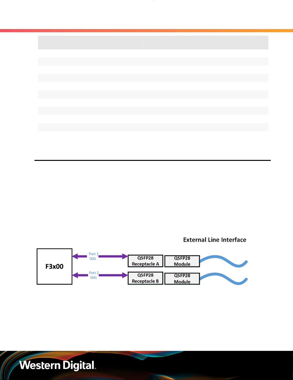
The system main data ingest architecture uses two separate 50G Ethernet connections each on a dual
QSFP28 connector on the rear I/O of the chassis. This completes the connection from the device that is
inserted into a chassis slot, through the backplane into the QSFP connectors. The architecture supports
the hot swap nature of the devices and does not require any sort of shut down or disconnection before
servicing. Each 100G Ethernet connection is split in half at the QSFP28 connectors resulting in 50G per
connector allowing for dual port functionality with the device.
Figure 2: System High Speed Data Ingest
1.2.2 System Thermal and Cooling
3. Bandwidth obtained by sequential read
5
Page 13
User Guide
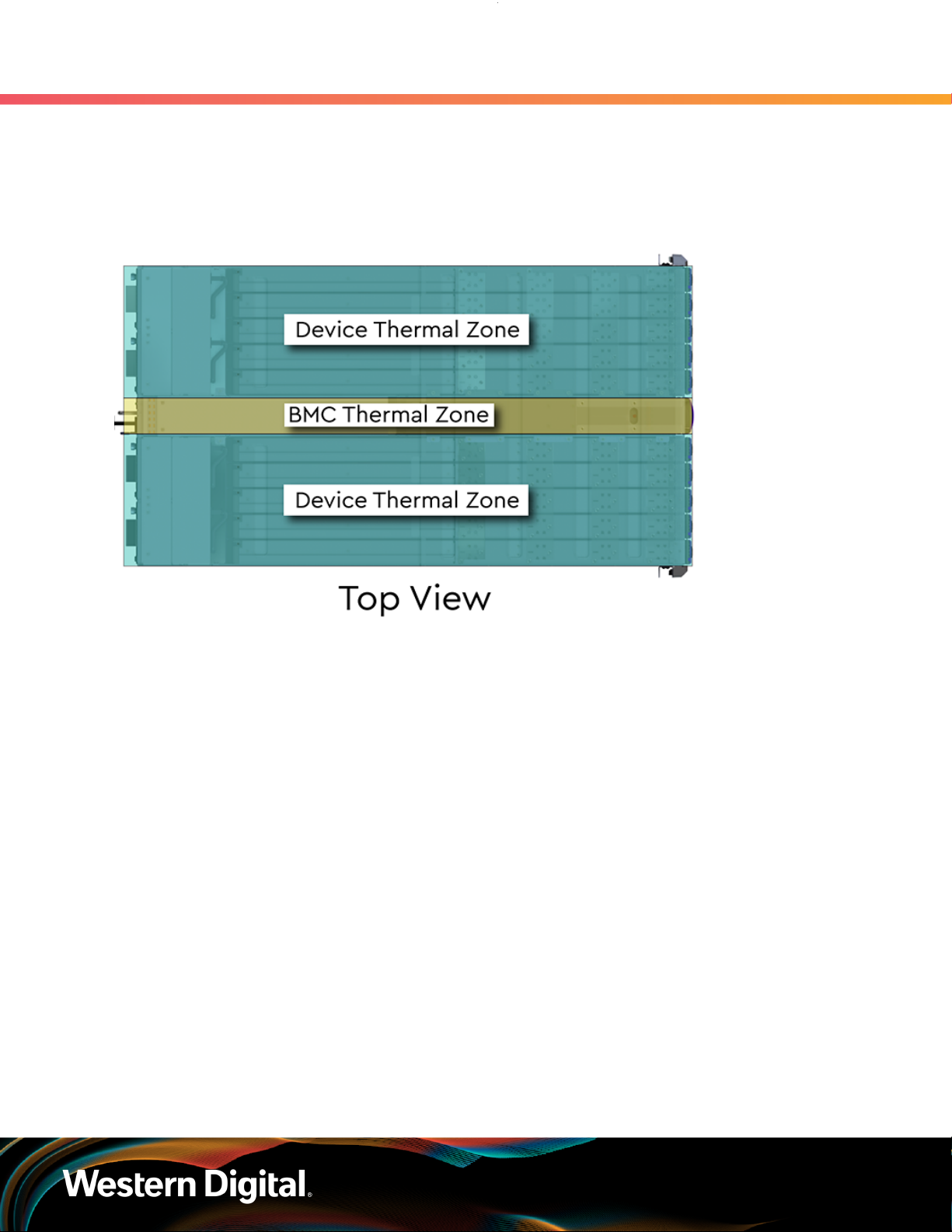
The following image displays the thermal zones as viewed from the top of the enclosure. When viewing
the enclosure from the front, the right device zone is on the right-hand side and the left device zone is
on the left-hand side. When viewing the enclosure from the rear, the order is reversed. Each of the two
thermal zones contains major components that are thermally maintained within their specific zone.
Figure 3: System Thermal Zones
1. Overview
1.2 System Architecture Overview
The E3000 uses a base algorithm, called a thermal algorithm, to control the overall thermal environment of
the system. The system is mechanically separated into two thermal zones to support efficient cooling of
the system components in order to achieve the intended performance of the system. The thermal zones
are split into device zones (the left and right side of the enclosure) and center zone when standing at the
front of the system. The device thermal zones contain up to ten devices or device blanks each that are
cooled by four fan modules that are located directly behind the devices. The four fan modules behind the
devices maintain the cooling for devices contained within the device slot installed into A through J. The
center thermal zone contains the BMC module that is cooled by the fans contained in the redundant PSUs
the are located directly behind the BMC module. The different thermal zones are designed to maintain
proper thermal cooling across the entire system. During servicing the system increases the speed of the
fan modules and PSU fans to maintain a balanced thermal load.
1.2.2.1 System Thermal Algorithm
The System Thermal Algorithm is designed to use temperature sensors and defined thresholds to
determine if the algorithm will select critical, increase, decrease, or no change as the device decision.
The System Thermal Algorithm uses the concept of priorities to ensure the proper function of the system.
As a result, any critical fault results in the system ramping the fans to maximum RPMs to protect the
hardware for the duration of the fault. The fault will remain in a critical state until the fault is fully resolved
and by bringing the temperature back within the specified defined thresholds.
6
Page 14

User Guide
The System Thermal Algorithm contains minimum and maximum thresholds related to the ambient
temperature of the system. The system is designed to maintain a maximum ambient temperature of 35°C.
Exceeding 35°C may result in damage to the hardware and potentially void the product warranty. These
thresholds allow for the best possible operating conditions. If the system goes outside of the minimum or
maximum threshold window, the BMC will adjust the fan speed to accommodate the issue and a fault will
be reported. The following table lists the Thermal Algorithm Thresholds along with the related fault levels
and threshold values.
The following table lists the different severity of thermal algorithm critical faults that are reported to the
user.
Table 2: Thermal Algorithm Critical Faults
1. Overview
1.3 Electrical Specifications
Component Critical Faults
Device Any sensor >= critical
BMC
The following table lists the device decision values that the system chooses from during operation. It
describes how the pulse width modulation (PWM) of the power that is being distributed to the cooling
fans reacts to different fault types.The fault will be reported based on the severity of the thermal issue.
Not installed FAN
Not installed PSU
Not installed Device or Blank
Not installed BMC
Any sensor >= criticalPSU
Any critical status on SMBus
Table 3: Thermal Algorithm Device Decision for Fan Control
Fault Sensor Value Fan Response
Critical Sensor >= Critical 100% PWM
Increase Sensor >= Max PWM + increase step
Decrease Sensor <= Min PWM - decrease step
No Change Min < Sensor < Max Hold PWM
1.3 Electrical Specifications
Table 4: Electrical Specifications
Specification Value
Max Power Consumption 1600W
Typical Power Consumption ~1400W
Input Voltage 200V - 240V
PSU Connector Type C16
7
Page 15

User Guide
Specification Value
Inrush Current Maximum (per PSU) AC line inrush current shall not exceed 40A peak,
PSU Efficiency 80 PLUS Platinum
1.4 Environmental Specifications
Table 5: Environmental Specifications
Specification Non-Operational Operational
Temperature -30°C to 60°C 5°C to 35°C
Temperature Gradient 30°C per hour max 20°C per hour max
Temperature De-rating 1°C per 300m above 3000m 1°C per 175m above 950m
1. Overview
1.4 Environmental Specifications
for up to one-quarter of the AC cycle after which,
the input current should be no more than the
specified maximum input current.
Relative Humidity 5-95% Non-Condensing 8-85% Non-Condensing
Relative Humidity Gradient 30% per hour maximum 30% per hour maximum
Altitude -300m to 12,000m / -984 ft. to
39,370 ft
Cooling N/A 4 Fan Modules (N+1 Supported),
1.5 Mechanical Specifications
Table 6: Mechanical Specifications
Specification Non-Operational Operational
Shock 20G, 7ms half sine; 3 positive
and 3 negative pulses in each
axis Z and Y. X axis- 15G, 7ms half
sine, 3 positive and 3 negative
pulses
Vibration Linear Random: 0.17G, 0 -
peak swept sine; 5 - 500Hz; 1
complete sweep @ 1/2 octave
per minute, ~13 minutes each
axis in X, Y, and Z
Linear Random: 0.50Grms;
5-500Hz; 10 minutes each axis in
X, Y, and Z
Linear Random: 0.54Grms;
1-200Hz; 60 minutes each axis in
X, Y, and Z
-300m to 3048m / -984 ft. to 10,000
ft.
containing two fans per module
5G, 11ms half sine; 3 positive and
3 negative pulses in each axis
X, Y, and Z. Minimum 6 seconds
between shocks
Linear Random: 0.15Grms; 5 500Hz; 10 minutes each axis in
X, Y, and Z
Swept Sine:0.17 G, 0 - peak,
5-500 Hz 0.5 octaves/min,
approx. 13 minutes each axis
8
Page 16

User Guide
Weight 107.04 kg / 236 lbs.
Dimensions W: 448.8 mm x L: 1000 mm x H: 176.7 mm / W: 17.6 in. x L: 39.4 in. x
System Installation Length 1000 mm / 39.4 in. from the front rack chassis mounts to the rear of
Required Rack Depth 1000 mm / 39.4 in. of usable rack space, frame to frame
Required Rack Width 450mm (17.72in.) with 465mm (18.31in.) ± 1.5mm nominal hole
Rack Units (U) 4U
Vertical Rack Rail Spacing 718 mm – 850 mm / 28.26 in. – 33.46 in.
1. Overview
1.6 Performance Specifications
Specification Non-Operational Operational
Swept Sine: 0.50G, 0 - peak
swept sine; 5 - 500Hz; 1
complete sweep @ 1/2 octave
per minute
H: 6.9 in.
the system
spacing. See EIA-310 Rack Standard
Table 7: Acoustic Specifications
Quantities Declared
A-weighted sound power level1, L
WAd
{1 B = 10
Idle
Mode
8.5 8.5 9.6 9.6
dB}
Average A-weighted emission sound pressure
level2, L
(dB) {bystander position3}
pAm
66.0 66.0 74.9 76.2
Statistical adder for verification4, K (dB) 2.5 2.5 2.5 2.5
Notes on Acoustic Testing Methodology and Environment:
• Background noise: <7dBA
• Environmental test conditions: ~23° C, 57% RH, 101.3 kPa
• Tested configuration: 3U NVMeOF VBOF device with 10 devices installed.
1
Declared A-weighted sound power level for a single machine, calculated per section 4.4.2 of ISO
9296-1988 and measured per ISO 3744
2
Declared A-weighted sound pressure level for a single machine, calculated per section 4.4.4 of
ISO-9296-1988 and measured per ISO 3744
3
The front and rear of the UUT were selected for the bystander location due to access typically from the
cool or hot isle in a data center. This does not meet the four bystander positions as specified in ECMA-74
2012, but the microphones were adjusted to the preferred location.
4
The statistical adder, K, accounts for random measurement error, and is equal to 2.5 dB, which is
appropriate for a 5% risk of rejection for SR = 1.5 dB per section 4.4.2 of ISO 9296-1988.
5
At steady state condition, system/PSU fans reached 100% pwm speeds during fan fail mode testing.
Operating
Mode
Fan Fail
Mode
5
Max Fan
Mode
1.6 Performance Specifications
9
Page 17

User Guide
Table 8: Performance Specifications
Number of Device Slots 10 Dual-port Fabric Device Bays
Data Transfer Rates 12GBps NVMe-oF
Max Raw Data Storage Capacity 614TB
Ethernet Ports 20 x 50Gbps QSFP28 ( 2 per Fabric Device)
Table 9: F3000 Performance Specifications by CRU P/N
1. Overview
1.6 Performance Specifications
Specification Value
4
1 x 10/100/1G Ethernet
CRU P/N
Capacity/
Endurance
Random Read
(4KB, QD=1024)
Random Write
(4KB, QD=1024)
Random Mixed
70R/30W
(4KB, QD=1024)
Sequential Read
(128KB, QD=320)
Sequential Write
(128KB, QD=320)
Random Write Latency
(4KB, QD=1, 99.99%)
1
Queue depth for 61.4TB device optimized at 1536, not 1024 as stated for other capacities
Notes on Performance Testing:
• Latency measured through a single Mellanox SN2700 switch
• K IOPs = IOPs x 1000
• Devices pre-conditioned with 2 full sequential fills
1EX1906/
1EX1910
12.8TB
3DWPD
2021K
IOPs
918K
IOPs
1570K
IOPs
11.9 GB/s 11.9 GB/s 11.9 GB/s 11.9 GB/s 11.9 GB/s
9.3 GB/s 9.3 GB/s 10.2 GB/s 10.2 GB/s 11.7 GB/s
107 µs 114 µs 75.3 µs 76.3 µs 48.9 µs
1EX1907/
1EX1911
15.4TB
1DWPD
2021K
IOPs
919K
IOPs
1537K
IOPs
1EX1908/
1EX1912
25.6TB
3DWPD
2004K
IOPs
609K
IOPs
1194K
IOPs
1EX1909/
1EX1913
30.7TB
1DWPD
2002K
IOPs
608K
IOPs
1194K
IOPs
1EX1914
61.4TB
1DWPD
2220K
1
IOPs
2420K
1
IOPs
2253K
IOPs
Table 10: F3100 Performance Specifications by CRU P/N
CRU P/N 1EX2413 1EX2416 1EX2414 1EX2417 1EX2415 1EX2418
Capacity/
Endurance
Random Read
(4KB, QD=1024)
4. Max storage capacity depends on device version and device configuration.
12.8TB
2DWPD
2199K
IOPs
15.4TB
0.8DWPD
2111K
IOPs
25.6TB
2DWPD
2164K
IOPs
30.7TB
0.8DWPD
2160K
IOPs
51.2TB
2DWPD
2176K
IOPs
61.4TB
0.8DWPD
2191K
IOPs
10
Page 18

User Guide
1. Overview
1.7 Physical Design
CRU P/N 1EX2413 1EX2416 1EX2414 1EX2417 1EX2415 1EX2418
Random Write
(4KB, QD=1024)
1493K
IOPs
1433K
IOPs
1431K
IOPs
1397K
IOPs
1464K
IOPs
1400K
IOPs
Random Mixed
70R/30W
(4KB, QD=1024)
Sequential Read
(128KB, QD=320)
Sequential Write
(128KB, QD=320)
Random Write
Latency
(4KB, QD=1, 99.99%)
Notes on Performance Testing:
• K IOPs = IOPs x 1000
• Devices pre-conditioned with 2 full sequential fills
2199K
IOPs
11.8 GB/s 11.7 GB/s 11.7 GB/s 11.7 GB/s 11.7 11.7 GB/s
9.9 GB/s 9.9 GB/s 9.9 GB/s 9.4 GB/s 9.4 GB/s 9.9 GB/s
33.9 µs 33.7 µs 33.7 µs 33.9 µs 33.7 µs 33.5 µs
2137K
IOPs
2183K
IOPs
Table 11: F3200 Performance Specifications by CRU P/N
CRU P/N 1EX2513 1EX2516 1EX2514 1EX2517 1EX2515 1EX2518
Capacity/
Endurance
Random Read
(4KB, QD=1024)
12.8TB
2DWPD
2218K
IOPs
15.4TB
0.8DWPD
2209K
IOPs
25.6TB
2DWPD
2212K
IOPs
2188K
IOPs
30.7TB
0.8DWPD
2210K
IOPs
2227K
IOPs
51.2TB
2DWPD
2221K
IOPs
2251K
IOPs
61.4TB
0.8DWPD
2214K
IOPs
Random Write
(4KB, QD=1024)
Random Mixed
70R/30W
(4KB, QD=1024)
Sequential Read
(128KB, QD=320)
Sequential Write
(128KB, QD=320)
Random Write
Latency
(4KB, QD=1, 99.99%)
Notes on Performance Testing:
• K IOPs = IOPs x 1000
• Devices pre-conditioned with 2 full sequential fills
1.7 Physical Design
2130K
IOPs
2292K
IOPs
11.5 GB/s 11.5 GB/s 11.5 GB/s 11.5 GB/s 11.5 GB/s 11.5 GB/s
11.5 GB/s 11.5 GB/s 11.5 GB/s 11.5 GB/s 11.5 GB/s 11.5 GB/s
38.5 µs 38.1 µs 38.1 µs 38.0 µs 46.7 µs 38.1 µs
1998K
IOPs
882K
IOPs
2124K
IOPs
2256K
IOPs
2129K
IOPs
2252K
IOPs
1930K
IOPs
2308K
IOPs
1907K
IOPs
2285K
IOPs
11
Page 19
User Guide
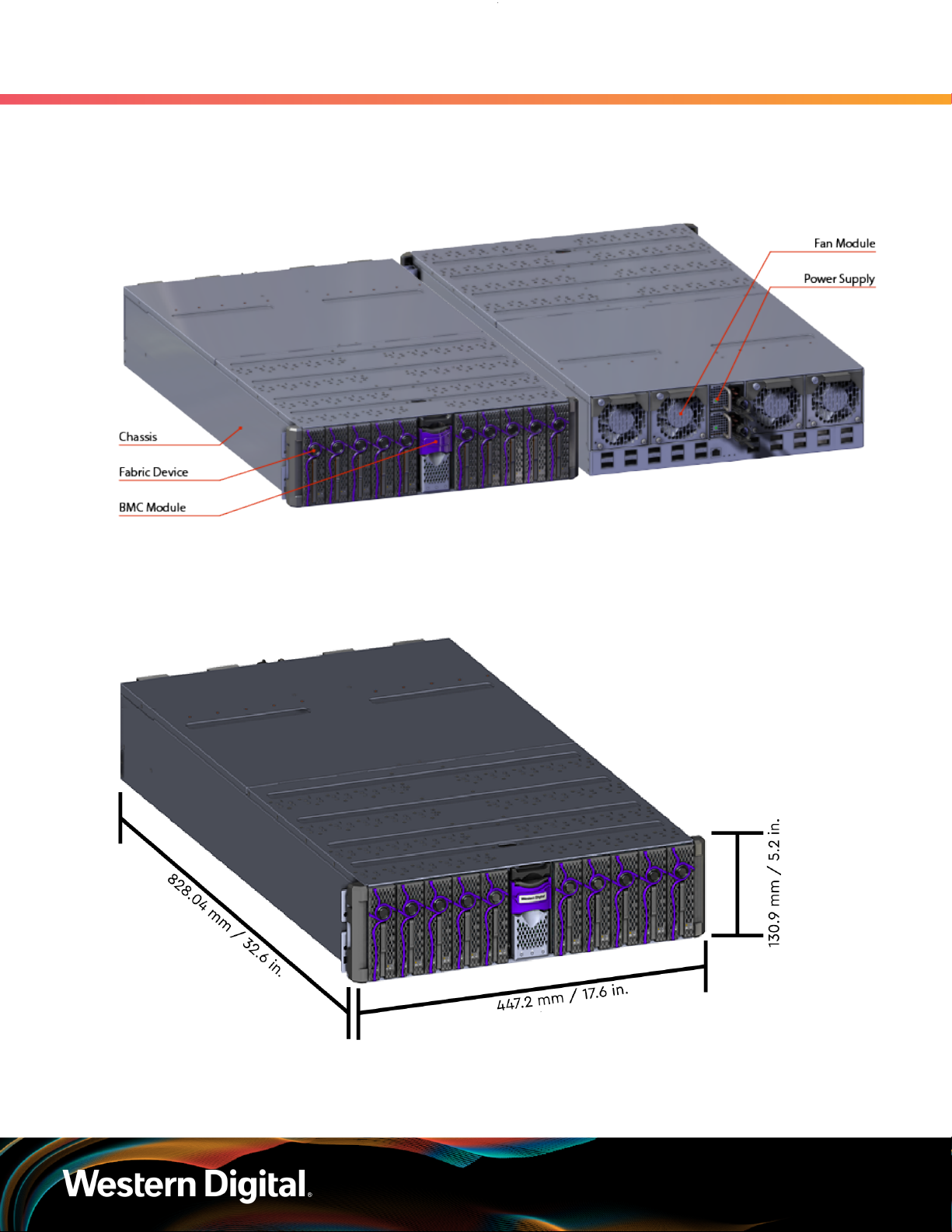
The OpenFlex F3x00 and E3000 physical design emphasizes easy access to hot-swappable components,
maximization of data storage capacity in the rack, and bold aesthetic design.
Figure 4: OpenFlex F3x00 and E3000 Layout
1. Overview
1.7 Physical Design
The enclosure measures 447.2 mm/17.6 in. wide by 828.04 mm/32.6 in. long. It's height is 130.9 mm/5.2 in.
or 3U. The chassis installation length is 778 mm (30.6 in.) from front rack chassis mounts to rear of system.
Figure 5: OpenFlex F3x00 and E3000 Dimensions
12
Page 20
User Guide
1.7.1 LEDs
Chassis LEDs
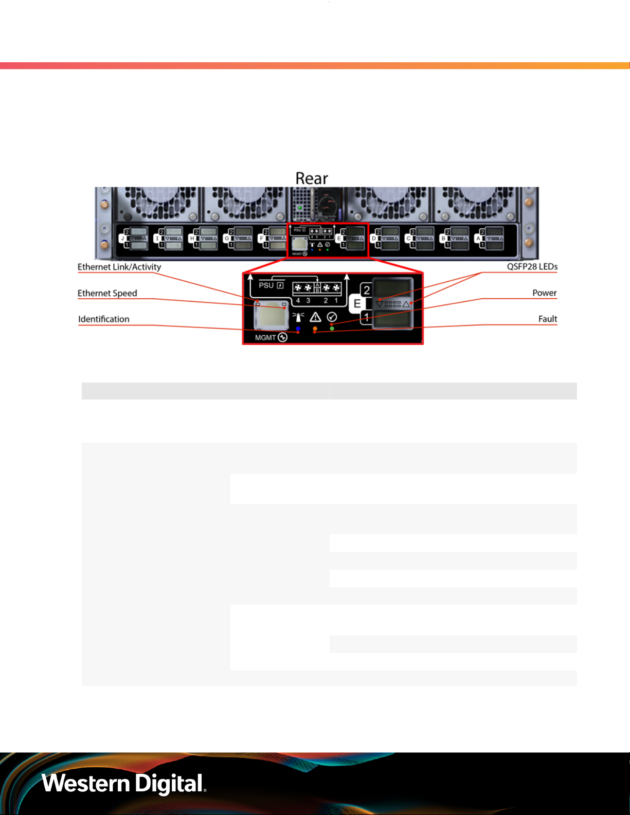
Figure 6: Chassis Rear IO LEDs
1. Overview
1.7 Physical Design
Table 12: Chassis Rear IO LED Flash Patterns
LED Name Color Behavior
Ethernet Link/Activity Green Solid On: Connected
Blink: Activity
Off: No Connection
Ethernet Speed
Identification Blue
QSFP28 LED
Green Solid On : Operating at 100 Mbps
Off: Operating at 10 Mbps
Amber Solid On: Operating at 1 Gbps
Off: Operating at 10 Mbps
Blink @ 1 Hz: Enclosure or any component being
identified (fans, PSUs, etc.)
Off: Enclosure/components not being identified
Green
Amber
Solid On: Link operating at maximum speed
Blink @ 3 Hz: Link activity
Off: Default state
Solid On: Link operating at a lower speed, 50G
or less
Blink @ 3 Hz: Low speed link activity
Blink @ 1 Hz: On/Off - Identify
Power Green Solid On: Enclosure is powered on
13
Page 21
User Guide
PSU LED
1. Overview
1.7 Physical Design
LED Name Color Behavior
Off: Enclosure is powered off
Fault Amber Solid On: Enclosure is not ready or BMC is not
present
Blink @ 2 Hz: Enclosure has a fault
Off: Enclosure has no fault
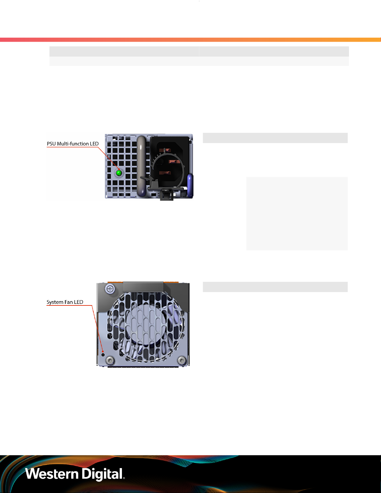
Figure 7: PSU LED
Fan Module LED
Figure 8: Fan Module LED
Table 13: PSU LED Flash Patterns
LED Name Color Behavior
Multi-
function LED
Table 14: Fan Module LED Flash Patterns
LED Name Color Behavior
LED Amber Solid On: Fan reporting
Green Solid On: PSU on and
reporting no faults
Off: PSU disconnected
from power
Amber Solid On: PSU
disconnected from
power or critical fault,
causing shutdown
failure
Blink @ 1 Hz: PSU
reporting fault
Off: PSU reporting no
fault
fault
Blink @ 1 Hz: Fan
being identified
Off: Fan on and
reporting no fault
14
Page 22
User Guide
BMC Module LEDs
1. Overview
1.7 Physical Design
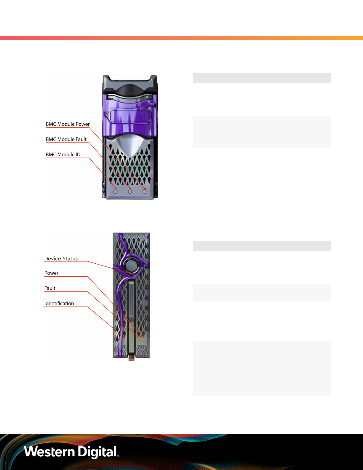
Figure 9: BMC Module LEDs
OpenFlex F3x00 LEDs
Figure 10: OpenFlex F3x00 LEDs
Table 15: BMC Module LED Flash Patterns
LED Name Color Behavior
Identification Blue Blink @ 1 Hz: BMC or
any component being
identified (fans, PSUs,
etc.)
Fault Amber Blink @ 2 Hz:
Enclosure reporting
fault
Off: Default State
Power Green Solid: Powered On
Table 16: OpenFlex F3x00 LED Flash
Patterns
LED Name Color Behavior
Device Status White Solid On: Powered on
and connected
Off: Not ready or
powered down
Power Green Solid On: Powered on
Off: Powered down
Fault Amber Solid On: Device
powered down
Blink @ 1 Hz: Device
reporting fault
Off: Device has no fault
Identification Blue Solid On: Device
shutting down or
powering on
Blink @ 1 Hz: Device
being idendified
Off: Device not being
identified
15
Page 23

User Guide
1.7.2 Cables
Approved Power Cables
Table 17: Compatible Passive Cables
1. Overview
1.7 Physical Design
Type Part Number Length
IEC C14 to IEC C15 Heavy
Duty 15A Power Cable
Note: The following Ethernet cables are compatible with the OpenFlex F3x00 and E3000 but
are not provided by Western Digital.
Manufacturer Model Length Speed
Mellanox
MCP1600-C001 Direct Attach Cable 1m 100Gb/s
MCP1600-C002 Direct Attach Cable 2m 100Gb/s
(Provided in Accessory Kit) 6 ft.
MCP1600-C002E26N Direct Attach Cable 2m 100Gb/s
MCP1600-C002E30N Direct Attach Cable 2m 100Gb/s
MCP1600-C003 Direct Attach Cable 3m 100Gb/s
MCP7H00-G001 Direct Attach Splitter Cable 1m 2 x 50Gb/s
MCP7H00-G003 Direct Attach Splitter Cable 3m 2 x 50Gb/s
Amphenol
NDARHG-0001 Direct Attach Cable 1m 100Gb/s
NDARHG-0002 Direct Attach Cable 2m 100Gb/s
NDARHG-0004 Direct Attach Cable 4m 100Gb/s
NDARHJ-0003 Direct Attach Cable 3m 100Gb/s
NDARHJ-0005 Direct Attach Cable 5m 100Gb/s
Table 18: Compatible Active Cables
Manufacturer Model Length Speed
Mellanox
MFA1A00-C005 Active Optical Cable 5m 100Gb/s
MFA7A20-C003 Active Optical Cable 3m 100Gb/s
MFA7A20-C010 Active Optical Cable 10m 100Gb/s
16
Page 24

User Guide
1.8 Restrictions and Limitations
The OpenFlex F3x00 and E3000 have the following restrictions and limitations on functionality:
• The E3000 chassis must be full for proper airflow. If there is only one F3x00 storage device installed, the
rest of the slots must be filled with device blanks.
• If the BMC Module is not installed in the E3000 chassis, F3x00 devices cannot be added or slotswapped. In the absence of BMC Module, the LEDs may not function as designed.
• Only hot-swap a single device at a time. Never remove more than one at a time. Both PSUs must be
functional in order to detect new hot-plugged F3x00s.
• The F3x00 storage device does not support RoCE v1; it supports RoCE v2 only.
• Powering on an F3x00 storage device must be accomplished through the E3000 chassis (via its GUI)
that contains it, but powering off an F3x00 can be accomplished from the storage device itself (via its
GUI).
• The F3x00 storage device data ports support IPv4 networking only.
• The E3000 chassis device management port supports both IPv4 and IPv6 networking.
• The E3000 chassis device does not support DNS configuration or administration.
• Only one browser session is allowed to an individual F3x00 storage device at a time.
•
Enforced maximum limits on configuration:
◦ 256 Volumes
◦ 256 Hosts
◦ 2048 Queue Pairs
◦ 128 Queue Pairs (1 Admin, 127 IO) per connection
◦ 64 max. queue depth per IO Queue Pair
◦ 8 VLANs per F3x00 storage device
1. Overview
1.8 Restrictions and Limitations
1.9 Site Requirements
1.9.1 Power Requirements
The E3000 is equipped with redundant power supply units. The PSUs are hot-swappable and are located
at the rear of the chassis. The following is a power specification summary. Note that the system does not
support low-line voltage.
Table 19: Power Specification Summary
Specification Value
Power Output 1600W
Input Voltage 200V - 240V
80 PLUS Standard Platinum
Connector Type C16
1.9.2 Rack Requirements
17
Page 25

User Guide
The E3000 is designed to be installed into a rack that meets the EIA-310 standard with a minimum of 1000
mm (39.4 in.) of usable rack space, frame to frame. The vertical rack rails must be set between 718 mm
(28.26 in.) – 850 mm (33.46 in.) to support the enclosure. It requires 3U of rack space, and it should be
installed into the rack at the lowest possible U height to keep the load on the rack balanced.
Table 20: Required Rack Specifications
1. Overview
1.9 Site Requirements
Parameter Requirement
Rack Depth 1000 mm (39.4 in.) of usable rack space, frame to
frame
Rack Width 450mm (17.72in.) with 465mm (18.31in.) ± 1.5mm
nominal hole spacing. See EIA-310 Rack Standard
Rack Units (U) 3U
Vertical Rack Rail Spacing 718 mm (28.26 in.) – 850 mm (33.46 in.)
Static Load Rating Rack meets ISTA 3E or 3B test requirements and
regulations when mounted to the shipping pallet
Dynamic Load Rating Rack meets ISTA 3E or 3B test requirements and
regulations when mounted to the shipping pallet
1.9.3 Thermal and Cooling Requirements
The thermal output of the enclosure depends on the number of F3x00s that are populated in the E3000
chassis. Use the following table to determine how many BTUs of heat will exhaust from the rear of the unit.
Table 21: BTU Exhaust per Component
Condition Typical BTU Output Max BTU Output
Single E3000 with BMC Module 768 BTU/hr = 225 W
(25C/77F, fans at 50%)
Single F3x00 409 BTU/hr = 120 W
(25C/77F, Workload: Random
Read/Write, queue depth
32, 80% internal processors
dedicated to workload)
E3000 Fully Populated with
F3x00s
5244 BTU/hr = 1537 W
(25C/77F, fans at 50%)
1177 BTU/hr = 345 W
(35C/95F, fans at 100%)
546 BTU/hr = 160 W
(35C/95F, Workload: Highest
throughput to drives – Seq
Write, queue depth 32, all
internal processors at 100%)
5884 BTU/hr = 1725 W
(35C/95F, fans at 100%)
1.9.4 Installation and Servicing Requirements
18
Page 26
User Guide
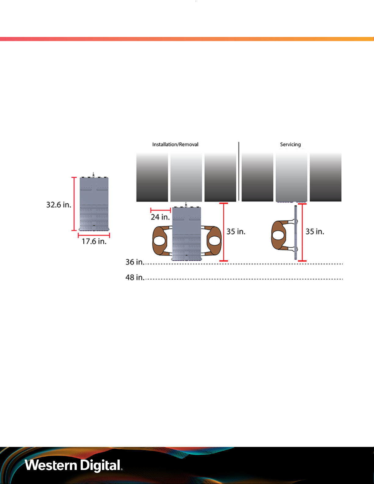
Space Requirements
Installation of the OpenFlex F3x00 and E3000 requires two people and enough space in front of the rack
for a safe installation. The recommended forward clearance is 889 mm / 35 in. from the front of the rack
and 609.6 mm / 24 in. on both sides of the enclosure. It is also recommended to make considerations for
any carts or lift equipment that might be used to perform the installation.
Servicing of the OpenFlex F3x00 and E3000 requires one person and a minimum of 889 mm / 35 in. of
space in front of the rack to allow enough clearance to remove an F3x00 from the enclosure.
The following diagram provides measurement details for installation and servicing:
Figure 11: Installation and Servicing Space
1. Overview
1.9 Site Requirements
5
5. The weight of the enclosure during installation will vary, depending on the number of F3x00 devices and blanks contained
in the E3000. In some situations, carts or lift equipment may be required.
19
Page 27

Western Digital
Components
In This Chapter:
- Chassis........................................................... 21
- PSU.................................................................22
- Fan Module....................................................23
- BMC Module..................................................24
- Rails................................................................25
- OpenFlex F3x00............................................26
- OpenFlex E3000 Fabric Device Blank.........27
- List of Field/Customer Replaceable
Units................................................................ 28
20
Page 28
User Guide
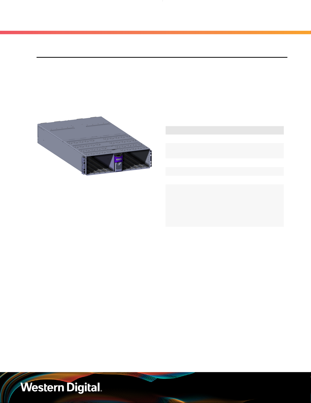
2.1 Chassis
The OpenFlex E3000 chassis is the primary housing that contains and connects all of the system
components that comprise the OpenFlex F3x00 and E3000 . The chassis contains ten device slots and one
BMC Module slot on the front, and the rear contains slots for the redundant PSUs and four Fan Modules. The
OpenFlex F3x00 and E3000 is installed and secured onto shelf style rail mounts. The rear IO houses the
primary connections such as power and QSFP28 ports and the status LEDs for all of the components.
2.1.1 Chassis Specifications
2. Components
2.1 Chassis
Table 22: Chassis Specification Summary
Specification Value
Rack Units 3U
Number of
Device Slots
Number of BMC Slots 1
Part Number 1EX1919
Hot Swappable? No
Dimensions
Weight 17.32 kg / 38.2 lbs
W: 447.2 mm x
L: 828.04 mm
x H: 130.9 mm
W: 17.6 in. x L:
32.6 in. x H: 5.2 in.
10
21
Page 29
User Guide
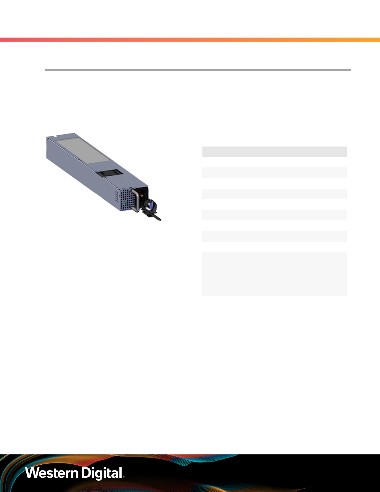
2.2 PSU
The OpenFlex E3000 chassis contains toolless redundant 1600W Power Supply Units (PSU). Each PSU
requires an input voltage of between 200V - 240V. The PSUs are certified 80 PLUS Platinum and use the C16
connector type. Due to the redundant nature of the PSUs, they may be serviced or replaced, one at a time,
while the enclosure is powered on.
2.2.1 PSU Specifications
2. Components
Table 23: PSU Specification Summary
Specification Value
Power Output 1600W
Input Voltage 200V - 240V
80 PLUS Standard Platinum
Connector Type C16
2.2 PSU
Internal Fan Speed Up to 25,000 RPM
Number per Enclosure 2
Part Number 1EX1916
Hot Swappable? Yes
Service Window 5 minutes
Dimensions
Weight 1.05 kg / 2.31 lbs.
W: 54.5 mm x L: 321.5
mm x H: 40.1 mm
W: 2.15 in. x L: 12.66
in. x H: 1.58 in.
22
Page 30
User Guide
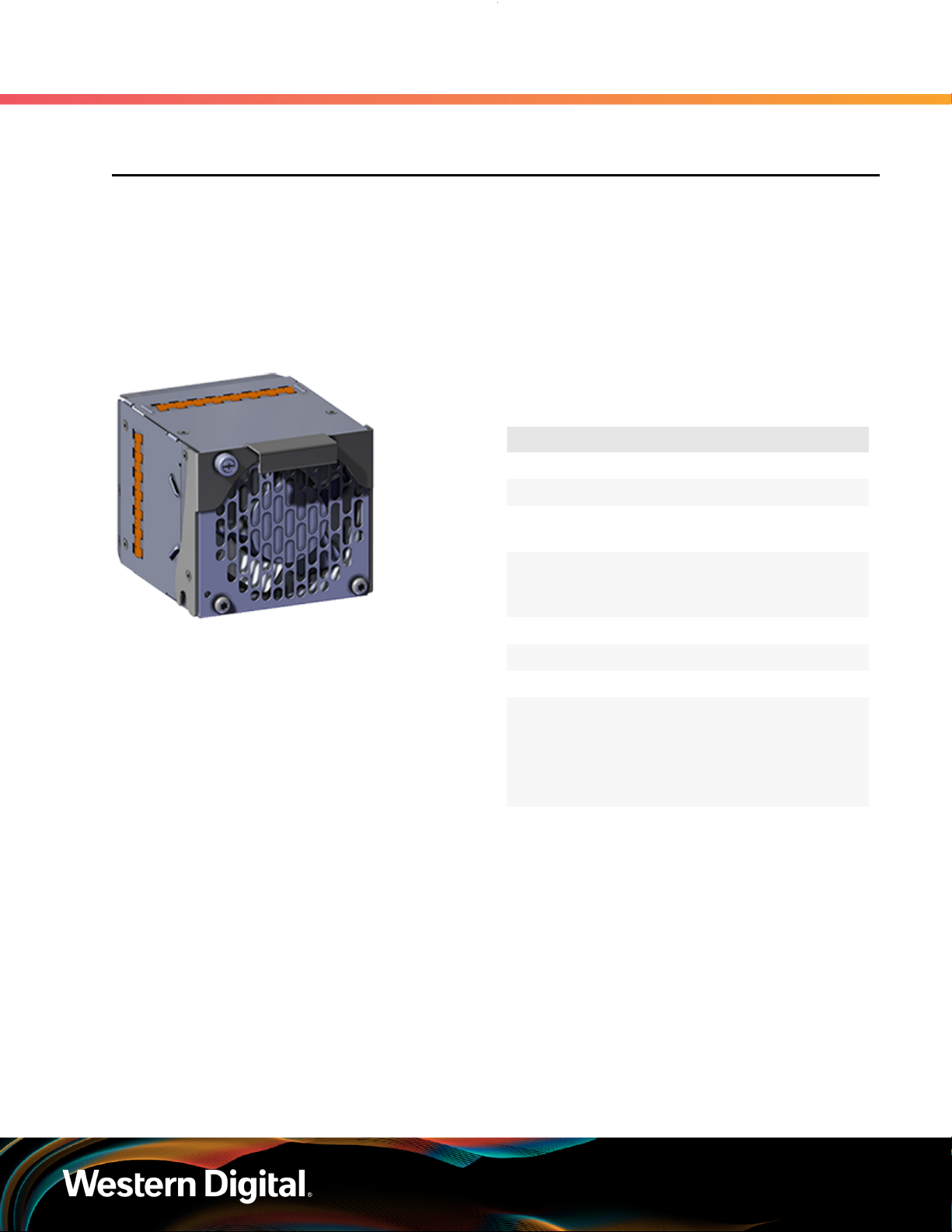
2.3 Fan Module
The OpenFlex E3000 contains four toolless Fan Modules to maintain the cooling across the entire system.
The Fan Modules are connected to the rear of the Chassis using a handle to seat the module in place and a
captive screw to secure the Fan Module into the fan bay. Due to the redundant nature of the Fan Modules,
they may be serviced or replaced, one at a time, while the enclosure is powered on. The Fan Modules
will accelerate to the maximum RPM while the BMC Module or devices are removed during servicing or
replacement.
2.3.1 Fan Module Specifications
2. Components
2.3 Fan Module
Table 24: Fan Module Specification
Summary
Specification Value
Rated Voltage 12V
Fan Speed 12000 RPM
Acoustics 76 dB measured at 1
meter from the fan inlet
Number per Enclosure 4 Fan Modules
containing two
rotors per module
Part Number 1EX1915
Hot Swappable? Yes
Service Window 5 minutes
Dimensions
Weight 0.8 kg / 1.76 lbs.
W: 92.74 mm x L: 127.2
mm x H: 85.2 mm
W: 3.65 in x L:
5.01 in x H: 3.35 in
23
Page 31

User Guide
2.4 BMC Module
The OpenFlex E3000 contains a toolless BMC Module that is installed into the center slot at the front of
the Chassis. The BMC Module is accessed using a 1G Ethernet management RJ45 port on the rear IO of the
Chassis. The BMC Module enables out of band management (OOBM) using a RESTful interface (via HTTP
or HTTPS). OOBM controls the actions between devices and the BMC Module for powering down, setting
system configurations, and the cooling algorithm for the Fan Modules. The BMC Module may be serviced or
replaced while the enclosure is powered on as long as it is replaced within five minutes of removing it from
the slot.
2.4.1 BMC Module Specifications
2. Components
2.4 BMC Module
Table 25: BMC Module Specification
Summary
Specification Value
Input Current 2A Maximum
Input Power 25W
Rated Voltage 12V +/- 10%
Number per Enclosure 1 installed in the
center device slot
Part Number 1EX1917
Hot Swappable? Yes
Service window 5 minutes
Dimensions
Weight 1.48 kg / 3.26 lbs.
W: 55.6 mm x L: 459.12
mm x H: 126.94 mm
W: 2.19 in x L:
18.08 in x H: 5 in
24
Page 32

User Guide
2.5 Rails
The E3000 is installed onto shelf style rails. The rail length can be adjusted between 850.31 mm / 33.47
in (max) and 693.69 mm / 27.31 in. (min) in order to fit into different vertical rack rail settings. Once the
enclosure is installed onto the rails, it may be secured to the rails using the provided M5 screws.
2.5.1 Rails Specifications
2. Components
Table 26: Rails Specification Summary
Specification Value
Length 693.69 mm
/ 27.31 in. (min)
850.31 mm
/ 33.47 in (max)
Part Number 1EX2198
2.5 Rails
Hot Swappable? No
Dimensions
Weight 5.08 kg / 11.2
W: 34.4 mm x L: 693.69
mm x H: 89.65 mm
W: 1.35 in. x L: 27.31
in. x H: 3.53 in.
lbs (both rails)
25
Page 33

User Guide
2.6 OpenFlex F3x00
The F3x00 is a fabric device that contains a maximum of 61.4TB of raw data storage capacity per device. The
device supports Open Composable Infrastructure (OCI) through storage disaggregation using NVMe-overFabrics (NVMe-oF). The front of the F3x00 contains a button latch release system and status LEDs, and the
rear contains the device connector.
2.6.1 OpenFlex F3x00 Specifications
2. Components
2.6 OpenFlex F3x00
Table 27: OpenFlex F3x00 Specification
Summary
Specification Value
Max Raw Data Storage
Capacity per device
Data Ingest Capability 2x 50G Ethernet
Architecture (page 5))
61.4 TB
(see System High
Speed Data Ingest
Data Transfer Rates 12 GBps
Number per enclosure Up to 10
Part Numbers See Supported SKUs
(page 4) to find
the specific part
number required.
Hot Swappable? Yes
Service Window 5 minutes
Dimensions
Weight 4.44 kg / 9.8 lbs
W: 37.53 mm x L: 694.4
mm x H: 124.11 mm
W: 1.48 in x L:
27.34 in x H: 4.89 in
26
Page 34

User Guide
2.7 OpenFlex E3000 Fabric Device Blank
2.7 OpenFlex E3000 Fabric Device Blank
The OpenFlex E3000 chassis may contain up to 9 E3000 Fabric Device Blanks6. The chassis must contain at
least one device, and the remaining slots must be populated with either devices or device blanks to avoid
compromising the cooling of the enclosure. Each E3000 Fabric Device Blank may be replaced with a device
as the enclosure is scaled up. The E3000 Fabric Device Blank may be serviced or replaced one at a time
while the enclosure is powered on.
2.7.1 E3000 Fabric Device Blank Specifications
Table 28: E3000 Fabric Device Blank
Specification Summary
Specification Value
Number per enclosure Up to 9
Part Number 1EX1918
2. Components
Hot Swappable? Yes
Service Window 5 minutes
Dimensions
Weight 1.87 kg / 4.12 lbs.
W: 37.53 mm x L: 694.4
mm x H: 124.11 mm
W: 1.48 in x L:
27.34 in x H: 4.89 in
6. The form factor of the fabric device blank is compatible with all F-Series devices.
27
Page 35

User Guide
2.8 List of Field/Customer Replaceable Units
2.8 List of Field/Customer Replaceable Units
The following table lists the replaceable components and their part numbers.
Table 29: List of Field/Customer Replaceable Components
Component Part Number
Chassis 1EX1919
PSU 1EX1916
Fan Module 1EX1915
BMC Module 1EX1917
Rails 1EX2198
Accessory Kit 1EX2199
E3000 Fabric Device Blank 1EX1918
OpenFlex F3x00 Fabric Device See Supported SKUs (page 4)
2. Components
28
Page 36

Western Digital
Management
In This Chapter:
- OCGUI............................................................30
- Part Replacement........................................113
29
Page 37

User Guide
3.1 OCGUI
3.1.1 Compatible Browsers
The OCGUI is compatible with the following web browsers.
Table 30: OCGUI Browser Compatibility
3. Management
3.1 OCGUI
Browser Version
Google Chrome 71.0.3578.98 and higher
Mozilla Firefox 40.15063.674.0 and higher
Microsoft Edge 60.5.0 and higher
Note: The OCGUI is not compatible with Internet Explorer.
3.1.2 Login Page
The login page displays two panels. The left panel provides username and password fields for logging
into the device. The right panel lists basic information about the device itself, including its type, status, and
OS version.
Note: For instructions on navigating to the login page, see Navigating to a Device (page
50).
30
Page 38

User Guide
3.1.3 Dashboard
3. Management
3.1 OCGUI
The Dashboard is the first page that will load when one logs into any of the fabric-attached devices. It
provides vital statistics on the health and performance of all devices on the subnet configured on the BMC.
In addition, it provides a clickable list that allows users to navigate to the device page for any device on
the subnet.
3.1.3.1 System Health
The System Health section provides an overview of the health of the fabric network. The interfaces of
all devices on the same subnet as the chassis's BMC and Storage devices are queried when the page
loads, and the pie chart is updated with their responses. If fabric devices respond with errors or faults, the
system health chart will update accordingly.
31
Page 39

User Guide
Figure 22: System Health States
The System Health pie chart contains segments for grouping fabric devices by their health states.
Clicking on a segment will bring up a modal window that provides a summary of the devices in that state.
The following is a sampling of modal windows:
3. Management
3.1 OCGUI
3.1.3.2 System Utilization
32
Page 40

User Guide
The System Utilization section displays the total, free, and used storage on the fabric in TB.
3.1.3.3 System Performance
The System Performance section provides general, bitwise system performance information for all
devices on the fabric.
3. Management
3.1 OCGUI
3.1.3.4 Storage Health
33
Page 41

User Guide
The Storage Health modal provides an overview of the health of all storage devices visible on the
fabric (those in the subnets of what is configured on the chassis's BMC and storage devices). The modal
provides seperate tables for fabric devices that are presenting different health states up to the OCGUI.
3.1.3.5 Chassis Health
3. Management
3.1 OCGUI
The Chassis Health modal provides an overview of the health of all chassis devices visible on the fabric
(those in the subnets of what is configured on the chassis's BMC and storage devices). This status comes
from the BMC module installed in the chassis. The modal provides seperate tables for fabric devices that
are presenting different health states up to the OCGUI.
3.1.3.6 Devices
34
Page 42

User Guide
The Devices list provides summary details about all devices visible on the fabric. Users can also link to
the device page for the OpenFlex device of their choosing for management purposes. Vital information
is provided, such as the version of firmware code loaded on each device, the type of device that was
discovered, and the UUID. This list will be updated with each refresh of the page, as a query command
is sent across the fabric network to discover OpenFlex devices. The search field—located at the top of
the devices list—allows for users to access specific devices without having to review the list for specific
devices or device configurations.
3. Management
3.1 OCGUI
35
Page 43

User Guide
3.1.4 Storage Device Page
The storage device page presents all of the vital information related to a specific storage resource.
3.1.4.1 Storage Device Health
3. Management
3.1 OCGUI
The storage Device Health section provides a visual summary of the health of pools and volumes on the
device.
3.1.4.2 Storage Device Utilization
36
Page 44

User Guide
The storage Device Utilization section provides a visual summary of the available and used storage on
the device.
3. Management
3.1 OCGUI
3.1.4.3 Storage Device Performance
The storage Device Performance section provides a visual summary of the current IO performance of the
device.
3.1.4.4 Storage Device Information
37
Page 45

User Guide
3. Management
3.1 OCGUI
The storage Device Information section provides information about the device itself, such as the ID, Serial
Number, and performance statistics.
3.1.4.5 Storage Administration
The storage device's Administration section allows system administrators to perform important
management functions to the device.
3.1.4.6 Storage Accounts
38
Page 46

User Guide
The storage device's Accounts section provides a list of all accounts that can access the device.
3.1.4.7 Storage Location
3. Management
3.1 OCGUI
The storage device's Location section provides information about the physical location of the device.
3.1.4.8 Storage Ports
39
Page 47
User Guide
3. Management
3.1 OCGUI
The storage device's Ports section provides access to the networking settings for the ports that exist on
the device.
3.1.4.9 Storage Sensors
The storage device's Sensors section lists all the sensors present on the device hardware and reports the
readings from those sensors.
3.1.4.10 Storage Device OS
The storage Device OS section displays the device's firmware version and can be used to upgrade
firmware.
3.1.4.11 Storage Pools
40
Page 48

User Guide
The storage device's Pools section shows all of the pools configured on the storage device. The number
of pools can be set to 1, 2, 4, or 8.
3.1.4.12 Storage Volumes
3. Management
3.1 OCGUI
The storage device's Volumes section displays all of the volumes configured on the device and allows for
volumes to be added, modified, or deleted.
3.1.4.13 Storage Hosts
The storage device's Hosts section provides information on the hosts that are available to be connected
to storage and allows configuration of those hosts on the fabric.
41
Page 49

User Guide
3.1.4.14 Storage VLANs
The storage device's Virtual LANs (VLANs) section displays all of the VLANs that have been created on the
device and allows for VLANs to be created, modified, or deleted.
3.1.4.15 Storage Paths
3. Management
3.1 OCGUI
The storage device's Paths section lists all of the current paths available to the storage volumes. Paths
connect storage volumes to hosts and VLANs.
42
Page 50

User Guide
3.1.5 Chassis Device Page
The chassis device page presents all of the vital information related to a specific chassis resource.
3.1.5.1 Chassis Device Health
3. Management
3.1 OCGUI
The chassis's Device Health section shows a visual summary of the general health of devices on the
network.
3.1.5.2 Chassis Power Utilization
43
Page 51

User Guide
The chassis's Power Utilization section gives a summary of the sensor data that is being reported by the
power supplies. Charts display the current amps and volts being consumed by the system, as well as the
temperature.
3.1.5.3 Chassis Cooling Performance
3. Management
3.1 OCGUI
The chassis's Cooling Performance section displays the current RPMs at which the onboard cooling fans
are operating.
3.1.5.4 Chassis Device Information
44
Page 52

User Guide
3. Management
3.1 OCGUI
The chassis's Device Information section provides information about the device itself, such as the ID and
Serial Number.
3.1.5.5 Chassis Administration
The chassis's Administration section provides access to maintence and system administration functions.
3.1.5.6 Chassis Accounts
45
Page 53

User Guide
The chassis's Accounts section provides a list of all the accounts that can access the device.
3.1.5.7 Chassis Location
3. Management
3.1 OCGUI
The chassis's Location section provides information regarding the physical location of the device.
3.1.5.8 Chassis Power Supplies
The chassis's Power Supplies section provides health and status information of the power supplies
installed in the device.
3.1.5.9 Chassis Fans
46
Page 54

User Guide
The chassis's Fans section shows the status and health of all the fans installed in the device (2 rotors per
Fan Module, plus 2 PSU fans).
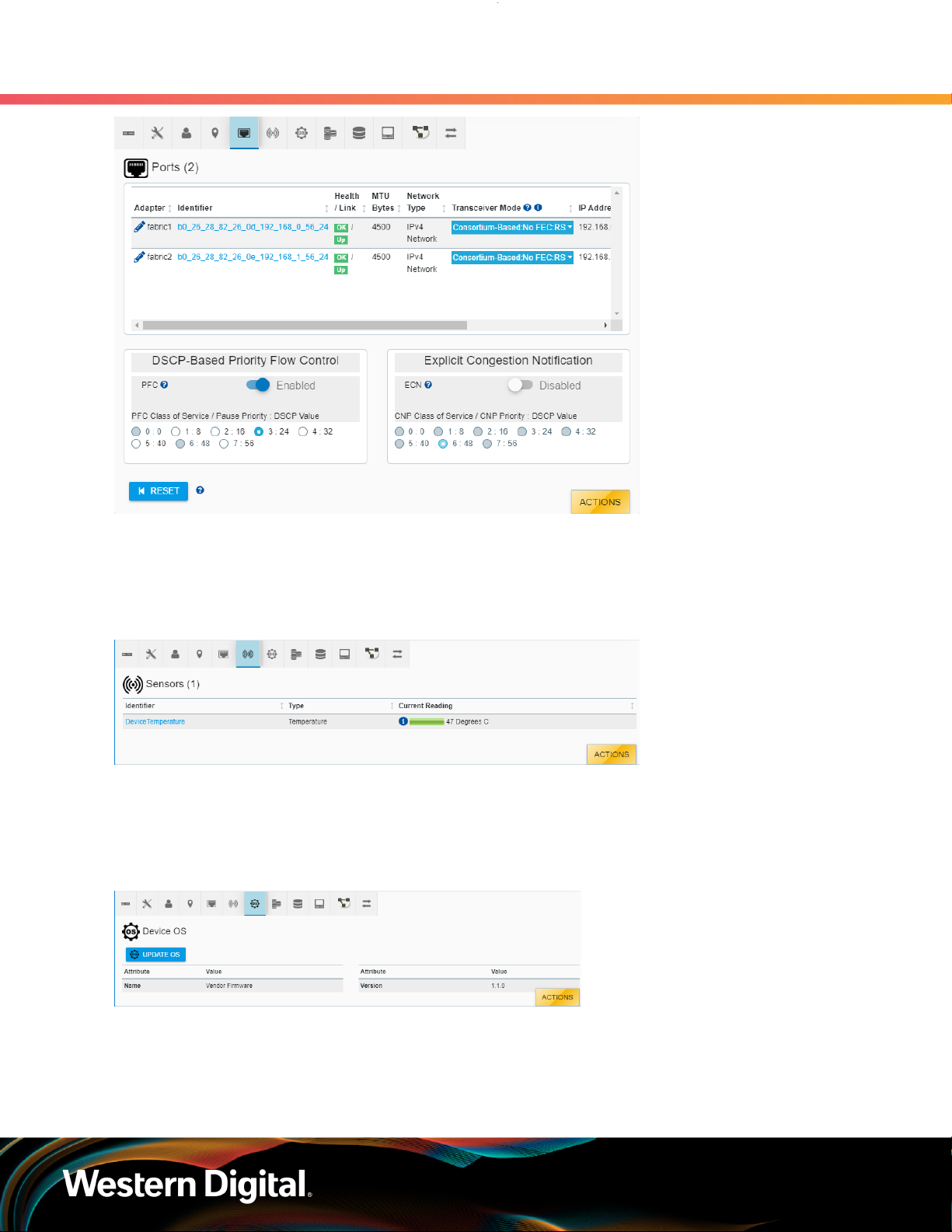
3.1.5.10 Chassis Ports
3. Management
3.1 OCGUI
The chassis's Ports section provides access to the networking settings for the ports that exist on the
device.
3.1.5.11 Chassis Sensors
47
Page 55

User Guide
3. Management
3.1 OCGUI
The chassis device's Sensors section lists all the sensors present on the chassis hardware and reports the
readings from those sensors.
3.1.5.12 Chassis Slots
The chassis's Slots section provides information about the devices installed in each slot.
3.1.5.13 Chassis Device OS
48
Page 56

User Guide
The chassis's Device OS section displays the firmware version and can be used to upgrade firmware.
3. Management
3.1 OCGUI
49
Page 57

User Guide
3.1.6 Basic Operational Functions
This section provides instructions for basic operational functions that the user is likely to perform during the
initial operation of the OpenFlex F3x00 and E3000 , such as checking the system health, creating a user
account, etc.
3.1.6.1 Navigating to a Device
This task provides instructions for using the OCGUI to navigate to a device's dashboard through any
other fabric-connected device.
Before you begin: The BMC's MAC address is listed on a label affixed to the module's side. This MAC
address can be used to determine the IP addresses assigned via DHCP to the OpenFlex E3000 chassis
and the F3x00 storage devices contained within it.
Figure 61: BMC Module MAC Address Label
3. Management
3.1 OCGUI
Step 1 : Open a browser and enter the IP address for any fabric-connected device into the address
bar.
The login page for the device appears:
Step 2 : Enter a valid username and password, and click the Login button:
50
Page 58

User Guide
3. Management
3.1 OCGUI
Note: The default username/password is admin/admin.
The system dashboard appears. In addition, the Devices section provides access to all other
fabric-connected devices:
Step 3 : If needed, click the Devices banner to expand the list of all connected devices:
Step 4 :
Step 5 : Click the Device Actions icon:
Step 6 : Click the Open in a new tab/window option to open the device page in a new window.
From the list, identify the device to which you want to navigate.
The Device Actions window appears:
51
Page 59

User Guide
3.1.6.2 Checking System Health
This task provides instructions for checking the health of the E3000 chassis device using the OCGUI,
including:
• Device Information
• Device Logs
• Power Supplies
• Fans
• Ports
• Sensors
• Slots
Checking the Device Information
3. Management
3.1 OCGUI
The device's dashboard appears in a new tab/window.
Step 1 :
Step 2 : Click the chassis's Device Information icon:
Navigate to the chassis device (see Navigating to a Device (page 50)).
The Device Information appears:
Step 3 :
Review the chassis's device information and ensure that its health status reports OK in the
header.
52
Page 60

User Guide
Checking the Device Logs
Step 4 : Click the Device Logs button:
3. Management
3.1 OCGUI
The Device Log Viewer appears:
Step 5 : Select one of the log types by clicking its radio button.
The Device Log Viewer updates to show the selected log information, which can then be
exported by clicking the Export button at the bottom of the viewer:
53
Page 61

User Guide
3. Management
3.1 OCGUI
Checking the Power Supplies
Step 6 : Click the chassis's Power Supplies icon:
The Power Supplies information appears:
Step 7 :
Checking the Fans
Step 8 : Click the chassis's Fans icon:
Review the chassis's power supply information and ensure that both PSUs report OK in the
Health column.
The Fans information appears:
54
Page 62

User Guide
3. Management
3.1 OCGUI
Step 9 :
Checking the Ports
Step 10 : Click the chassis's Ports icon:
Step 11 :
Review the chassis's fan information and ensure that each fan reports OK in the Health column.
The Ports information appears:
Review the chassis's port information and ensure that each port is reporting OK in the Health
column.
Checking the Sensors
Step 12 : Click the chassis's Sensors icon:
The Sensors information appears:
55
Page 63

User Guide
3. Management
3.1 OCGUI
Step 13 :
Checking the Slots
Step 14 : Click the chassis's Slots icon:
Review the chassis's sensor information and ensure that each sensor is reporting OK in the
Health column.
The Slots information appears:
Step 15 :
Review the chassis's slot information and ensure that each slot with an installed device is
reporting OK in the Health column. If the slot does not have an installed device, it will report
Not installed.
56
Page 64
User Guide
3.1.6.3 Creating a Secure HTTPS Connection
This task provides instructions for creating a secure HTTPS connection for the OpenFlex F3x00 and
E3000 using the OCGUI.
The OCGUI provides a feature for uploading a customer-generated SSL/TLS certificate and key, based on
the IP address and/or DNS name, to create a fully-secure HTTPS connection to a device.
3. Management
3.1 OCGUI
Step 1 :
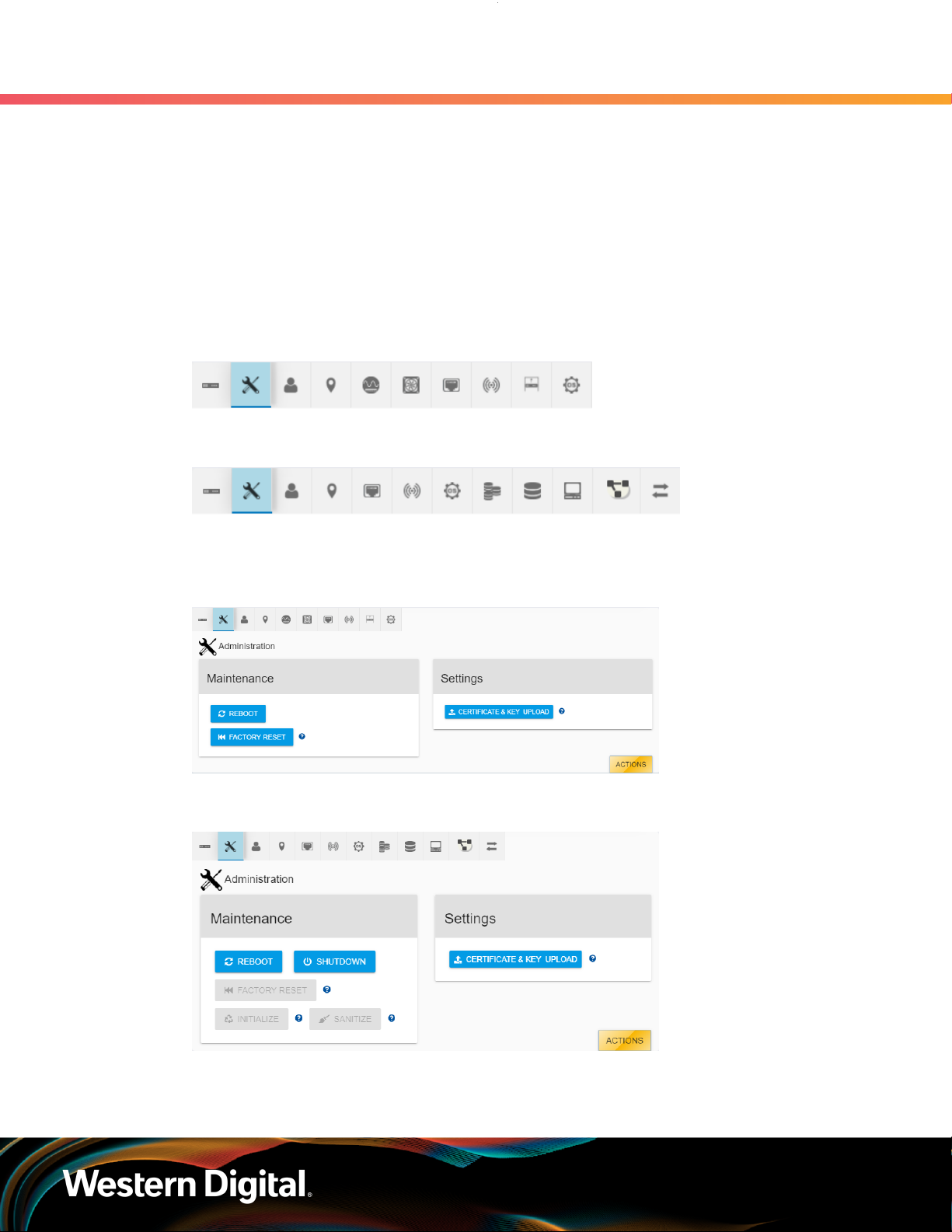
Step 2 : Click the device's Administration icon:
Navigate to the chassis or storage device (see Navigating to a Device (page 50)).
Figure 75: Chassis Device Administration Icon
Figure 76: Storage Device Administration Icon
The Administration information appears:
Figure 77: Chassis Device Administration Information
Figure 78: Storage Device Administration Information
Step 3 : Click the Certificate & Key Upload button:
57
Page 65

User Guide
3. Management
3.1 OCGUI
The TLS Certificate & Key Pair window appears, showing the Browse & Select Certificate &
Key Pair step:
Step 4 : Click the Select File button:
Step 5 : Navigate to the location of the appropriate PEM files for the Certificate File and Key File fields:
Note: The files are not validated. It is the user's responsibility to ensure that the
correct file is chosen for the appropriate field. If the chosen files are not valid,
the OCGUI will reuse the defaults already on the system.
58
Page 66

User Guide
3. Management
3.1 OCGUI
Step 6 : Click the Next button:
The TLS Certificate & Key Pair confirmation window updates, showing the Upload TLS
Certificate & Key Pair step:
59
Page 67

User Guide
3. Management
3.1 OCGUI
Step 7 : Confirm that the correct files are listed for Certificate and Key. If so, select the Please Confirm
checkbox and click the Upload Certificate & Key button:
The TLS Certificate & Key Pair confirmation window closes, and the device's dashboard
appears.
Step 8 : Click the Device Information icon:
60
Page 68

User Guide
3. Management
3.1 OCGUI
Figure 83: Chassis Device Information Icon
Figure 84: Storage Device Information Icon
The Device Information appears:
Figure 85: Chassis Device Information
61
Page 69

User Guide
3. Management
3.1 OCGUI
Figure 86: Storage Device Information
Step 9 : Click the Device Logs button:
The Device Log Viewer appears:
62
Page 70

User Guide
3. Management
3.1 OCGUI
Step 10 : Confirm that the chosen certificate file is one of the selectable options. If so, a secure HTTPS
connection has been established:
3.1.6.4 Creating Accounts
This task provides instructions for creating a user account on the OpenFlex F3x00 and E3000 using the
OCGUI.
63
Page 71

User Guide
Step 1 : Navigate to the chassis or storage device (see Navigating to a Device (page 50)).
Step 2 : Click the device's Accounts icon:
3. Management
3.1 OCGUI
Figure 89: Chassis Device Accounts Icon
Figure 90: Storage Device Accounts Icon
The Accounts information appears:
Figure 91: Chassis Device Accounts Information
Figure 92: Storage Device Accounts Information
Step 3 : Click the Create Accounts button:
The Create Accounts window appears, showing the Account Details step:
64
Page 72

User Guide
Step 4 : Type a User Id, choose a Role, and type a Password:
3. Management
3.1 OCGUI
Step 5 : Click the Create button to create the account:
Step 6 : Click Close to close the Create Accounts window:
The Accounts information appears, showing the newly created account:
65
Page 73

User Guide
3. Management
3.1 OCGUI
Figure 97: Chassis Device New Account
Figure 98: Storage Device New Account
3.1.6.5 Configuring a Location
This task includes instructions for configuring location information for the OpenFlex F3x00 and E3000
using the OCGUI.
Step 1 : Navigate to the chassis or storage device (see Navigating to a Device (page 50)).
Step 2 : Click the device's Location icon:
Figure 99: Chassis Device Location Icon
Figure 100: Storage Device Location Icon
The Location information appears:
66
Page 74

User Guide
3. Management
3.1 OCGUI
Step 3 :
Each location attribute can be assigned a value by clicking its pencil icon in the Value column.
Add the appropriate text to the field, and click the check mark to save the value. Enter all of
the values that apply.
3.1.6.6 Editing Port Information
This task provides instructions for editing the port information for the OpenFlex F3x00 and E3000 using
the OCGUI.
Step 1 :
Step 2 : Click the device's Ports icon:
Navigate to the chassis or storage device (see Navigating to a Device (page 50)).
Figure 102: Chassis Device Ports Icon
Figure 103: Storage Device Ports Icon
The Ports information appears:
67
Page 75

User Guide
3. Management
3.1 OCGUI
Figure 104: Chassis Device Ports Information
Figure 105: Storage Device Ports Information
Step 3 : To edit the port information for a device, click the pencil icon next to that port's Adapter
name.
The Update Port window appears, showing the Address Type, IP, MTUBytes step:
68
Page 76

User Guide
3. Management
3.1 OCGUI
Figure 106: Chassis Device Update Port Window
Figure 107: Storage Device Update Port Window
Step 4 : Edit the port information for the device and click the Next button:
The Confirmation step appears:
69
Page 77

User Guide
3. Management
3.1 OCGUI
Step 5 : Select the Please Confirm checkbox to confirm the edits:
Step 6 : Click the Update button to save the updates:
70
Page 78

User Guide
3.1.6.7 Setting up IPv6 on the Chassis Management Port
This task provides instructions for setting up IPv6 on the E3000 chassis device's management port using
the OCGUI.
3. Management
3.1 OCGUI
Note: IPv6 is only available on the E3000 management port; it is not available on the F3x00
storage device's data ports. The defalt networking setting for the E3000 is IPv4 DHCP. It can
be configured for IPv6 static or DHCP if desired. After a factory reset, the networking setting
will remain undefined until one of the available options is chosen.
Step 1 :
Step 2 : Click the chassis's Ports icon:
Step 3 : In the Identifier column, click the link that reads: <Click to Assign a Global IPv6 Address>:
Navigate to the chassis device (see Navigating to a Device (page 50)).
The Ports information appears:
The Update Port window appears, showing the Address Type, IP, MTUBytes step:
71
Page 79

User Guide
3. Management
3.1 OCGUI
Step 4 : From the drop-down list, select the DHCPv6 option:
Step 5 : Click the Next button:
The Confirmation step appears:
72
Page 80

User Guide
3. Management
3.1 OCGUI
Step 6 : Select the Please Confirm checkbox to confirm the selection:
Step 7 : Click the Update button to save the update:
A modal appears for a brief moment, showing the progress of the IPv6 configuration.
Step 8 : When the Ports information appears again, review the Network Type column for the edited
port to ensure that IPv6 is now configured:
73
Page 81

User Guide
3.1.6.8 Checking Sensors
This task provides instructions for checking the sensors of the OpenFlex F3x00 and E3000 using the
OCGUI.
Step 1 : Navigate to the chassis or storage device (see Navigating to a Device (page 50)).
Step 2 : Click the device's Sensors icon:
3. Management
3.1 OCGUI
Figure 114: Chassis Device Sensors Icon
Figure 115: Storage Device Sensors Icon
The Sensors information appears:
74
Page 82

User Guide
3. Management
3.1 OCGUI
Figure 116: Chassis Device Sensors Information
Figure 117: Storage Device Sensors Information
Step 3 :
The sensor section provides an Identifier or name for each sensor, its Type, and Current
Reading. The chassis's sensor information also includes a Health status. Hovering over the
information icon in the temperature column will provide specific information related to that
component's temperature thresholds, if applicable.
3.1.6.9 Checking the OS
This task provides instructions for checking the operating system of the OpenFlex F3x00 and E3000
using the OCGUI.
Step 1 :
Step 2 : Click the device's OS icon:
Navigate to the chassis or storage device (see Navigating to a Device (page 50)).
75
Page 83

User Guide
3. Management
3.1 OCGUI
Figure 118: Chassis Device OS Icon
Figure 119: Storage Device OS Icon
The Device OS information appears:
Figure 120: Chassis Device OS Information
Figure 121: Storage Device OS Information
Step 3 :
Review the operating system information for the device. If the OS requires updating, see
Upgrading Firmware (page 106).
3.1.6.10 Checking Pools
This task provides instructions for checking the pools of an F3x00 storage device using the OCGUI.
Step 1 :
Step 2 : Click the storage device's Pools icon:
Navigate to the storage device (see Navigating to a Device (page 50)).
The Pools information appears:
76
Page 84

User Guide
Step 3 : The information list provides an Identifier for each pool, its Remaining Capacity, Health, and
3. Management
3.1 OCGUI
Predicted Life Left Percent. Hovering over the information icon in the Remaining Capacity
column will provide details about the pool's remaining capacity.
3.1.6.11 Checking and Creating Volumes
This task provides instructions for checking and creating volumes on an F3x00 storage device using the
OCGUI.
Step 1 :
Step 2 : Click the storage device's Volumes icon:
Navigate to the storage device (see Navigating to a Device (page 50)).
The Volumes information appears:
77
Page 85

User Guide
3. Management
3.1 OCGUI
Step 3 :
Step 4 : Click the Create Volumes button:
Review the listed volumes on the storage device.
The Create Volumes window appears, showing the Pool & Capacity step:
Step 5 : Select a Pool from the drop-down list, and use the Capacity slider to assign a capacity to the
volume being created. If multiple volumes of the same capacity are needed, select the number
of volumes from the Number of Volumes drop-down list:
78
Page 86

User Guide
3. Management
3.1 OCGUI
Step 6 : Click the Next button to continue:
The Names & Description step appears:
Step 7 : Type a name in the Volume Name field. The remaining fields for Description, NQN, and Allow
Any Host are optional:
79
Page 87

User Guide
3. Management
3.1 OCGUI
Step 8 : Click the Next button to continue:
The Confirmation step appears:
Step 9 : Review the volume entries and edit or update each as needed. Then check the Please Confirm
checkbox:
80
Page 88

User Guide
3. Management
3.1 OCGUI
Step 10 : Click the Create button to create the new volume(s):
The Creation step appears, showing creation progress and providing confirmation when the
volume creation is complete:
81
Page 89

User Guide
Step 11 : Click Close and review the Volumes information to verify that the newly created volume(s)
3. Management
3.1 OCGUI
appears on the list.
3.1.6.12 Extending Volumes
This task provides instructions for extending (increasing) the capacity of an existing volume within an
F3x00 storage device using the OCGUI.
Before you begin:
Note: A volume may only be extended a maximum of seven (7) times during its life. If that
volume is deleted and another recreated in its place, the new volume can then be extended
up to the maximum of seven (7) times.
Step 1 :
Step 2 : Click the storage device's Volumes icon:
Navigate to the storage device (see Navigating to a Device (page 50)).
The Volumes information appears:
82
Page 90

User Guide
Step 3 : Click the pencil icon in the Capacity column of the volume to be extended:
3. Management
3.1 OCGUI
The Extend Volume Capacity window appears:
83
Page 91

User Guide
3. Management
3.1 OCGUI
Step 4 :
Step 5 : Click the Update button to complete the capacity extension for the volume:
Step 6 :
To extend (increase) the capacity of the volume, click and drag the capacity slider to the right,
or type the capacity increase into the text field on the right.
A progress modal appears for a brief moment.
When the Volumes information is visible again, check the Capacity column and verify that the
capacity of the volume has been increased.
3.1.6.13 Configuring a Host
This task provides instructions for configuring a host on an F3x00 storage device using the OCGUI.
Step 1 :
Step 2 : Click the storage device's Hosts icon:
Navigate to the storage device (see Navigating to a Device (page 50)).
The Hosts information appears:
Step 3 : Click the Create Hosts button:
84
Page 92

User Guide
3. Management
3.1 OCGUI
The Create Hosts window appears, showing the Name & Description step:
Step 4 : Type a Host Name and Description for the host.
Step 5 : Click the Next button:
The Create Hosts window updates, showing the Confirmation step:
85
Page 93

User Guide
3. Management
3.1 OCGUI
Step 6 : Click the checkbox next to Please Confirm, and then click the Create button:
The newly created host will appear in the list on the storage device's Hosts page.
3.1.6.14 Checking and Creating VLANs
This task provides instructions for checking and creating VLANs on an F3x00 storage device using the
OCGUI.
Step 1 :
Step 2 : Click the storage device's VLANs icon:
Navigate to the storage device (see Navigating to a Device (page 50)).
The VLANs information appears:
86
Page 94

User Guide
Step 3 : Review the listed VLANs for the storage device.
Step 4 : Click the Create VLANS button:
3. Management
3.1 OCGUI
The Create VLANs window appears, showing the Ports, Tags & Increments step:
Step 5 : Select the checkbox beside the applicable port to create a VLAN on that port. Use the Tag
field to define an identifier (any number between 2 and 4094) that will be used for segregating
the VLAN's traffic:
87
Page 95

User Guide
3. Management
3.1 OCGUI
Step 6 : Click the Next button:
The Confirmation step appears:
Step 7 : Review the VLAN(s) selections and edit each as necessary. The IP Address field is required;
enter a valid IPv4 address and CIDR that does not conflict with an existing IP address. Then
check the Please Confirm checkbox:
88
Page 96

User Guide
3. Management
3.1 OCGUI
Step 8 : Click the Create button:
A modal appears for a brief moment to show the VLAN creation progress.
Step 9 : When the VLANs information is visible again, check the list to ensure that the created VLAN(s)
is included.
3.1.6.15 Configuring a Path to a Host
This task provides instructions for configuring a path between a volume and a host on an F3x00 storage
device using the OCGUI.
Before you begin:
89
Page 97

User Guide
3. Management
3.1 OCGUI
Note: A path is a dedicated channel of communication, which cannot be established until
both the volume and host have been created.
Note: The following instructions define how to create a path to a host through the storage
device's Volumes section. That same path may also be created from the other direction—to
a volume through the storage device's Hosts page.
Step 1 :
Step 2 : Click the storage device's Volumes icon:
Navigate to the storage device (see Navigating to a Device (page 50)).
The Volumes information appears:
Step 3 : From the list of available volumes, identify the one that will be used to create the path.
If that volume has been configured to allow any host, a dedicated path cannot be established
between it and a specific host. If this is the case, it will be indicated by the following:
The Allow Any Host setting will be toggled to the ON (enabled) position:
•
• When the user hovers over the path arrows beside the volume Name, the tooltip will
indicate that this volume is expecting a VLAN path, not a host path:
90
Page 98

User Guide
Step 4 : If needed, disable the Allow Any Host setting for that volume by clicking the on/off toggle
Step 5 : Click the path arrows beside the volume Name.
3. Management
3.1 OCGUI
switch:
When the user hovers over the path arrows beside the volume Name, the tooltip will indicate
that this volume is now expecting a host path:
The Create Paths to Hosts dialog box opens, showing the Hosts Selection step:
Step 6 : From the Select Hosts drop-down list, select one or more hosts to be connected to this
volume. Then click the Next button:
The Confirmation step appears, displaying the chosen host(s):
91
Page 99

User Guide
3. Management
3.1 OCGUI
Step 7 : Select the checkbox beside Please Confirm, and then click the Map Hosts button:
A dedicated path between the selected volume and hosts(s) is created.
Step 8 : To verify that the path was created, click the storage device's Paths icon:
The Paths information appears:
92
Page 100

User Guide
Step 9 : Review the listed paths to identify the one referencing the previously selected volume and
3.1.6.16 Configuring a Path to a VLAN
This task provides instructions for configuring a path between a volume and a VLAN on an F3x00 storage
device using the OCGUI.
Before you begin:
3. Management
3.1 OCGUI
host(s); the volume and host NQNs will be listed under the Volume NQN and Host NQN
columns.
Note: A path is a dedicated line of communication, which cannot be established until both
the volume and VLAN have been created.
Note: The following instructions define how to create a path to a VLAN through the storage
device's Volumes page. That same path may also be created from the other direction—to a
volume through the device's VLANs page.
Step 1 :
Step 2 : Click the storage device's Volumes icon:
Navigate to the storage device (see Navigating to a Device (page 50)).
The Volumes information appears:
Step 3 : From the list of available volumes, identify the one that will be used to create the path.
The volume must be configured to allow any host, or a path cannot be established between
it and a VLAN. If the volume is incorrectly configured, it will be indicated by the following:
The Allow Any Host setting will be toggled to the OFF (disabled) position:
•
93
 Loading...