

Page 1

T
echnical
Reference
Manual
Ultrastar® DC HA210
(Previously known as Ultrastar 7K2)
Capacity Enterprise HDD
HUS722T2TALA604
HUS722T1TALA604
Page 2

Revision 1.1 (28 July 2016)
Revision 1.2 (01 May 2018)
One MB is equal to one million bytes, one GB is equal to one billion bytes and one TB equals 1,000GB (one trillion
bytes) when referring to storage capacity. Accessible capacity will vary from the stated capacity due to formatting and
partitioning of the drive, the computer’s operating system, and other factors.
The following paragraph does not apply to any jurisdiction where such provisions are inconsistent with local law: THIS
PUBLICATION IS PROVIDED "A S IS" WI TH O UT WAR RA NT Y OF A N Y KIN D, EI T HE R EX PR ESS O R IMP L IE D,
INCLUDING, BUT NOT LIMITED TO , T HE IMPLIED W ARRA NTIES OF MERCHANTABILITY OR FITNESS FOR A
PARTIC ULA R PU R PO SE.
This publication could include technical inaccuracies or typographical errors. Changes are periodically made to the
information herein; these changes will be incorporated in new editions of the publication. There may be improvements or
changes in any products or programs described in this publication at any time. It is possible that this publication may
contain reference to, or information about, Western Digital products (machines and programs), programming, or services
that are not announced in your country. Such references or information must not be construed to mean that Western
Digital Corporation intends to announce such Western Digital products, programming, or services in your country.
Technical information about this product is available by contacting your local Western Digital product representative or
on the Internet at: support@wdc.com
.
Western Digital Corporation may have patents or pending patent applications covering subject matter in this document.
The furnishing of this document does not give you any license to these patents.
© 2018 Western Digital Corporation or its affiliates.
Ultrastar, RAFF, Data Lifeguard, the Western Digital logo and Ultrastar are registered trademarks or trademarks of
Western Digital Corporation or its affiliates in the U.S. and/or other countries. Other trademarks are the property of
their respective owners.
References in this publication to Western Digital-branded products, programs, or services do not imply that they will be
made available in all countries. Product specifications provided are sample specifications and do not constitute a
warranty. Actual specifications for unique part numbers may vary. Please visit the Support section of our website,
support@wdc.com
, for additional information on product specifications. Pictures shown may vary from actual products.
Page 3
Ultrastar® DC HA210
Technical Reference Manual
Page 4
Ultrastar DC HA210
TABLE OF CONTENTS
1.0 DESCRIPTION AND FEATURES ................................................................................................................................... 7
1.1 General Description ........................................................................................................ 7
1.2 Product Features ............................................................................................................. 7
2.0 SPECIFICATION ................................................................................................................................................................ 9
2.1 Performance Specifications ............................................................................................. 9
2.2 CacheFlow™ ................................................................................................................. 10
Write Cache ............................................................................................................ 10
Read Cache ............................................................................................................ 10
2.3 Mechanical Specifications ............................................................................................. 11
Physical Dimensions ............................................................................................... 12
Drive Mounting ...................................................................................................... 12
2.4 Electrical Specification s ................................................................................................. 13
Mean Current Requirements and Power Dissipation ................................................. 13
Power Savings Modes ............................................................................................. 13
Input Voltage Requirements .................................................................................... 15
Ripple .................................................................................................................... 15
Power Connectors and Cables ................................................................................. 15
2.5 Environmental Specifications......................................................................................... 16
Shock and Vibration ................................................................................................ 16
Temperature and Humidity ..................................................................................... 17
Temperature Measurement ..................................................................................... 17
Cooling .................................................................................................................. 18
Atmospheric Pressure ............................................................................................. 18
Acoustics ............................................................................................................... 18
RoHS (Restriction of Hazardous Substances) ............................................................ 18
2.6 Agency A pprovals ......................................................................................................... 19
2.7 Full Model Number Specification ................................................................................... 19
3.0 PRODUCT FEATURES .................................................................................................................................................. 20
3.1 SATA 6 Gb/s ................................................................................................................. 21
3.2 Time-Limited Error Recovery (TLER) ............................................................................... 21
3.3 Rotary Acceleration Feed Forward (RAFF)™ ..................................................................... 22
3.4 Perpendicular Magnetic Recording (PMR) ........................................................................ 23
3.5 IntelliSeek ..................................................................................................................... 23
3.6 Native Comma nd Q ue uing (NCQ) ................................................................................... 23
3.7 Pre-emptive Wear Leveling (PWL) ................................................................................... 23
3.8 MicroFemto Slider ......................................................................................................... 23
3.9 S.M.A.R.T. Command Transport (SCT) ............................................................................ 24
Write Same ............................................................................................................. 24
Temperature Reporting ........................................................................................... 24
3.10 World Wide Name (WWN) ............................................................................................... 24
3.11 Power Loss Data Protection ........................................................................................... 24
3.12 Hot Plug Support .......................................................................................................... 25
3.13 Active LED Status .......................................................................................................... 25
3.14 Fluid Dynamic Bearings (FDB) ........................................................................................ 25
3.15 Staggered Spinup and Activity Indication (SATA Power Pin
Staggered Spinup ................................................................................................... 25
Activity Indication ................................................................................................... 25
3.16 48-bit Logical Block Addressing (LBA) ............................................................................ 26
3.17
Self-Monitoring, Analysis, and Reporting Technology
3.18 Password Security Mode ................................................................................................ 27
Master and User Passwords ..................................................................................... 27
Security Levels ........................................................................................................ 27
3.19 Data Path Protection (DPP) ............................................................................................. 27
3.20 Manufacturing Option Block .......................................................................................... 27
11) .............................................. 25
(S.M.A.R.T.) ....................................... 26
Hard Disk Drive
Technical Reference Manual
4
Page 5
Ultrastar DC HA210
RELIABILITY .................................................................................................................................................................... 28
4.0
4.1 Reliability Considerations .............................................................................................. 28
4.2 Error Rates.................................................................................................................... 28
Error Rates ............................................................................................................. 28
Environmental Interference ..................................................................................... 29
4.3 Reliability Features Set .................................................................................................. 30
Data Lifeguard™* .................................................................................................... 30
Thermal Management ............................................................................................. 30
Internal Environmental Protection System ................................................................ 30
Defect Management ................................................................................................ 30
Recoverable Errors .................................................................................................. 30
Unrecoverable Errors .............................................................................................. 30
Automatic Defect Retirement .................................................................................. 31
Error Recovery Process ............................................................................................ 31
5.0 ATA COMMAND SET .................................................................................................................................................... 32
5.1 Host Interface Commands ............................................................................................. 32
ATA-7/ATA-8 Commands ...................................................................................... 32
SATA Commands .................................................................................................... 33
Obsolete Commands .............................................................................................. 33
SCT Commands ...................................................................................................... 34
5.2 S.M.A.R.T. (B0h) ............................................................................................................ 35
Read Attribute Values Sub-Command ...................................................................... 35
Supported Attributes .............................................................................................. 36
Read Log Sector ...................................................................................................... 37
5.3 Identify Device (ECh) ..................................................................................................... 38
5.4 Set Features (EFh) ......................................................................................................... 44
6.0 DRIVE HANDLING AND MAINTENANCE .............................................................................................................. 45
6.1 Unpacking .................................................................................................................... 45
Handling Precautions .............................................................................................. 45
Inspection of Shipping Container ............................................................................. 45
Removal From Shipping Container ........................................................................... 45
Removal From Static Shielding Bag .......................................................................... 46
Moving Precautions ................................................................................................ 46
6.2 Hard Drive Installation .................................................................................................. 46
Backplane Usage
..................................................................................................... 47
6.3 Maintenance ................................................................................................................. 48
7.0 GLOSSAR Y ....................................................................................................................................................................... 49
Hard Disk Drive
Technical Reference Manual
5
Page 6

Ultrastar DC HA210
LIST OF FIGURES
Figure 1 Mounting Dimensions ............................................................................................... 11
Figure 2 Drive Base Casting Thermoco upl e Location ............................................................... 17
Figure 3 Forced Airflow Directio n ........................................................................................... 18
Figure 4 Dual Linear Sensor Rotational Acce leration Feed Forward (RAFF) ................................ 22
Figure 5 Manuf act ur ing Option Block ...................................................................................... 27
Figure 6 SATA Cable Connections ........................................................................................... 46
Figure 7 Connector Pair Blind Mate Misalignment Allowable .................................................... 47
Figure 8 Device Backplane Connection .................................................................................... 47
LIST OF TABLES
Table 1 Physical Specifications .................................................................................................. 9
Table 2 Performance Specifications .......................................................................................... 9
Table 3 Device/Head Register ................................................................................................ 16
Table 4 Maximum and Reliability Operating Temperature Limits (Drive Baseplate) ................... 17
Table 5 Full Model Number Description .................................................................................. 19
Table 6 ATA-7/ATA-8 Command Opcodes .............................................................................. 32
Table 7 Optional Subcommands ............................................................................................. 33
Table 8 Obsolete Command Opcodes ..................................................................................... 33
Table 9 SCT Action Codes ....................................................................................................... 34
Table 10 Definitions for the 512 Bytes. ................................................................................... 35
Table 11 Supported Attributes ................................................................................................ 36
Table 12 Log Address Definition ............................................................................................ 37
Table 13 Identify Device Command ......................................................................................... 38
Hard Disk Drive
Technical Reference Manual
6
Page 7

Ultrastar DC HA210
DESCRIPTION AND FEATURES
General Description
Western Digital Ultrastar Capac ity Enterprise hard drives offer up to 10 TB capacities and are available
with SATA interface. With the highest error tolerance and MTBF of any capacity-optimized drive,
Western Digital Ultrastar deliver s the durability and reliability required in tightly packed vibration prone
multi-drive systems. The combination of high-capacity, peak performance and robust design make
Western Digital Ultrastar drives ideal for heavy workload environments, cloud storage, RAID arrays,
external storage arrays, data warehousing, and mining applications.
Product Features
Serial ATA (SATA) — Serial ATA (SATA) is the next generation bus interface for hard drives. It is
designed to replace Parallel ATA, and has many advantages including increased transfer rate,
improved signal integrity, enhanced data protection, and hot plug support.
Time-Limited Error Recovery (TLER) — TLER prevents hard drive error recovery fallout by
limiting the time the drive spends in error recovery, providing increased performance, improved
availability, and lower total cost of ownership in RAID arrays.
Rotary Acceleration Feed Forward (RAFF) — These drives employ RAFF technology to maintain
hard drive performance in high vibration environment s through adap t ive compensat i on of the servo
system.
Perpendicular Magnetic Recording (PMR) — With PMR technology the magnetization of each
data bit is aligned vertically to the sp inning disk, ra ther than longitudinally as has been the case in
hard drive technology for decades. This enables more data on a given disk than is possible with
conventiona l longitudinal recording, a nd provides a p l atform for futur e expansion of hard drive
densities.
IntelliSeek™ — Key product feature that calculates optimum seek speeds to lower power
consumption, noise, and vibration.
Native Command Queuing (NCQ) — Performance of a random I/O workload can be improved
through intelligent re-ordering of the I/O requests so they read/write to and from the nearest available
sectors and minimize the need for additional disk revolutions or head actuator movement. This
improvement can be achieved though Native Command Queing (NCQ) , which is supp orted by these
hard drives .
Pre-emptive Wear Leveling (PWL) — This feature provides a solution for protecting the recording
media against mechanical wear. In cases where the drive is so busy with incoming commands that it
is forced to stay in a same cylinder position for a long time, the PWL control engine initiates forced
seeks so that disk lubricant maintains an even distribution and does not become depleted. This feature
ensures reliability for applications that perform a high incidence of read/write operations at the same
physical location on the disk.
MicroFemto Slider — These drives incorporate the next generation of femto slider form factor in
which the read/write head is mounted o n the small, lightweight microfemto slider that all ows the head
to move more quickly from track to track on the disk.
S.M.A.R.T. Command Transport (SCT) — The SCT Command Transport feature set provides a
method for a host to send commands and data to a device and for a device to send data and status to a
host using log pages.
World Wide Name (WWN) — The World Wide Name (WWN) defined in ATA/ATAPI-7 is a
modification of the IEEE extended unique identifier 64 bit standard (EUI-64) and is comprised of three
major components: naming authority, organizationally unique id e ntifie r (OUI) and serial number.
This product’s OUI is 0014EEh.
Hard Disk Drive
Technical Reference Manual
7
Page 8

Ultrastar DC HA210
Reliability Features Set-Data Lifeguard™ — Representing the ongoing commitment to data
Power Loss Data Protection — Upon power loss, the drive utilizes stored spindle energy to back
Hot Plug Support — SATA supports hot plugging (also known as “hot swapping”), the ability to
Active LED Status — The drive supports external LED requirements. It provides an activity LED
Fluid Dynamic Bearings (FDB) — Bearing design that incorporates a layer of high-viscosity
Staggered Spin-Up — Next generation SATA 6 Gb/s feature that allows the system to control
CacheFlow™ —This unique , mu lt i -ge neration caching algorith m evaluates the way data is read from
48-bit Logical Block Addressing (LBA) — Western Digital SATA drives support both 48-bit and 28-
Power Management — The drive supports the ATA and SATA power management command set,
Self-Monitoring, Analysis, and Reporting Technology (S.M.A.R.T.) — S.M.A.R.T. enables a
ATA Security — The drive supports the ATA Security Mode Feature set. The ATA Security Mode
Data Path Protection (DPP) — A feature that prevents possible electronic failures from corrupting
protection, Data Lifeguard includes features that enhance the drive’s ability to prevent data loss.
Data Lifeguard data protection utilities include thermal management, an environ mental protection
system, and embedded error detection and repair features that automatically detect, isolate, and
repair problem areas that may develop over the extended use of the hard drive. With these enhanced
data reliability features, the drive can perform more accurate monitoring, error repair, and deliver
exceptional data security.
up the HDD cache to on- board flash. This allows deeper write queues which boosts performance,
while minimizing data loss/corruption such as write splices that can occur during unexpected
power losses.
swap out a failed hard drive without having to power down the s ystem or reboot. This capability
contributes to both data availability and serviceability without any associated downtime, making it a
critical feature for extending SATA into enterprise applications.
output which is ON during c ommand execution and OFF otherwise.
lubricant instead of ball bearings in the hard drive spindle motor. As an alternative to conventional ball
bearing technology, FDB designs provide increased non-operational shock resistance, speed control,
and improved acoustics.
whether the drive will spin up immediately or wait until the interface is fully ready.
and written to the drive and adapts “on-the-fly” to the optimum read and write caching method s.
CacheFlow minimizes disk seek operations and overheads due to rotational latency. CacheFlow
supports sequential and random write cache. With write cache and other CacheFlow features, the user
can cache both read and write data. The cache can hold multiple writes and collectively write them to
the hard disk.
bit LBA and CHS-based addressing. LBA is included in advanced BIOS and operating system device
drivers and ensures high capacity disk integration.
allowing the host to reduce the power consumption of the drive by issuing a variety of power
management commands.
drive’s internal status to be monitored through diagnostic commands at the host level and during
offline activities. S.M.A.R.T. devices employ data analysis algorithms that are used to predict the
likelihood of some near-term degradation or fault conditions. When used with a S.M.A.R.T.
application, the drive can alert the host system of a negative reliability status condition. The host
system can then warn the user of the impend ing risk of data loss and recommend an appropriate
action.
feature set allows the user to create a device lock password that prevents unauthorized hard disk
access even if the drive is removed from the host computer. The correct password must be supplied to
the hard drive in order to access user data. Both the User and Master Password features are supported,
along with the High and Maximum security modes. The Master Password Revision code is also
supported. This feature varies by drive co nfiguration and may not be avail able on all co nfigurations.
data on the hard drive.
Hard Disk Drive
Technical Reference Manual
8
Page 9
Ultrastar DC HA210
Capacity
2 TB
1 TB
Host Bytes Per Sector
512
512
Channel Recording Method
LDPC–Low Density Parity Code
Average Seek (without overhead)
SPECIFICATION
Table 1 Physical Specifications
Physical Specifications
Interface SATA 6 Gb/s SATA 6 Gb/s
Physical Bytes Per Sector 512 512
User Sectors per Drive 3,907,029,168 1,953,525,168
Servo Type Embedded Embedded
1
As used for storage capacity, one megabyte (MB) = one million bytes, one gigabyte (GB) = one billion bytes,
and one terabyte (TB) = one trillion bytes. Total accessible capacity varies depending on operating
environment. As used for buffer or cache, one megabyte (MB) = 1,048,576 bytes. As used for transfer rate
or interface, megabyte per second (MB/s) = one million bytes per second, and gigabit per second (Gb/s) =
one billion bits per second. Effective maximum SATA 6 Gb/s transfer rate calculated according to the Serial
ATA specification published by the SATA-IO organization as of the date of this document. Visit www.sataio.org for details.
Performance Specifications
1
HUS722T2TALA604
HUS722T1TALA604
Table 2 Performance Specifications
- Read
- Write
Average Latency 4.2 ms (nominal)
Rotational Speed 7200 RPM (nominal)
Data Transfer Rate (maximum at OD)
- Maximum burst interface transfer rate
- Maximum sustained interface transfer rate
Buffer Size 128 MB
Spindle Start Time
- From Power-on to Drive Ready
Spindle Stop Time <10s average
Load/Unload Cycles
1
As used for transfer rate or interface, megabyte per second (MB/s) = one million bytes per second, and gigabit per
second (Gb/s) = one billion bits per second. Effective maximum SATA 6 Gb/s transfer rate calculated according to the
Serial ATA specification published by the SATA-IO organization as of the date of this document. Visit www.sata-io.org
for details.
2
Defined as the time from power-on to the setting of Drive Ready and Seek Complete including calibration.
Controlled unload at ambient condition.
3
1
2
7.7 ms average
8.3 ms average
6 Gb/s
HUS722T2TALA604: 200 MB/s
HUS722T1TALA604: 184 MB/s
15s average (FAST spinup mode)
18s average (STANDARD spinup mode)
600,000 minimum
Hard Disk Drive
Technical Reference Manual
9
Page 10

Ultrastar DC HA210
CacheFlow™
CacheFlow is the unique, multi-generation disk caching system. It incorporates read cache with write
cache.
CacheFlow was designed to obtain maximum performance with today’s most popular operating s yste ms
and applications. CacheFlow increases performance over prior caching algorithms by increasing the
number of times that requested data is in the cache. This reduces the number of host commands that
require actual media access thereby improving overall drive performance.
Typical applications perform a variety of access patterns, such as random, sequential, and repetitive.
CacheFlow is designed to dynamically adapt to the changes in access patterns that occur during the course
of application execution.
Random mode is the default operational mode for CacheFlow. Once CacheFlow detects a sequential access
pattern, it leaves random mode. CacheFlow also performs predictive read operations to increase the
probability that data requested in fut ure c ommands already exists in the cache.
CacheFlow partitions the buff e r into multiple segments to allow for the fact that applica tions may access
multiple non-contiguous areas on the disk. CacheFlow tracks the amount of valid data in each segment
and controls the deallocation of segments to maximize drive performance.
Write Cache
CacheFlow is designed to improve both single and multi-sector write performance by reducing delays
caused by seek time and rotational latency.
The write cache adaptively detects random and sequential access patterns during application execution.
If a defective sector is found during a write cache operation, that sector is automatically relocated before the
write occurs.
Read Cache
CacheFlow implements a multiple segment read cache. Cache segments are assigned to read commands as
they are received from the host.
Each read segment consists of pre and post read sectors in addition to the host-requested sectors. This
maximizes the amount of cache data in the drive’s buffer, thereby increasing the likelihood of cache hits and
improving o verall performance.
Hard Disk Drive
Technical Reference Manual
10
Page 11
Ultrastar DC HA210
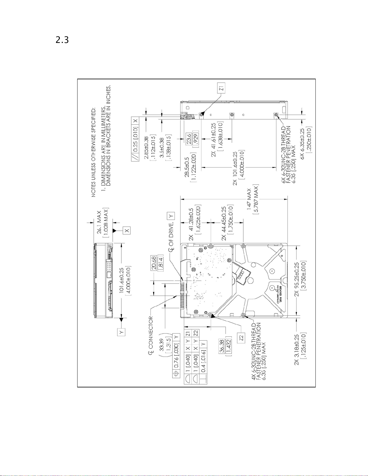
Mechanical Specifications
Figure 1 shows the mounting dimensions and locations of the screw holes for the drive.
Figure 1 Mounting Dimensions
Hard Disk Drive
Technical Reference Manual
11
Page 12
Ultrastar DC HA210
English
Metric
Dimension
Tolerance
Dimension
Tolerance
Height
1.028 inches
MAX
26.1 mm
MAX
Length
5.787 inches
MAX
147.0 mm
MAX
Width
4.00 inches
±0.01 inch
101.6 mm
±0.25 mm
Weight
1.41 pounds
±10%
0.64 kg
±10%
Use either the four bottom screws or at least four of the side mounting screws to rigidly suppo rt the drive
and prevent vibration. Some adaptor frames may not have the mechanical design structure capable of
mounting the drive to meet the specified shock and vibration requirements.
The hard drive itself does not pr ovide electrical isolation between mounting locations and drive ground
connection. If electrical isolation is required, the system designer or integrator would be responsible for
providing a s olution.
If your system does not support hot pl ugg in g (se e “ Hot Plug Support on page.25), it must be turned off and
unplugged before installing your hard drive.
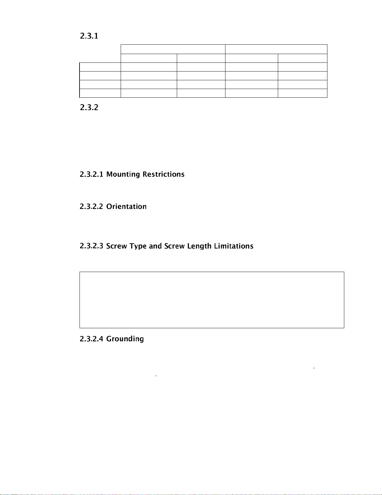
Physical Dimensions
Drive Mounting
You can mou nt the hard drive in the X, Y, or Z axis, depending upon the physi cal design of your system.
For best results, mount the drive with all four screws grounded to the cha s s is. If all four screws are not
used, see "Grounding" on page.12.
The hard drive should be mounted to the chassis using four 6-32 screws. Recommended screw torque is 5
in-lb. Maximum screw torque is 10 in-lb.
CAUTION: Screws that are too long can damage the hard drive. Hard drive screw penetration
can differ between products depending upon hard drive design. Western Ditigal’s minimum
design criteria is to always meet the SFF 8301 industry standard specification. The industry
standard as defined in the SFF 8301 specifies a maximum of 3 mm screw penetration, and for a
minimum of 2.4 mm of thread engagement from both the screw and the hard drive.
See Figure 1
for allowable fastener penetration for this product family.
The PCBA and HDA grounds are always connected together in the drive and cannot be disconnected. The
drive mounting screws, unless intentionally isolated, will provide additional ground connections between
the HDA and the system chassis. If the drive isn't grounded via mounting screws as described
Drive Installation” on Page.46, there may be increased electrical emissions (EMI).
under “Hard
Hard Disk Drive
Technical Reference Manual
12
Page 13

Ultrastar DC HA210
1710 mA (max)
520 mA (peak)
Spinup Fast
2385 mA (max)
550 mA (peak)
Spinup Green
1190 mA (max)
505 mA (peak)
Operational Peak Current
1545 mA (peak)
870 mA (peak)
Sequential Read
315 mA
720 mA
7.4W
Sequential Write
315 mA
730 mA
7.4W
Random Read/Write
485 mA
455 mA
8.1W
Idle
315 mA
430 mA
5.9W
Idle_A
310 mA
290 mA
5.2W
Idle_B
295 mA
290 mA
5.0W
Idle C
110 mA
290 mA
2.8W
Standby Y
110 mA
290 mA
2.8W
Standby_Z
10 mA
285 mA
1.5W
Electrical Specifications
Mean Current Requirements and Power Dissipation
Operating Mode
Spinup Standard
1
When running at 3 Gb/s or as a single ported device, power will be lower t han the value listed. 2 All
peak and mean values are typical (measured at 25°C) except where specified as maximum.
spinup mode when not otherwise overridden.
3
Mean Current
12 VDC
735 mA
1350 mA
510 mA
1600 mA (max)
1, 2
5 VDC
295 mA
295 mA
295 mA
860 mA (max)
Mean Power
-
-
-
-
1, 2
3
Default
Mode
Mean Current
12 VDC
2
Mean Current
5 VDC
Mean Power
DIPM Off
2
2
1
When running at 3 Gb/s or as a single ported device, power will be lower than the value listed.
2
All peak and mean values are typical (measured at 25°C) except where specified as maximum.
Power Savings Modes
This product is capable of supporting both legacy ATA Advanced Power Management (APM) mode and
the new more extensive Extended Power Conditions (EPC) standards. Unless otherwise specified, the
default disk drive is shipped with the EPC mode enabled, and the legacy APM modes can be enabled via
the Set Feature command (Feature ‘4A’h, Sub Command ‘04’h). These two power savings
implementations are exclusively used, and thus not simultaneously supported.
This drive supports the legacy ATA power management commands that lower the average power
consumption of the hard drives. For example, to take advantage of the lower power consumption modes
of the drive, an energy efficient host system could implement a power management scheme that issues a
Standby Immediate command when a host resident disk inactivity timer expires. The Standby Immediate
command causes the drive to spin down and enter a low-power mode. Subsequent disk access commands
would cause the drive to spi n up and execute the new command. To avoid excessive wear on the drive due
to the starting and stopping of the HDA, set the host’s disk inactivity timer to no shorter than ten minutes.
Hard Disk Drive
Technical Reference Manual
13
Page 14

Ultrastar DC HA210
Western Digital drives additionally support T13 Extended Power Conditions, as stated in the ACS-2
specification. Power savings features, normally only available in notebook drives, are now included in our
Enterprise products. With these features enabled, drive power can be reduced automatically via inactivity
timer, or manually via Host command. In timer based mode, the drive automatically starts reducing its
power based on inactivity of co mma nd s from the Host. With progression into the idle states, the drive
saves more and more power, but consequently takes longer to recover and respond to Host media
commands.
A summary of the new low power modes and what the drive does in each mode is shown below:
Idle_A
Heads Floating Over Disk
<10 ms recovery
Idle_B
Heads Parked
<650 ms recovery
Idle_C
Heads Parked, Reduced RPM
3-15 sec recovery (see the Power Conditions Log for the drives actual recovery time)
Idle_c recovery current limited to the maximum user mode power.
Standby_Y
Heads Parked, Reduced RPM
3-15 sec recovery (see the Power Conditions Log for the drives actual recovery time)
Standby_y recovery can use full spin up power.
Standby_Z
Traditional standby
Drive not spinning
Recovery is similar to a typical TTR (Time To Ready) for the HDD
Western Digital has added the Power Condition Log, which defines the support, enable bits, and timers
for all power conditions. The power management timers start running after a ll Host commanded drive
activity is complete, and will run during drive background operations, but do not take effect until those
background operations are completed. The timer expiration min/max values are visible to the Host/
Initiator, but are rounded silently by the drive to its internal min/max values. The timer enable and timer
values can be marked independently as changeable. Please note that some Host Operating Systems may
be unable to take advantage of the inactivity timers, as they constantly access the Drive with writes to
update a time stamp. In these situatio ns it is advisable to extend the Idle_B ti mer value beyond the time
interval of the writes, or to disab le the timer entirely. Please see your Western Digital representative for
help with questions about these features .
Hard Disk Drive
Technical Reference Manual
14
Page 15
Ultrastar DC HA210
The input vol tage requirements are +5.0V ± 5% and +12.0V ± 10%.
Input Voltage Requirements
Ripple
+ 12 VDC
Maximum Frequency 200 mV (double amplitude) 0-30 MHz 100 mV (double amplitude) 0-30 MHz
+5 VDC
Power Connectors and Cables
Serial ATA Connectors
For informat ion on S ATA dat a connecto rs, incl uding the pin definitions of the SATA connectors and the
corresponding signal names and signal functions, refer to the latest SATA specification available for
download at www.serialata.org.
Cabling Requirements for Serial ATA
The SATA cable consists of four conductors in two differential pairs. The cable may also include drain
wires to be terminated to the ground pins in the SATA cable receptacle connectors. See the SATA
specification for cable specifications. The cable's maximum length is one meter.
Hard Disk Drive
Technical Reference Manual
15
Page 16
Ultrastar DC HA210
Operating 30G, 2 ms read/write)
Vibration
Operating Swept Sine: 20-300 Hz, 0.75G (0 to peak)
Frequency (Hz)
20
200
300
900
1400
2000
0.035
0.035
0.2
0.2
0.002
0.002
Environmental Specifications
Table 3 Device/Head Register
Shock
Non-operating (2 ms) 300G
Note: Half-sine wave, measured without shock isolation and without non-recoverable errors.
Rotational Shock Non-Operating
Amplitude 20K rad/sec
Duration 2 ms
Non-operating Swept Sine: 20-500 Hz, 4.0G (0 to peak)
Rotational Vibration
12.5 rad/sec2 based on the following PSD profile maintaining <20% performance degradation:
Shock and Vibration
65G, 2 ms (read)
2
Sweep Rate: 0.5 octave/minute minimum
Random: 0.004 g2 /Hz (10-300 Hz)
Sweep Rate: 0.5 octave/minute minimum
2
Random: 0.05 g
/Hz (10-300 Hz)
(Rad/sec2)2/Hz
Operating Vibration
Drives are tested by applying a random excitation in each linear axis, one axis at a time. The drive incurs
no physical damage and no hard errors while subjected to continuous vibration not exc eeding the leve l
listed in Table 3 Operating performance may degrade during periods of exposure to continuous vibration.
Non- Operating Vibration
Note: This specification applies to handling and transportation of unmounted drives.
Drives are tested by applying a random excitation in each linear axis, one axis at a time. The drive incurs
no physical damage when subjected to continuous vibration not exceeding the level listed in Table 3.
Packaged Shock and Vibration
The shipping packaging is designed to meet the National/International Safe T ransit Association (N/ ISTA)
standards for packaged products. The drive incurs no physical damage when subjected to the N/ ISTA
standards.
Hard Disk Drive
Technical Reference Manual
16
Page 17

Ultrastar DC HA210
Temperature & Humidity
Humidity
5-95% RH non-condensing
30°C (maximum wet bulb)
Non-operating Temperature
-40°C to 70°C
Humidity
5-95% RH non-condensing
35°C (maximum wet bulb) for up to 21 days
3
1
Drive baseplate
See Figure 2
60°C (140°F)
40°C
Temperature and Humidity
Operating ambient temperature
Max base casting temperature
S.M.A.R.T. temperature value reported within ±3°C
Thermal Gradient
Humidity Gradient 20%/hour (maximum)
Thermal Gradient
Humidity Gradient 20%/hour (maximum)
Ambient temperature is defined as the temperature of the environment immediately surrounding the drive.
The system environment must allow sufficient air flow to limit maximum surface temperatures as defined.
2
See Figure 2 Actual drive case temperature should be below 60°C and within the 5-60°C operating
ambient temperature.
3
Unless still in Western Digital’s factory sealed bag which allows up to 40°C without limit.
1
5°C to 60°C
2
60°C
20°C/hour (maximum)
30°C/hour (maximum)
Temperature Measurement
Drive component temperatures measured at the drive baseplate thermocouple location must remain within
the limits specified in Table 4. Figure 2 shows the temperature measurement location. Sustained operation
at temperatures in excess of the reliability values degrades the MTBF rating. Shor t excursions up to, but not
exceeding, the maximum values will not affect the MTBF rating. Maximum component temperature ratings
must not be exceeded under any operating condition, or product warranty will be void.
Table 4 Maximum and Reliability Operating Temperature Limits (Drive Baseplate)
Component
Location
Maximum
Reliability
1
1
Sustained operation at temperatures in excess of the reliability values degrades the MTBF rating.
Figure 2 Drive Base Casting Thermocouple Location
Hard Disk Drive
Technical Reference Manual
17
Page 18

Ultrastar DC HA210
Seek Mode (average dBA)
28
1
Measured per ECMA-74/ISO 7779.
Altitude
Operating
Non-
-1,000 feet to 10,000 feet (-305M to 3,050M)
-1,000 feet to 40,000 feet (-305M to 12,200M)
If forced air cooling is required, the recommended airflow from one or more fans as indicated in Figure 3.
Figure 3 Forced Airflow Direction
Cooling
Atmospheric Pressure
Acoustics
1
25
Idle Mode (average dBA)
2
No audible pure tones.
TYPICAL SOUND POWER LEVEL
2
RoHS (Restriction of Hazardous Substances)
Western Digital hard drive products manufactured and sold worldwide after June 8, 2011, meet or exceed
Restriction of Hazardous Substances (RoHS) compliance requirements as mandated by the RoHS
Directive 2011/65/EU. Ro HS a ims to protect human health and the environment by restricting the use of
certain hazardous substances in new equipment, and consists of restrictions on lead, mercury, cadmium,
and other sub stances.
Hard Disk Drive
Technical Reference Manual
18
Page 19

Ultrastar DC HA210
Ultrastar
Agency Approvals
Ultrastar DC HA210 Regulatory Number (R/N): 800032
These drives meet the standards of the following regulatory agencies:
Underwriters Laboratories: Bi-National UL Standard CAN/CSA-C22.2 No. 60950/UL 60950-
TUV NORD CERT GmbH: IEC 60950-1 per EN 60950-1, Standard for Safety of Information
CE Compliance for Europe: Complies with EN 55022: 2010 RF/ Conducted Emissions and EN
RCM Compliance for Australia: Verified to comply with AS/NZS CISPR 22 for RF Emissions as
Korean KC Mark: Registered as a Class-B product with the South Korean Ministry of Information
Taiwan BSMI EMI Certification: Certified as a Class-B product with t he Bureau of Standards
1. Standard for Safety of Information Technology Equipment, including Electrical Business
Equipment (File E101559).
Technology Equipment, including Electrical Business Equipment. IEC 60065. Standard of Safety for
Audio, Video, and Similar Electronic Apparatus.
55024: 2010 Immunity requirements. Including EU Directive 2011/65/EU RoHS II requirements.
required by the Australian Communications Authority.
and Communication.
Metrology and Inspection (BSMI).
Full Model Number Specification
Table 5 below provides a summary specification of the model number suffix for this product platform.
Table 5 Full Model Number Description
Model Number Format ID Product Brand
HUS722TxTALA604 YCB Ultrastar DC HA210 7200
RPM
Description
DC HA210 128 MB SATA 6 Gb/s
Hard Disk Drive
Technical Reference Manual
19
Page 20

Ultrastar DC HA210
PRODUCT FEATURES
SATA 6 Gb/s
Time Limited Error Recovery (TLER)
Rotary Acceleration Feed Forward (RAFF)™
Perpendicular Magnetic Recording (PMR)
IntelliSeek™
Native Command Queuing (NCQ)
Pre-Emptive Wear Leveling (PWL)
MicroFemto Slider
S.M.A.R.T. Command Transport (SCT)
World Wide Name (WWN)
Hot Plug Support
Active LED Status
Fluid Dynami c Bearings (FDB)
Staggered Spin-Up and Activity Indication (SATA Power Pin 11)
48-bit Logical Block Addressing (LBA)
Self-Monitoring, Analysis, and Reporting Technology (S.M.A.R.T.)
Security Mode
Data Path Protection (DPP)
Manufactur ing Option Block
Hard Disk Drive
Technical Reference Manual
20
Page 21

Ultrastar DC HA210
SATA 6 Gb/s
SATA 6 Gb/s is the next generatio n interface for SATA hard drives. It adds to the functionality of the
SATA 3 Gb/s interface with the following features:
Native Command Queuing (NCQ) — server feature for performance in random I/O transaction
Staggered Spin-up — allows the system to control whether the drive will spin up immediately or
Asynchronous Signal Recove r y (ASR) — robustness feature that improves signal recovery.
Enclosure Services — defines external enclosure management and support features.
Backplane Interconnect — defines how to lay out signal line traces in a backplane.
Auto-activate DMA — provides increased command efficiency through automated activation of the
Time- Limited Error Recovery (TLER)
Western Digital has delivered coordinated error management in the form of Time Limited Error Recovery
(TLER). TLER-capable hard drives will perform the normal error recovery and, after 7 seconds, issue an
error message to the RAID controller and defer the error recovery task until a later time. With coordinated
error handling, the hard drive is not dropped from the RAID array, thereby avoi ding the entire RAID
recovery, replacement, rebuild, and return experience.
environments. It aggregates many small random data transfers and allows the disk to reorder the
commands in a sequential order for faster access.
wait until the interface is fully ready before spinning up.
DMA controller.
The error handling is further coordina ted between the TLER-capable hard drive and the RAID card. The
TLER capable drive will respond without waiting on the error to be resolved. RAID cards are very capable
of handling this with a co mbination of parity protection and journaling. The RAID card flags the error in the
error log and proceeds to deliver data using parity protection unt il the d rive retries its own error recovery
and corrects the error. This is quite similar to error management proven in SCSI- RAID for many years.
Though TLER is designed for RAID environments, it is fully compatible with and will not be detrimental
when used in non-RAID environments.
Hard Disk Drive
Technical Reference Manual
21
Page 22

Ultrastar DC HA210
Rotary Acceleration Feed Forward (RAFF)™
Rotary Acceleration Feed Forward (RAFF) helps to overcome the effects of rotational vibration (RV) on a
hard drive by generating an additional control effort to counter the RV disturbances, thereby keeping the
drive head(s) within the safe operating region during re ading and writing operations.
Figure 4 Dual Linear Sensor Rotational Acceleration Feed Forward (RAFF)
The RAFF implementation has three major components: RV sensing, RV con trol effort feed- forwarding
and adaptation to environmental conditions.
RV sensing in the RAFF implementation is accomplished by using two relatively inexpensive linear
accelerometers placed on the printed circuit board assembly (PCBA). The sensor locations are
optimized for separation distance and PCB mounting conditions. Since the difference signal from
two similar linear accelerometers placed in a parallel orientation and separated by some distance is
indicative of RV, the signals are subtracted from each other to generate a Differential Sensor Signal
(DSS).
RV control effort feed-forwarding is achieved by digitizing the D SS, then, sending it to the
microprocessor of the drive. Using a control algorithm, the microprocessor generates a control effort
signal based on the DSS. This feed forward control effort is in addition to the conventional servo
control approach in hard drive operations.
Adaptation to env ironmental conditions is crucial to the successful deployment of RAFF. This
design intelligently applies RAFF selectively and adapts to with individual drive parameters to
maintain maximum performance in the hard drive.
Hard Disk Drive
Technical Reference Manual
22
Page 23

Ultrastar DC HA210
Perpendicular Magnetic Recording (PMR)
In perpendicular magneti c recording (PMR), the magnetization of each data bit is aligned vertically to the
spinning disk, rather than longitudinal ly as has been the case in hard drive technolo gy for decades. In
longitudinal recording, as the bits become smaller and closer together, they experience an increasing
demagnetizing field, much like two bar magnets that are placed end-to-end repel one another. A property
of the media called coercivity must be increased to counteract the demagnetization to keep the bits stable
under thermal fluctuations; otherwise data corruption may occur over time. Higher media coercivity has
pushed the recording head write field to the limit of known materials.
In perpendicular recording, the adjacent bits attract instead of repel (as with bar magnets placed side by
side,) creating more thermally stable bits. In addition, the media contains a magnetically soft underlayer
(SUL) beneath the recording layer. This SUL allows a larger effective write field, thus higher coercivity
media, enab ling further increases in density. Lastly, because of the vertical orientation of the bits, the
PMR recording layer tends to be thicker than that used for longitudinal recording, providing increased
signal for the read heads. All of these benefits enable Western Digital engineers to reliably pack more data
on a given disk than is possible with conve ntional longi tudinal recording.
IntelliSeek
This unique IntelliSeek technology proactively calculates an optimum seek speed to eliminate hasty
movement of the actuator that produce s noise and requir es power, which is common in other drives. With
IntelliSeek, the actuator’s mov ement is controlled so the head reaches the next target sector just in time to
read the next piece of information, rather than rapidly accelerating and waiting for the drive rotation to
catch up. This smooth motion reduces power usage by more than 60 percent compared with standard
drives, as well as quiets seek operation and lowers vibration.
Native Command Queuing (NCQ)
These drives support Native Command Queuing. NCQ is a true Enterprise feature for environments such as
database, Web servers, and e-mail servers.
Performance of a random I/O workload can be improved through intelligent re-orderi ng of the I/O
requests so they read/write to and from the nearest available sectors and minimize the need for additional
disk revol ut ions or head actuator movement. This improvement is achieved though Nat ive Command
Queuing (NCQ).
NCQ allows the drive to re-order read commands, thereby increasing random read IOPs. Additional NCQ
features that can prove beneficial include a Write Cache disabled IOP increase and a queuing
implementation built upo n an existing, highly automated cache archit ecture. Queue d reads in NCQ
leverage the same re-ordering schemes used for write caching. The firmware design maintains the "order"
of overlapping/colliding queued commands. NCQ is designed to excel in multi-thread ed environments
with high random I/O load s .
Pre- emptive Wear Leveling (PWL)
This feature provides a solution for protecting the recording media against mechanical wear. In cases
where the dr ive is so busy with incoming commands that it is forced to stay in a same cylinder position
for a long time, the PWL control engine initiates forced seeks so that disk lubricant maintains an even
distribution and does not become depleted. This feature ensures reliab ility for applications that perform a
high incidence of read/write operations at the same physical location on the disk.
MicroFemto Slider
These drives incorporate the next generation of femto slider form factor in which the read/write head is
mounted on the small, lightweigh t microfemto slider that allows the head to move more quickly from track
to track on the disk. Western Digital’s microfemto heads enhance tracking and increase shock
tolerance, producing a highly stable high-densi t y drive platf orm.
Hard Disk Drive
Technical Reference Manual
23
Page 24

Ultrastar DC HA210
S.M.A.R.T. Command Transport (SCT)
The SCT Command Transport feature set provides a method for a host to send commands and data to a
device and for a device to send data and status to a host using log pages. Standard ATA commands may
be interspersed with SCT commands, but SCT commands cannot be nested. SCT commands that do not
require a subsequent data transfer operation are not interspersed with any ATA commands or each other.
The SCT Command Transport feature set provides a method for a host to send commands and data to a
device and for a device to send data and status to a host using log pages. This capability is used to pass
commands t hrough a driver interface or a br idge where new or unknown commands may be filtered and
not passed to the drive. SCT is also used for issuing commands that require more than 8 parameter bytes.
ATA8-ACS pr ovides detailed information on the usage and c a pabilities of SCT. The SCT feature set
includes the following commands:
Write Same
Temperature Reporting
The Write Same command allows the host to erase the media, or write a pattern repeatedly across the
media, with a minimum of data transfer from the host. The host can clear the entire media to zeros or a
specific pattern by sending this command with the pattern as a parameter—no data transfer is necessary.
Write Same can write the entire media, or just a portion of the media. The host can monitor the progress of
the Write Same by issuing SCT Sta tus requests. This frees the host system to do other ta sks while the
media is being cleared.
Write Same
Temperature Reporting
The SCT Temperature Reporting (SCT TR) feature allows a host system to access temperature
information in the drive. The S.M.A.R.T. temperature value is reported within ±3°C of the base casting
temperature. This information can been used to control fans or adjust the usage of various system
components to keep the drive within its normal operating temperature. Applications include Enterprise,
Laptop, Desktop and Consumer Electronics. SCT TR reports the maximum and minimum susta i ned
operating limits, warning level limits, and drive damage limits. In addition to r e porting the limits, SCT TR
returns the current drive temperature (a temperature history which the host can use to predic t heating or
cooling trends) and the maximum temperature achieved during the lifetime of the drive as well as the
highest temperature achieved since the power was applied to the drive. Detailed information on this
capability can be found in ATA8-ACS.
World Wide Name (WWN)
It has become a critical requirement that hard drives be uniquely identified by computer systems. This
allows a drive to maintain its identity as it is transported from system to system or placed on a network. IEEE
has defined a format for serial numbers that is widely recognized in the computing industry by adding
World Wide Name (WWN) to ATA/ATAPI-7 in 2002.
The World Wide Name (WWN) defined in ATA/ATAPI-7 is a modification of the IEE E Extended Unique
Identifier 64 bit standard (EUI -64) and is comprised of three major components: naming authority,
organizationally unique identifier (OUI) and serial number. This product’s OUI is 0014EEh.
Power Loss Data Protection
Upon power loss, the drive utilizes stored spindle energy to back up the HDD cache to on- board flash.
This allows deeper write queues which b oosts performance, while minimizing data loss / c orruption such
as write splices that can occur during unexpected power losses.
Hard Disk Drive
Technical Reference Manual
24
Page 25

Ultrastar DC HA210
Hot Plug Support
SATA supports hot plugging (also known as “hot swapping”), the ability to swap out a failed hard drive
without having to power down the s ystem or reboot. This capability contributes to both data availability
and serviceability without any a ssoc ia te d downtime, making it a critical feature for extending SATA into
enterprise applications.
The drive s upports hot plugging only in systems where a S ATA hard drive s torage backp lane is used. T he
SATA 3.0 specification requires staggered pins for bo th the hard drive and drive receptacles.
Staggered pins mate the power signals in the appropriate sequences required for powering up the hot
plugged device. These pins are also specified to handle in excess of the maximum allowed inrush current
that occurs during drive insertion. SATA-compliant devices thus need no further modification to be hot
pluggable and provide the necessary building blocks for a robust hot plug solution, which typically
includes:
Device detection even with power downed receptacles (typical of server applications).
Pre-charging resis t ors to passive ly limit inrush current duri ng drive insertion.
Hot plug controllers to act ively limit inrush current during drive ins ertion.
Active LED Status
The drive supports external LED requirements. It provides an activity LED output which is ON during
command execution and OFF otherwise.
Fluid Dynamic Bearings (FDB)
Bearing design that incorporates a layer of high-viscosity lubricant instead of ball bearings in the hard drive
spindle motor. As an alternative to conventional ball bearing technology, FDB designs provide increased
non-operational shock resistance, speed control, and improved acoustics.
Staggered Spinup and Activity Indication (SATA Power Pin
Note: This feature is available for specific OEM configurations.
SATA device power connector pin 11 is defined as a means by the host to DISABLE staggered spinup and
it may also be used by the device to provide the host with an activity indication. Accord ing to the SATA
spec, "Staggered Spin-up Disable and Activity Signal shall n ot be enabled at the same time."
Staggered Spinup
When multiple disks are installe d in an enclosure, it is desirable to provide a simple mechanism by which
a subsystem controller can sequence hard drive initialization to minimize the curre nt load presented
during power up. Staggered spinup provi des this mecha nism by preventing the hard d rives from spinni ng
up until after successful PHY initializ a tion (i.e., after PHY enters DP7:DR_Ready state).
Staggered spinup is only applicable during initial power-up. If a drive is spun down using ATA
commands—a s a result of having been placed in Standby or Sleep power modes, for example—the
drive shall s pin up following the rules that govern spinup from low power modes described in ATA/
ATAPI-6 o r later.
Activity Indication
11)
The host controller through SATA power pin 11 may access storage device status and activity. The signal
provided by the device for activity indication is a low-voltage low-current signal. It is not suitable for
directly driving an LED. A buffer circuit external to the device must be employed to drive the LED.
The activity signal is based on an open-collector or open-drain active low driver. The device shall tolerate
the activity signal being shorted to ground.
Hard Disk Drive
Technical Reference Manual
25
Page 26

Ultrastar DC HA210
Bits (47:40)
Bits (39:32)
Bits (31:24)
Bits (23:16)
Bits (15:8)
Bits (7:0)
Bits (15:8)
Bits (7:0)
48- bit Logical Block Addressing (LBA)
The 48-bit Address feature set allows devices with capacities up to approximately 281 tera sectors or
approximately 144 peta bytes. In addition, the number of sectors that may be transferred by a single
command are increased by increasing the allowable sector count to 16 bits.
48- bit Address
LBA High (exp) LBA Mid (exp) LBA Low (exp) LBA High LBA Mid LBA Low
16- bit Sector Count
Sector Count (exp)
Self- Monitoring, Analysis, and Reporting Technology
Sector Count
(S.M.A.R.T.)
S.M.A.R.T. helps you monitor a drive’s internal status through diagnostic comma nds at the host level.
The drive monitors Read Error Rate, Start/Stop Count, Re-allocated Sector Count, Seek Error Rate,
Power-on Hours Count, Spin-up Retry Count, Drive Calibration Retry Count, Drive Power Cycle Count,
Offline Scan Uncorrectable Sector Count, Ultra ATA CRC Error Rate, Multi-zone Error Rate, Spin-up
Time, Relocation Event Count, and Current Pending Sector Count. The hard drive updates and stores
these attributes in the reserved area of the disk. The drive also stores a set of attribute thresholds that
correspond to the calculated attribute values. Each attribute threshold indicates the point at which its
corresponding attribute value achieves a negative reliability status.
Hard Disk Drive
Technical Reference Manual
26
Page 27

Ultrastar DC HA210
Password Security Mode
The Security Mode feature set allows the user to create a device lock password that prevents unaut ho r iz ed
hard drive access even if the drive is removed from the computer. This feature varies by drive configuration
and may not be available on all configurations.
The manufacturer/dealer can set a master password using the Security Set Password command, without
enabling the device lock function. The user password should be given or changed by a system user.
Master Password Identifier is supported and set to a default value of 00FE. If a Master Password is set via
a Security Set Password Command, a valid Master Password Revision code value of 0001h – FFFEh must
be used. A Master Password Identifier of 0000h is ignored.
When the master password is set, the drive does not enable the device lock function. When the user
password is set, the drive enables the device lock function, and the drive is locked after the next power on
reset or hard reset.
High - If High level security is set and the user password is forgotten, the master password can be used to
unlock the drive and access the data.
Maximum - If Maximum level security is set and the user password is forgotten, data access is impossible.
Only the master password with a Security Erase Unit command can unlock the drive when the device lock
function is enabled and the user password has been forgotten. When the Security Erase Unit command is
used to unlock the drive, all user data is erased.
Master and User Passwords
Security Levels
Data Path Protection (DPP)
DPP prevents possible electro nic failures from corrupting data on the hard drive. Although typically a
very rare occurrence, there is the possibility of intermittent failures within the hard drive due to the
electronics or connections on the printed circuit board inducing corruption of the data as it moves from the
interface to the media. By incorporating DPP in our hard drives, Western Digital protects customer data
with the ability to detect these type of rare events, and prevents incorrect data from being written to the
media.
Manufacturing Option Block
The 8-pin jumper block is for factory use only. Placing a jumper on the pins does not enable any features
or affect drive setup or performance. Do not place a jumper on these pins.
Figure 5 Manufacturing Option Block
Hard Disk Drive
Technical Reference Manual
27
Page 28

Ultrastar DC HA210
RELIABILITY
Reliability Considerations
The error rates stated in this spec ification assume the following:
Operation of the drive at the minimum or maximum base casting temperature is intended for short time
periods only.
You can enhance the reliability of the Western Digital hard drive by ensuring that the drive receives
adequate cooling. “Temperature Measurement” on page.17 P rovides temperature measurements and
other information that may be used to enhance the service life of the drive. Recommended airflow
information is provided in “Cooling” on page.18. The drive incorporates industry standard SelfMonitoring, Analysis and Reporting Te chnology (SMAR T).
If the system in which the drive is installed does not meet the characteristics defined in this TRM, please
use a Western Digital drive that matches yo ur system's capability.
Error Rates
The error rates stated in this spec ification assume the following:
The drive is operated per the DC power specified.
The drive has been formatted with the FORMAT UNIT command.
Errors previously detected as caused by media defects are excluded from further error rate
Random error distribution
computations.
Error Rates
Error Rates are specified as based upon ECC On-The-Fly data correction, automatic retries being allowed,
and all drive flaws reallocated.
12
Recoverable Read error rate: Less than 1 e rror in 10
Unrecoverable Read error rate: Less than 1 in 10
Mis-corrected Read error rate: Less than 1 se ctor in 10
Interface Error Rate: Less than 1 e rror in 10
A seek error is defined as a failure to position a head over the addressed track. As stated by the seek error rate
above, if the drive detects a seek error it will automatically perform an error recovery procedure. If this error
recovery fails, this is deemed an unrecoverable seek error and the drive will report back an ‘04’h sense key;
these errors are classified as a drive failure as defined within our MTBF specification.
bits transferred
15
bits transferred
21
bits transferred
12
bits transferred
Hard Disk Drive
Technical Reference Manual
28
Page 29

Ultrastar DC HA210
A typical read can return data at a rate as defined in our performance section without additional drive
delay. This capability is based upon the LDPC (Low Density Parity Check) Channel technology which
provides data with ECC On-The-Fly data correction capability.
Beyond thi s on-the-fly capability, read errors can occur and are defined as follows:
Recoverable – whereby the drives error recovery procedure is required to correctly return the data after an
initial error condition was encountered.
Unrecoverable – whereby the drives error recovery procedures are unable to correctly return the
data requested; this data should be allocated to a new area of the drive.
Mis-corrected – as specified in the error rate above the frequency for this type of occurrence is
extremely rare. This type of event can occur as it relates to the tradeoffs of the channel
technology engine against the quantity, lengths, and patterns of data errors which may occur
within a sector. As mentioned above the LDPC channel is required to enable the recoverable and
unrecoverable error rates as specified above.
Before measuring read error rates, ensure that:
1. The data that is being used for measurement of read error rates must be verified that it is written
2. All media defect induced errors must be excluded from error rate calculations.
correctly on the media.
An interface error is defined as when the drive receiver detects errors of the incoming data whereby the drive
in unable to recover the data as transmitted to the receiver. These errors can include any of: running
disparity errors, illegal code, loss of word sync, or CRC errors.
Environmental Interference
When evaluating systems under condit ions of EMI, the p erformance of the drive within the system shall
be considered acceptable if the drive does not generate an unrecoverable condition. This unrecoverable
condition is defined as one that:
1. Is not detected and corrected by the drive itself.
2. Is not capable of being detected from the error or fault status provided through the drive or its
interface.
3. Is not capable of being recovered by normal drives or system recovery methods without operator
intervention.
Hard Disk Drive
Technical Reference Manual
29
Page 30

Ultrastar DC HA210
Reliability Features Set
Representing the ongoing commitment to data protection, Data Lifeguard includes features that enhance
the drive’s ability to prevent data loss. Data Lifeguard data protection utilities include thermal
management, an environmental protection system, and embedded error detection and repair features that
automatically detect, isolate, and repair problem areas that may develop over the extended use of the
drive. With these enhanced data reliability features, the drive can perform more accurate monitoring, error
repair, and deliver exceptional data security.
The drive is designed with Thermal Management features for high reliability.
State-of-the-art mechanical design—Mechanical design is optimized to reduce the drive’s
Closed loop servo management—Thermal ma nagement moni t ors the drive temperature and can
SMART HDA Temperature Attribute—The SMART HDA Temperature Attribute is
Ducted airflow—Provides protection to the Read/Write element from heated air.
*
Data Lifeguard™
Thermal Management
temperature. State-of-the-art thermal dissipation and windage design is employed.
control servo operations to maintain a stable operating temperature under high temperature
conditions. This is a closed loop servo and thermal control system.
supported.
Internal Environmental Protection System
This system protects the inside environ ment of the drive from contamination. System features include:
Filtration System to ensure fast clean-up times
Directed airflow to maximize mechanical cooling
Increase casting surface area to maximize cooling
Breather filter located at low pressure area
Enhanced heat dissipation
Defect Management
Every Western Digital drive undergoes factory-level intelligent burn in, which thorou ghl y te sts for and
maps out defective sectors on the media before the drive leaves the manufacturing facility. Following the
factory tests, a primary defect list is created. The list contains the cylinder, head, and sector numbers for all
defects.
Defects managed at the factory are sector slipped. Grown defects that can occur in the field are mapped out
by relocation to spare sectors on the inner cylinders of the drive.
Recoverable Errors
When a sector is recovered by firmware it is marked as needing repair. When a new host command writes to
that sector, a sector test is performed by writing and reading to that location several times. If recovery is
required to read the sector during the sector test, it is relocated.
Unrecoverable Errors
If an unrecoverable error is found during the offline scan, the sector is marked. Future reads from this
location will continue to perform full error recovery. However, the next write to this location will perform a
sector test to be sure the media is not damaged, and the sector relocated if the sector test fails.
* Default shipping configuration has Data Lifeguard feature disabled for power management optimization.
Hard Disk Drive
Technical Reference Manual
30
Page 31

Ultrastar DC HA210
The automatic defect retirement feature automatically maps out defective sectors while reading or writing.
If a defective sector appears, the drive finds a spare sector.
The following are specific to automatic defect retirement on writes (write auto-relocation):
Data is always written to disk (using a utomatic defect retirement if required) and no error is
When host retries are enabled, the drive w ill internally flag any unrecoverable errors (DAMNF or ECC).
The drive has five means of error recovery:
ECC On-the-Fly
Read/Write Retry Procedure
Extended Read Retry Procedure
ECC On-the-Fly – If an LDPC error occurs, the drive attempts to correct it on-the-fly without retries. Data
can be corrected in this manner without performance penalty.
Read/Write Retry Procedure – This retry procedure is used by all disk controller error types. If the
procedure succeeds in reading or writing the sector being tried, then recovery is complete and the
controller continues with the command. Each retry operation also checks for servo errors. The procedure
ends when error recovery is achieved or when all possible retries have been attempted.
Automatic Defect Retirement
reported.
This flagging allows subsequent write commands to this location to relocate the sector only if the sector
test fails.
Error Recovery Process
Extended Read Retry Procedure – This retry procedure tries combinations of positive/negative track offsets
and data DAC manipulations to recover the data. This retry procedure applies only to read data recovery.
The Read/Write Retry procedure performs the actual retry operation.
When an extended retry operation is successful, the controller continues with the command. The controller
clears any changes in track offset or data DAC settings before the command continues.
Hard Disk Drive
Technical Reference Manual
31
Page 32

Ultrastar DC HA210
ATA COMMAND SET
Host Interface Commands
ATA- 7/ATA- 8 Commands
Table 6 lists the hexadecimal codes specific to each ATA-7/ATA-8 command supported by these hard
drives. Refer to the D1699 ATA8-ACS specification for full details on each command.
Table 6 ATA-7/ATA-8 Command Opcodes
COMMAND
CHECK POWER MODE E5
DOWNLOAD MICROCODE 92
EXECUTE DEVICE DIAGNOSTIC 90
FLUSH CACHE E7
FLUSH CACHE EXT EA
IDENTIFY DEVICE EC
IDLE E3
IDLE IMMEDIATE E1
NOP 00
READ BUFFER E4
READ DMA C8
READ DMA EXT 25
READ FPDMA QUEUED 60
READ LOG EXT 2F
READ LOG DMA EXT 47
READ MULTIPLE C4
READ MULTIPLE EXT 29
READ SECTOR(S) 20
READ SECTORS(S) EXT 24
READ VERIFY SECTO R ( S) EXT 42
READ VERIFY SECTORS(S) 40
S.M.A.R.T. B0
SECURITY DISABLE PASSWORD F6
SECURITY ERASE PREPARE F3
SECURITY ERASE UNIT F4
SECURITY FREEZE LOCK F5
SECURITY SET PASSWORD F1
SECURITY UNLOCK F2
SET FEATURES EF
SET MULTIPLE C6
SLEEP E6
HEX OPCODE
Hard Disk Drive
Technical Reference Manual
32
Page 33

Ultrastar DC HA210
STANDBY
E2
STANDBY IMMEDIATE
E0
WRITE BUFFER
E8
WRITE DMA
CA
WRITE DMA EXT
35
WRITE FPDMA QUEUED
61
WRITE LOG EXT
3F
WRITE LOG DMA EXT
57
WRITE MULTIPLE
C5
WRITE MULTIPLE EXT
39
WRITE SECTOR(S)
30
WRITE SECTOR( S) EXT
34
WRITE UNCORRECTABLE EXT
45
DOWNLOAD MICROCODE
Mode 3
DOWNLOAD MICROCODE
Mode 7
DOWNLOAD MICROCODE
Mode E
DOWNLOAD MICROCODE
Mode F
SET MAX ADDRESS EXT
37
SET MAX
F9
READ NATIVE MAX ADDRESS EXT
27
DEVICE CONFIGURATION OVERLAY
B1
READ NATIVE MAX ADDRESS
F8
INITIALIZE DEVICE PARAMETERS
91
RECALIBRATE
10
SEEK
70
COMMAND
HEX OPCODE
SATA Commands
Table 7 lists the hexadecimal codes specific to each SATA command supported by these hard drive s. Refer
to the SATA specification for full details on each command.
Table 7 Optional Subcommands
COMMAND
SUBFUNCTION
Obsolete Commands
Table 8 lists the hexadecimal codes specific to each obsolete command supported by these hard drives.
Table 8 Obsolete Command Opcodes
COMMAND
HEX OPCODE
Hard Disk Drive
Technical Reference Manual
33
Page 34

Ultrastar DC HA210
SCT commands provide capabilities not covered in ATA/ATAPI-7 for commands that do not fit the ATA
command delivery model. Some SCT commands report completion when the command begins e xecution.
Execution progress for these commands may be checked by requesting SCT status. For instance, the host
can track the progress of a Write Same command by issuing a status request once per minute. See ATA8ACS for a full description of SCT.
Table 9 SCT Action Codes
SCT Commands
ACTION CODE
0000h RESERVED
0001h Long Sector Access
0002h Write Same
0004h Features Control
0005h SCT Data Tables
0006h Vendor specific
0007h SCT BIST
C000h FFFFh Vendor specific
DESCRIPTION
Hard Disk Drive
Technical Reference Manual
34
Page 35

Ultrastar DC HA210
BYTE
VALUE
DESCRIPTION
0 - 1
0010h
S.M.A.R.T. Data Structure Revision
2 -361
XX
S.M.A.R.T. Attribute Data
135 - 361
XX
S.M.A.R.T. Attribute Data
Offline data collection status
X4h scan suspended X5h scan aborted
363
XX
Self-Test execution status byte.
02h The self-test routine was interrupted by the host with a hard or soft reset
BYTE
VALUE
DESCRIPTION
364 - 365
XX
Total time in seconds to complete offline data collection activity
366
XX
Reserved
367
07Bh
Offline data collection capability. Bits are as follows:
368 - 369
0003h
S.M.A.R.T. Capability. Bits are as follows:
S.M.A.R.T. (B0h)
The S.M.A.R.T. command provides access to attribute values, S.M.A.R.T. status, and other
S.M.A.R.T. information. These commands can be used for logging and reporting purposes, and for
accommodating special user needs.
Prior to writing the S.M.A.R.T. command to the Co mmand Register, the host must write key values into
the LBA Mid and LBA High Registers (4Fh, C2h) or the command will be aborted and an error will be
reported.
The S.M.A.R.T. command has several sub-commands that are selectable via the Features Register when t he
host issues the S.M.A.R.T. command. To select a sub-command, the host must write the appropriate subcommand code to the Features Register before issuing the S.M.A.R.T. command. The sub-commands and
their respective codes are listed below. For more detailed information on executing
S.M.A.R.T. commands, see the ATA-7 specification.
This command returns a sector of data with the drive's S.M.A.R.T. data structure.
Table 10 Definitions for the 512 Bytes.
Read Attribute Values Sub- Command
362 XX
0Xh OL disabled 8Xh OL enabled X0h scan not run X2h scan complete
00h The previous self-test routine completed without error or no self-test has
01h The self-test routine was aborted by the host
03h A fatal error or unknown test error occurred while the device was executing
04h The previous self-test completed having a test element that failed. The
05h The previous self-test completed having a test element that failed. The
06h The previous self-test completed having a test element that failed. The
07h The previous self-test completed having a test element that failed. The
08h The previous self-test completed having a test element that failed. The
09- Reserved 0Eh
0Fh Self-test routine in progress
ever been run
its self-test routine. The device was unable to complete the self-test routine.
test element that failed is not known.
electrical element of the test failed.
servo (and/or seek) test element of the test failed.
read element of the test failed.
element damage is suspected to be caused by handling.
1 = Offline Immediate Command supported
0
1 = Auto Offline enable\disable command supported
1
0 = Offline will suspend on and will resume after host command
2
1 = Offline read scan implemented
3
1 = DST Short and Extended tests supported
4
1 = DST Conveyance test supported
5
Reserved
6-7
0 -
0
1
Hard Disk Drive
Technical Reference Manual
1 = The device saves SMART data prior to going into a power saving mode
1 = Device complies with SMART data autosave after an event
Reserved
2-15
35
Page 36

Ultrastar DC HA210
370
01h
Error logging capability. Bits are as follows:
371
XX
Reserved
372
XX
Short self-test routine completion time in minutes
373
XX
Extended self-test routine completion time in minutes
374
XX
Conveyance self-test routine completion time in minutes
375 - 510
XX
Reserved
511
XX
Checksum
Attribute
Attribute ID Number
Pre-Failure/Advisory Bit
Read Error Rate
1
Pre-Failure
Spin-up Time 3 Pre-Failure
Start/Stop Count
4
Advisory
Re-allocated Sector Count
5
Pre-Failure
Seek Error Rate 7 Advisory
Power-on Hours Count
9
Advisory
Spin-up Retry Count
10
Advisory
Drive Calibration Retry Count
11
Advisory
Drive Power Cycle Count
12
Advisory
Gas Gauge
16
Advisory
Emergency Retract Cycles
192
Advisory
Load/Unload Cycles
193
Advisory
194
Advisory
The drive supports the following attributes.
Table 11 Supported Attributes
1 = Error logging supported
0
Reserved
1
Supported Attributes
(Status Flags bit 0)
HDA Temperature
Relocation Event Count 196 Advisory
Current Pending Sector Count 197 Advisory
Offline Scan Uncorrectable Sector Count 198 Advisory
Ultra DMA CRC Error Rate 199 Advisory
Multi-zone Error Rate 200 Advisory
1
Status bits are typical but may vary.
2
See “Temperature Reporting” on page 24 for a better mechanism.
2
1
Attributes that use the Pre-Failure/Advisory Bit Set can predict potential future degrading or faulty
conditions. Attributes with the Fa ilure /Advisory Bit Clear are used for infor matio nal purposes only, they
do not indicate impending drive failure.
The S.M.A.R.T. data saving process is a background task. After a pre-determined idle period, the selfmonitoring data is automatically saved to the disk.
Hard Disk Drive
Technical Reference Manual
36
Page 37

Ultrastar DC HA210
00h
Log directory
ExtLog
RO
GPL, SL
Extended Comprehensive
05h
Reserved
Reserved
Reserved
07h
Extended SMART self-test log
ExtLog
RO
GPL
08h
Reserved
Reserved
Reserved
0Ah-0Fh
Reserved
N/A
Reserved
10h
NCQ Command Error
NCQ
RO
GPL
18h-1Fh
Reserved
N/A
Reserved
21h
Write Stream Error Log
Streaming
RO
GPL
22h
Read Stream Error Log
Streaming
RO
GPL
24h-7Fh
Reserved
N/A
Reserved
80h-9Fh
Host vendor specific
SMART / ExtLog
R/W
GPL, SL
E0h
SCT Command/Status
N/A
R/W
GPL, SL
E2h-FFh
Reserved
Reserved
Reserved
RO – Read Only
There are several logs that can be read with the S.M.A.R.T. Read Log Sector sub-command. The LBA Low
Register indicates the log sector to be returned.
Table 12 Log Address Definition
Read Log Sector
Log
Log Name
Feature Set
R/W
Access
Address
01h Summary Log SMART RO SL
02h Comprehensive SMART error log
03h
04h Device Statistics N/A RO GPL, SL
06h SMART self-test log SMART RO SL
09H Selective self-test log SMART R/W SL
11h SATA PHY Counters ExtLog RO GPL
12h-17h Reserved for Serial ATA N/A Reserved
20h Obsolete
23h Obsolete
SMART error log
SMART RO SL
ExtLog RO GPL
A0h-BFh Device vendor specific SMART / ExtLog VS GPL, SL
C0h-EFh Reserved Reserved Reserved
E1h SCT Data Transfer
R/W – Read / Write
SMART – Supported by B0h command code.
ExtLog – Supported by 2Fh/3Fh command
code. VS – Vendor Specific
SCT – SMART Command Transport
GPL, SL
Hard Disk Drive
Technical Reference Manual
37
Page 38

Ultrastar DC HA210
0
General Configuration
427Ah
1
Obsolete
3FFFh
2
Specific Configuration
C837h
3
Obsolete
0010h
4-5
Retired
0000h
6
Obsolete
003Fh
7-8
Reserved for assignment by the CompactFlash™ Association
0000h
9
Retired
0000h
10-19
Serial Number (ATA String)
nnnnnnnn
20-21
Retired
0000h
22
Obsolete
0000h
23-26
Firmware Revision (ATA String)
“nnnnnnn”
27-46
Model Numbers (ATA String)
“HGST HUS722T2TALA604”
47
READ/WRITE MULTIPLE
48
Trusted Computing feature set
49
Capabilities
50
Capabilities
Identify Device (ECh)
The Identify Device command transfers 512 bytes of data that specify the drive’s parameters. Table 5-8 lists
the parameters read by the host
Table 13 Identify Device Command
WORD
FIELD DESCRIPTION
support Bit 15-8: 80h
Bit 7-0: 00h: Reserved
01h-FFh = Maximum number of logical sectors that shall
be transferred per DRQ data block on READ/WRITE
MULTIPLE commands
options Bit 15: Shall be cleared to
zero
Bit 14: Shall be set to one
Bit 13-1: Reserved for the Trusted Computing Group
Bit 0: If set, Trusted Computing feature set is
supported
POWER- ON DEFAULT
VALUE
“HGST HUS722T1TALA604”
8010h
4000h
Bit 15-14: Reserved for the IDENTIFY PACKET
DEVICE command.
Bit 13: If set, Standby timer values as specified in
this standard are supported.
0 = Standby timer values shall be managed by the
device Bit 12: Reserved for the IDENTIFY PACKET
DEVICE command
Bit 11: If set, IORDY supported
Bit 10: If set, IORDY may be
disabled Bit 9: If set, LBA supported
Bit 8: If set, DMA supported
Bit 7-2: Reserved
Bit 1: Current Long Physical Alignment Setting
Bit 15: Shall be cleared to zero.
Bit 14: Shall be set to one.
Bit 13-2: Reserved.
Bit 1: Obsolete
Bit 0: Shall be set to one to indicate a device
specific Standby timer value minimum
51-52 Obsolete 0000h
Hard Disk Drive
Technical Reference Manual
38
2F00h
4001h
Page 39

Ultrastar DC HA210
53
Additional Words Valid
54-58
Obsolete
3FFF 0010 003F FC10 00FB
59
Current Blocking Factor
60-61
62
Obsolete
0000h
63
Multi-Word DMA Transfer Mode Supported Bit 15-11:
DMA mode 0
70
Reserved
0000h
71-74
Reserved for the Identify Packet Device command
0000h
Bit 8-15: Free-fall Control Sensitivity
00h = Vendor’s recommended setting
01h-FFh = Sensitivity level. A larger number is a more
sensitive setting.
Bit 7-3: Reserved
Bit 2: If set, the fields reported in word 88 are valid
Bit 1: If set, the fields reported in words 70-64 are valid Bit 0:
Obsolete
Bit 15: 1=The BLOCK ERASE EXT command is supported Bit 14: 1=
The OVERWRITE EXT command is supported Bit 13: 1=The CRYPTO
Scramble EXT command is supported
Bit 12: 1=The Sanitize feature set is supported Bit 9-11
Reserved
Bit 8: 1=Multiple local sector setting is valid
Bit 0-7: Current setting for number of logical sectors that shall be
transferred per DRQ data block on READ/WRITE Multiple
commands
Total number of user addressable logical sectors for 28 bit commands
(DWord)
Reserved
Bit 10: If set, Multiword DMA mode 2 is selected
Bit 9: If set, Multiword DMA mode 1 is selected Bit 8: If set,
Multiword DMA mode 0 is selected Bit 7-3: Reserved
Bit 2: If set, Multi word DMA mode 2 Bit 1: If se t,
Multiword DMA mode 1 Bit 0: If set, Multiword
0007h
0100h
0FFFFFFFh
0107h
64 Advanced PIO Modes Supported Bits 0-7: PIO
65 Min. Multi-Word DMA Transfer Cycle Time (ns) Bit 15-0:
66 Manufacturer Recommended Multi-Word DMA Cycle Time Bit 15-0:
67 Min. PIO Transfer Cycle Time without flow control Bit 15-0:
68 Min. PIO Transfer Cycle Time with IORDY flow control Bit 15-0:
69 Additional Supported
Modes supported
Cycle time in nanoseconds
Cycle time in nanoseconds
Cycle time in nanoseconds
Cycle time in nanoseconds
Bit 15: If set, CFast Specification Support
Bit 14: If set, Deterministic data in trimmed LBA range(s) is supported
Bit 13: If set, Long Physical Sector Alignment Error Reporting
Control is supported
Bit 12: If set, DEVICE CONFIGURATION IDENTIFY DMA
and DEVICE CONFIGURATION SET DMA are supported Bit 11: If
set, READ BUFFER DMA is supported
Bit 10: If set, WRITE BUFFER DMA is supported
Bit 9: If set, SET MAX SET PASSWORD DMA and SET
MAX UNLOCK DMA are supported
Bit 8: If set, DOWNLOAD MICROCODE DMA is supported Bit 6: If set,
Optional ATA device 28-bit commands supported
Bit 7: If set, Reserved for IEEE 1667
Bit 5: If set, Trimmed LBA range(s) returning zeroed data is supported
Bit 4: If set, Device Encrypts All User Data
Bit 3: If set, Extended Number of User Addressable Sectors is
supported
Bit 2-0: Reserved
Hard Disk Drive
Technical Reference Manual
39
0003h
0078h
0078h
0078h
0078h
0D00h
Page 40

Ultrastar DC HA210
79
Serial ATA Features Enabled
80
Major Version Number Bits 15-10: Reserved
81
Minor Version Number
001Fh
82
Command and feature sets supported
83
Command Set Supported
75 Queue Depth
76 Serial ATA Capabilities Bit 15-13: Reserved
Bit 15-5: Reserved
Bit 4-0: Maximum queue depth - 1
Bit 12: If set, supports Native Command Queuing priority
information
Bit 11: If set, supports Unload while NCQ commands outstanding
Bit 10: If set, supports Phy event counters
Bit 9: If set, supports receipt of host-initiated interface power management requests
Bit 8: If set, supports Native Command Queuing (NCQ) Bit 7-3: Reserved for future
Serial ATA signaling speed grades
Bit 2: If set, supports Serial ATA Gen2 signaling speed (3 Gb/s)
Bit 1: If set, supports Serial ATA Gen1 signaling speed (1.5 Gb/s)
Bit 0: Shall be cleared to zero
001Fh
9F0Eh
77 Serial ATA Additional Capabilities Bit 15-8: Reserved
78 Serial ATA Features Supported
Bit 7: If set, Supports DevSleep_to_ReducedPwrState
Bit 6: If set, Supports Supports RECEIVE FPDMA QUEUED and SEND FPDMA
QUEUED commands Bit 5: If set, Supports NCQ NON-DATA Command Bit 4: If
set, Supports NCQ Streaming
Bit 3-1: Coded value indicating current negotiated Serial ATA signal speed
Bit 0: Shall be cleared to zero
Bits 15-7: Reserved for Serial ATA
Bit 6: If set, device supports software settings preservation Bit 5: Reserved for Serial ATA
Bit 4: If s et , device supports in-order data delivery
Bit 3: If set, device supports initiating power management Bit 2: If set, device supports
DMA Setup Auto-activation Bit 1: If set, device supports non-zero buffer offsets
Bit 0: Cleared to zero
Bits 15-7: Reserved for Serial ATA
Bit 6: If set, software settings preservation enabled Bit 5: Reserved for Serial ATA
Bit 4: If s et , In-order data delivery enabled
Bit 3: If set, device initiated power management enabled Bit 2: If set, DMA Setup Autoactivation enabled
Bit 1: If set, non-zero buff er offsets enabled Bit 0: Cleared to zero
Bit 9: if set, su pp o r ts ACS-2
Bit 8: if set, su pp o r ts ATA8-ACS Bit 7: if set, supports ATA/ATAPI-7
Bit 6: if set, su pp o r ts ATA/ATAPI-6 Bit 5: if set, supports
ATA/ATAPI-5 Bit 4 –1: Obsolete
Bit 0: Reserved
Bit 14: If set, NOP command supported
Bit 13: If set, Read buffer command supported Bit 12: If set, Write buffer
command supported Bit 11: Obsolete
Bit 10: If set, Host Protected Area Feature Set supported Bit 9: If set, Device Reset
command supported
Bit 8: If set, Service interrupt supported Bit 7: If set, Release interrupt
supported Bit 6: If set, look-ahead supported
Bit 5: If set, Write Cache supported
Bit 4: Cleared to 0 to indicate that the PACKET feature set is not supported.
Bit 3: If set, mandatory Power Management Feature Set supported
Bit 2: Obsolete
Bit 1: If set, Security Feature Set supported Bit 0: If set, SMART Feature
Set supported
0004h
004Ch
0040h
03FEh
706Bh
Bit 15: Shall be cleared to 0 Bit 14: Shall be set to 1
Bit 13: If set, Flush Cache EXT command supported
Bit 12: If set, mandatory Flush Cache command supported Bit 11: If set, DCO feature set
supported
Bit 10: If set, 48-bit Address Feature Set support ed Bit 9: Not supported
Bit 8: If set, Set Max Security Extension supported Bit 7: Reserved
Bit 6: If set, Set Features subcommand required to spin-up after power-up
Bit 5: If set, Power-Up In Standby feature set supported Bit 4: Obsolete
Bit 3: If set, Advanced Power Management feature set supported
Bit 2: If set, CFA feature set supported
Bit 1: If set, Read/Write DMA Queued supported
Bit 0: If set, Download Microcode command supported
Hard Disk Drive
Technical Reference Manual
40
7469h
Page 41

Ultrastar DC HA210
84
Command and feature sets supported Bit 15: Shall be cleared to zero
89
Bit 15: 1=Extended Time is reported in bits 14:0 0=Time is reported in bits 7:0 and bits
Bit 14: Shall be set to one
Bit 13: If set, Idle Immediate with Unload Feature supported Bit 12: Reserved
Bit 11: Reserved
Bit 9-10: Obsolete
Bit 8: If set, 64-bit World wide name supported
Bit 7: If set, Write DMA Queued FUA EXT command supported
Bit 6: If set, Write DMA FUA EXT and Write Multiple FUA EXT commands supported
Bit 5: If set, General Purpose Logging feature set supported Bit 4: If set, Streaming Feature
Set supported
Bit 3: Obsolete
Bit 2: If set, Media serial number supported Bit 1: If set, SMART Self-Test
supported
Bit 0: If set, SMART Error Logging supported
6163h
85 Command and feature sets supported or enabled Bit 15: Obsolete
86 Commands and feature sets supported or enabled Bit 15: If set, Words 119-120
87 Commands and feature sets supported or enabled Bit 15: Shall be cleared to zero
Bit 14: If set, NOP command supported
Bit 13: If set, Read Buffer command supported Bit 12: If set, Write Buffer
command supported Bit 11: Obsolete
Bit 10: If set, Host Protected Area has been established Bit 9: If set, DEVICE RES ET
command supported
Bit 8: If set, SERVICE interrupt enabled Bit 7: If set, Release Interrupt
enabled Bit 6: If set, Read look-ahead enabled
Bit 5: If set, Volatile Write cache enabled
Bit 4: Cleared to 0 to indicate that the PACKET feature set is not supported
Bit 3: Set to 1 to indicate that the Mandatory Power Management feature set is
supported
Bit 2: Obsolete
Bit 1: If set, Security Feature Set enabled Bit 0: If set, SMART Feature
Set enabled
are valid
Bit 14: Reserved
Bit 13: If set, Flush Cache EXT command supported Bit 12: If set, Flush Cache
command supported
Bit 11: If set, Device Configuration Overlay supported Bit 10: If set, 48-bit Address
Feature Set supported Bit 9: Not supported
Bit 8: If set, Set Max Security Extension enabled by Set Max Set Password
Bit 7: Reserved
Bit 6: If set, Set Features subcommand required to spin-up after power-up
Bit 5: If set, Power-Up In Standby feature set enabled Bit 4: Obsolete
Bit 3: If set, Advanced Power Management feature set enabled
Bit 2: If set, CFA Feature Set enabled
Bit 1: If set, Read/Write DMA Queued command supported Bit 0: If set, Download
Microcode command supported
Bit 14: Shall be set to 1
Bit 13: If set, Idle Immediate with Unload Feature supported Bit 12: Reserved
Bit 11: Reserved
Bit 9-10: Obsolete
Bit 8: If set, 64-bit World wide name supported Bit 7: Obsolete
Bit 6: If set, Write DMA FUA EXT and Write Multiple FUA EXT commands supported
Bit 5: If set, General Purpose Logging Feature Set supported
Bit 4: Obsolete
Bit 3: Obsolete
Bit 2: If set, Media serial number is valid Bit 1: If set, SMART Self-Test
supported
Bit 0: If set, SMART Error Logging supported
7069h
B449h
6163h
88 Ultra DMA modes Bit 15: Reserved
Bit 14: If set, Ultra DMA Mode 6 is selected
Bit 13: If set, Ultra DMA Mode 5 is selected Bit 12: If set, Ultra DMA Mode 4
is selected Bit 11: If set, Ultra DMA Mode 3 is selected Bit 10: If set, Ultra
DMA Mode 2 is selected Bit 9: If set, Ultra DMA Mode 1 is selected Bit 8: If
set, Ultra DMA Mode 0 is selected Bit 7: Reserved
Bit 6: Ultra DMA mode 6 supported Bit 5: Ultra DMA mode 5
supported Bit 4: Ultra DMA mode 4 supported Bit 3: Ultra DMA mode
3 supported Bit 2: Ultra DMA mode 2 supported Bit 1: Ultra DMA
mode 1 supported Bit 0: Ultra DMA mode 0 supported
14:8 are
reserved
Bits 14-8: Extended Time required for Normal Erase mode SECURITY ERASE UNIT
command
Bits 7-0: Time required for Normal Erase mode SECURITY ERASE UNIT command
Hard Disk Drive
Technical Reference Manual
007Fh
818Ah
41
Page 42

Ultrastar DC HA210
90
Bit 15: 1=Extended Time is reported in bits 14:0 0=Time is
91
Current APM level value
0080h
92
Master Password Identifier
FFFEh
93
Hardware reset result
0000h
94
Obsolete
0000h
95
Stream Minimum Request Size
0000h
96
Stream Transfer Time - DMA
0000h
97
Stream Access Latency -DMA and PIO
0000h
98-99
Stream Performance Granularity (Dword)
0000h
100-103
Total number of User Addressable Logical Sectors (QWord)
See "SPECIFICATION" on
104
Streaming Transfer Time - PIO
0000h
105
Maximum number of 512 byte blocks per Data Set
106
Physical sector size / logical sector size Bit 15
107
Inter-seek delay for ISO 7779 standard acoustic testing
0000h
108-111
World Wide Name
XXXXXXXXXXXXXXXX
112-115
Reserved
0000h
116
Reserved for TLC
0000h
117-118
Logical Sector size (DWord)
0000h
119
120
127
Obsolete
0000h
reported in bits 7:0 and bits 14:8 are
reserved
Bits 14-8: Extended Time required for Enhanced Erase mode
SECURITY ERASE UNIT command
Bits 7-0: Time required for Enhanced Erase mode SECURITY
ERASE UNIT comma n d
818Ah
page.9
Management command
Shall be cleared to zero
Bit 14 Shall be set to one
Bit 13 if set, Device has multiple logical sectors per phys- ical
sector.
Bit 12 if set, Device Logical Sector longer than 256 Words Bits 114 Reserved
Bits 3-0 2
Commands and feature sets supported (Continued from words 82-84)
Bit 15: Cleared to zero Bit 14:
Shall be set to one Bit 13-8:
Reserved
Bit 7: If set, Extended Power Conditions feature set
supported
Bit 6: If set, Sense Data Reporting supported
Bit 5: If set, Fre e-f al l Control feature set is supported Bit 4: If
set, DOWNLOAD MICROCODE with offsets is supported
Bit 3: If set, READ and WRITE DMA EXT GPL optional
commands are supported
Bit 2: If set, WRITE UNCORRECTABLE EXT is supported Bit 1: If
set, Write-Read-Verify feature set is supported
Bit 0: Reserved for DDT
Commands and feature sets supported (Continued from words 85-87)
Bit 15: Cleared to zero Bit 14:
Shall be set to one Bit 13-8:
Reserved
Bit 7: If set, Extended Power Conditions feature set
supported
Bit 6: If set, Sense Data Reporting supported
Bit 5: If set, Fre e-f al l Control feature set is supported Bit 4: If
set, DOWNLOAD MICROCODE with offsets is supported
Bit 3: If set, READ and WRITE DMA EXT GPL optional
commands are supported
Bit 2: If set, WRITE UNCORRECTABLE EXT is supported Bit 1: If
121-126 Reserved 0000h
set, Write-Read-Verify feature set is supported
Bit 0: Reserved for DDT
X
logical sectors per physical sector
Hard Disk Drive
Technical Reference Manual
0000h
6003h
4098h
4018h
42
Page 43

Ultrastar DC HA210
128
Security Status
160
CFA power mode
169
Data Set Management Command Bit 15-1: Reserved
command supported
170-173
Additional Product Identifier
0000h
174-175
Reserved
0000h
176-205
Current Media Serial number
0000h
206
SCT Command Transport
207-208
Reserved
0000h
209
Alignment of logical blocks within a physical block Bit 15: Shall be cleared to
210-211
Write-Read-Verify Sector Count Mode 3
0000h
212-213
Write-Read-Verify Sector Count Mode 2
0000h
214
NV Cache Capabilities
Bit 0: if set, NV Cache Power Mode feature set supported
215-216
NV Cache Size in Logical Blocks
0000h
218
Reserved
0000h
219
NV Cache Options Bit 15-8: Reserved
221
Reserved
0000h
Bit 0: ATA8-APT ATA8-AST
223
Transport minor version number
0000h
129-159 Vendor Specific xxxxh
161-167 Reserved for the CompactFlash™ Association 0000h
168 Device Nominal Form Factor Bit 15-4: Reserved
Bit 15-9: Reserved
Bit 8: Security level (0 = High, 1 = Maximum) Bit 7-6: Reserved
Bit 5: If set, Enhanced Security Erase supported Bit 4: If set, Security count
expired
Bit 3: If set, Security Frozen Bit 2: If set, Security Locked
Bit 1: If set, Security enabled
Bit 0: If set, Security supported
Bit 15: Word 160 supported
Bit 14: Reserved
Bit 13: CFA power mode
Bit 12: CFA power mode 1 disable Bit 11-0: Maximum current
in ma
Bit 3-0: Device Nominal Form Factor
0021hb
0000h
0000h
Bit 0: if set, the Trim bit in the Data Set Management
Bit 15-12: Vendor Specific Bit 11-6: Reserved
Bit 5: If set, SCT Data tables command supported
Bit 4: If set, SCT Features Control command supported Bit 3: If set, SCT Error
Recovery Control command supported
Bit 2: If set, SCT Write Same command supported Bit 1: If set, Obsolete
Bit 0: If set, SCT Command Transport supported
zero
Bit 14: Shall be set to one
Bits 13-0: Logical sector offset within the first physical sector where the first logical
sector is placed.
Bit 15-12: NV Cache feature set version
Bit 11-8: NV Cache Power Mode feature set version Bit 7-5: Reserved
Bit 4: If set, NV Cache feature set enable Bit 3-2: Reserved
Bit 1: If set, NV Cache Power Mode feature set enable
217 Nominal media rotation rate 0000h
0000h
30BDh
4000h
0000h
Bit 7-0: Device Estimate Time to spin up in seconds
220 Bit 15-8: Reserved
Bit 7-0: Write-Read-Verify feature set current mode
222 Transport major version number
0000h or FFFFh=device does not report version
Bit 12-15: Transport Type (0h=Parallel 1h=Serial 2h- Fh=Reserved)
Bit 6-11: Reserved (Parallel, Serial) Bit 5: Reserved SATA
Rev. 3.0
Bit 4: Reserved SATA Rev. 2.6
Bit 3: Reserved SATA Rev. 2.5
Bit 2 : Reserved SATA II: Extensions Bit 1: ATA/ATAPI-7 SATA
1.0a
Hard Disk Drive
Technical Reference Manual
43
0000h
0000h
103Eh
Page 44

Ultrastar DC HA210
224-229
Reserved
0000h
230-233
Extended Number of User Addressable Sectors (Qword)
0000h
234
235
Maximum number of 512-byte data blocks per
236-254
Reserved
0000h
255
Integrity Word
Set Transfer Mode
03h
Don’t care
Enable use of Serial ATA Feature
02h-DMA Setup FIS Auto-Activate
Disable use of Serial ATA Feature
02h-DMA Setup FIS Auto-Activate
1
Minimum number of 512-byte data blocks per
DOWNLOAD MICROCODE command for mode 03h
DOWNLOAD MICROCODE command for mode 03h
Bit 15-8: Checksum
Bit 7-0: Signature
0001h
1000h
XXA5h
Set Features (EFh)
The Set Features command enables or disables the features listed in the following table.
FUNCTION
FEATURES
REGISTER
Enable read cache
Disable read cache
Enable write cache
Disable write cache
Changes are only valid while power remains applied to the drive. After power is cycled, the drive reverts to the
default settings.
1
1
1
1
AAh Don’t care
55h Don’t care
02h Don’t care
82h Don’t care
10h
90h
SECTOR COUNT REGISTER
optimization 06h-Software Settings
optimization 06h-Software Settings
Hard Disk Drive
Technical Reference Manual
44
Page 45

Ultrastar DC HA210
DRIVE HANDLING AND MAINTENANCE
Hard drives are precision instruments that must be handled with care to prevent damage. It is important to understand
that drives are typically damaged because of Electrostatic Discharge (ESD), rough handling, or shock and vibration.
Refer to https://www.wdc.com/support/hard-drive-support/warranty-returns for detailed instructions on all p hases of
repackaging the drive.
Important: If your system does not support hot plugging (see “Hot Plug Support” on page
25), it must be turned off and unplugged before installing your hard drive.
Unpacking
Handling Precautions
Western Digital products are designed to withstand normal handling during unpacking and installation.
Take care to avoid excessive mechanical shock or electrostatic discharge (ESD), which can permanently
damage the hard drive and void the warranty. Hard drives are typically damaged because of ESD, rough
handling, or shock and vibration.
To avoid ESD problems, wear a properly grounded wrist strap when handling the hard drive. Articles of
clothing generate static electricity. Do not allow clothing to come in direct contact with the hard drive or
circuit board components.
When the Western Digital dri ve is not in its shipping container or installed in its pr oper host enclosure, it
must remain in the antistati c bag. To pr event damage, do not unpack your Western Digital drive until you
are ready to install it.
Inspection of Shipping Container
Carefully examine the container for obvious shipping damage, such as: holes, signs of crushing, or stains.
Notify the carrier and your Western Digital representative if you observe any shipment damage. Always
move the shipping container in the upright position indicated by the arrows on the container.
Removal From Shipping Container
Remove the Western Digital drive from the shipping container only for inspection or installation. Car efully
open the bo x. When removing the Western Digital drive from the box, follow these precautions:
Grasp the drive by the sides only; avoid touching the cir cuit board co mponents.
Gently place the drive on its antistatic bag on a clean, level, grounded work area.
Do not stack drives or stand the Western Ditigal drive on it s edge.
CAUTION: When removing the drive from the shipp i ng container, be careful not to drop
it. Dropping the drive can severely damage the head disk assembly or printed circuit
board.
Hard Disk Drive
Technical Reference Manual
45
Page 46

Ultrastar DC HA210
Before removing the drive from its static shielding bag:
Make sure tha t your work station is properly grounded.
Wear a properly grounded wrist strap with good skin contact.
Avoid contact with any component on the printed circuit board.
After attaching your wrist strap, gent ly remove the d rive from the sta tic shieldin g bag.
Handle the drive by the sides only; avoid touching the printed circuit board.
Handle the drive with the printed c ircuit board facing downward during installation.
Do not open the drive’s sealed compartment or remove the seals or any labels from the drive; this
If you need to move your computer, turn off the power to automatically unload the heads. This helps protect
the media and the heads from accidental damage due to vibration, moving, or shipping.
Hard Drive Installation
If your system does not s upport hot plu gg ing (s ee “ Hot Plug Support” on page.25), it must be turned off and
unplugged before installing your hard drive. This avoids the possibility of reversing the polarity of the power
connections and eliminating current surges that can damage either the drive or computer. Attach the SATA
power supply cable to the SATA device plug power connector. Both the SATA power and signal connector
are keyed to ensure proper insertion.
Figure 6 SATA Cable Connections
Removal From Static Shielding Bag
will void the warranty.
Moving Precautions
Hard Disk Drive
Technical Reference Manual
46
Page 47

Ultrastar DC HA210
The maximum allowable blind-mate tolerance is ± 1.50 mm in the X-axis.
The maximum allowable blind-mate tolerance is ± 1.00 mm in the Z-axis.
The above tolerances are based on the X-Y plane being perpendicular to Y-Z plane.
See Figure 7 and Figure 8 for the i ndustry-standard connector pin dimensions and references.
Figure 7 Connector Pair Blind Mate Misalignment Allowable
Backplane Usage
Figure 8 Device Backplane Connection
Hard Disk Drive
Technical Reference Manual
47
Page 48

Ultrastar DC HA210
Maintenance
The hard drive requires no preventative maintenance and contains no user-serviceable parts. The service
and repair of drives can only be performed at a Western Digital Service Center. Please contact your
Western Digital representative for warranty information and service/return procedures.
Observe the following pre cautions to pr olong the life of the drive:
Do not attempt to open the sealed co mpartment of the drive as this will void the warranty.
Do not lift a drive by the printed cir cuit b oard.
Avoid static di s charge when handling a drive.
Avoid harsh shocks or vibrations.
Do not touch the components on the printed circuit board.
Observe the environmental limits specified for this product.
If it becomes necessary to move your computer system, turn off the power to automatically unload the
To protect your data, back it up regularly. Western Digital assumes no responsibility for loss of data.
heads. This helps protect the media and the heads from accidental damage due to vibration while
moving or shipping.
For information about back-up and restore procedures, consult your operating system manual. There
are also a number of utility programs available that you can use to back up your data.
Hard Disk Drive
Technical Reference Manual
48
Page 49

Ultrastar DC HA210
GLOSSARY
Active LED Status — The drive supports externa l LED requirements. It provides an activity LED output which is
ON during command execution and OFF otherwise.
Annualized Failure Rate (AFR) — A method of measuring failure rat es or tren ds for a group of units at a site. The
rates are based on the monthly total number of returned field failure units divided by the total cumulative installed
base and multiplied by 12 (to annualize the failure rate).
Automatic Defect Retirement — If defective sectors are found during a read or write, they are automatically
mapped out and relocated.
Block — A group of bytes handled, stored, and accessed as a logical data unit, such as an individual file record.
Buffer — A temporary data storage area that compensates for a difference in data transfer rates and/or data
processing rates between sender and receiver.
Data Lifeguard™ — Representing the ongoing commitment to data protection, Data Lifeguard data protection
utilities include thermal management, an environmental protection system, and embedded error detection and
repair features that automatically detect, isolate, and repair problem areas that may develop over the extended use
of the hard drive.
Data Transfer Rate — The rate that digital data is transferred from one point to another, expressed in bits per second
or bytes per second. Data Transfer Rate to Disk: The internal disk transfer rate in Mbits per second. Data Transf er Rate
from the Buffer to the Host: Based on the transfer of buffered data in MB per second.
Defect Management — A general methodology of eliminating data errors on a recording surface by mapping out
known bad areas of the media.
Data Path Protection (DPP) — A feature that prevents possible electronic failures by preventing corruption of data
on the hard drive.
Dual Stage Actuator (DSA) — DSA is an imp rovement to the overall capability of the Servo system and
provides a mechanical benefit to improve the response time (higher Bandwidth capability) of moving and
maintaining the head position over the data tracks.
ECC On-the-Fly — Western Digital utilizes an LDPC hardware correction technique that corrects errors prior to
host transfer without any performance penalties. These error corrections are invisible to the host system because they
do not require assistance from the drive’s firmware.
Error Correction Code (ECC) — A mathematical algorithm utilizing LDPC technology that can detect and correct
errors in a data field by adding check bits to the original data.
F.I.T. (Functional Integrity Testing) — A suite of tests Western Digital performs on all its drive products to
ensure compatibility with diffe rent hosts, operating systems, application programs, and peripherals. This testing
must be performed before the product can be released to manufacturing.
Fluid Dynamic Bearings (FDB) — Bearing design that incorporates a layer of high-viscosity lubricant instead of
ball bearings in the hard drive spindle motor. FDB designs provide increased non-operational shock resistance,
speed control, and improved acoustics.
Formatted Capacity — The actual capacity available to store data in a mass storage device. The formatted
capacity is the gross capacity minus the capacity taken up by the overhead data required for formatting the
media.
Hot Plugging — The ability to swap out a failed hard drive without having to power down the system or reboot.
IntelliSeek —The technology that proactively calculates an optimum seek speed to eliminate hasty movement of
the actuator that produces noise and requires power.
Latency — The period of time that the read/write heads wait for the disk to rotate the data to an accessible position.
For a disk rotating at 10,000 RPM, the average latency is 3 milliseconds.
Logical Block Address — An alternative addre s s ing methodology of identif ying a given lo cation on a SATA
drive that permits disk sizes greater than 528 MB.
Hard Disk Drive
Technical Reference Manual
49
Page 50

Ultrastar DC HA210
MicroFemto Slider — Thes e drives incor porate the next generation femto slider form factor in which the read/ write
head is mounted on the small, lightweight microfemto slider that allows the head to move more quickly from track to
track on the disk.
Native Command Queuing (NCQ) — NCQ allows the drive to re-order read commands, thereby increasing random
read IOPs. NCQ is a true Enterprise feature for environments such as database, Web servers, and e-mail servers.
Pre-emptive Wear Leveling (PWL) —The feature that provides a solution for protecting the recording media
against mechanical wear.
PRML (Partial Response Maximum Likelihood) — A read channel using sampled data, active equalization and
Veterbi detection to accurately retrieve the user data off the disk.
RoHS (Restriction o f Hazardous Substances) — Western Digital hard drive products manufactured and sold
worldwide after June 8, 2011, meet or exceed Restriction of Hazardous Substances (RoHS) compliance
requirements as mandated by the RoHS Directive 2011/65/EU. RoHS aims to protect human health and the
environment by restricting the use of cer tain hazardous substances in new equipment, and consis ts of restrictions
on lead, mercury, cadmium, and other substances.
Rotary Acceleration Feed Forward (RAFF) — These drives employ RAFF technology to maintain hard drive
performance in high vibrat ion environments through adaptive compensation of the servo system.
Rotational Latency — The amount of delay in obtaining information from a disk drive that can be attributed to the
rotation of the disk. For a disk ro ta ting at 10,000 RPM, the average latency is 3 milliseconds.
RPM (Revolutions per M inute) — Rotational speed of the media (disk), also known as the spindle speed.
Seek Time — The time it takes for the read/write head to move to a specific block of data on the hard drive. The
average seek time is computed by dividing the time it takes to complete a large number of random seeks by the
number of seeks performed.
Sector — A 512-byte packet of data.
Self-Monitoring, Analysis, and Reporting T echnology (S.M.A.R.T.) — A technology to assist the user in
preventing possible system down time due to hard drive failure.
Serial ATA (SATA) — SATA is the next generation bus interface for hard drives. It is designed to replace Parallel
ATA, and has many advantages including increased transfer rate, improved signal integrity, enhanced data
protection, and hot plugging.
S.M.A.R.T. Command Transport (SCT) — The SCT Command Transport feature set provides a method for a host
to send commands and data to a device and for a device to send data and status to a host using log pages.
Staggered Spinup — SATA feature that allows the system to control whether the drive will spin up immediately or
wait until the interface is fully ready.
Thermal Asperity — A thermal asperity is a baseline shift in the read back signal due to heating of the mag ne to
resistive stripe on the head as a result of physical contact with the disk or a particle.
Time-Limited Error Recovery (TLER) — TLER prevents hard drive error recovery fallout by limiting the time
the drive spends in error recovery, providing increased performance, improved availability, and lower total cost of
owners hip in RAI D arrays.
Unrecoverable Error — A read error that cannot be overcome by an ECC scheme or by rereading the data when host
retries are enabled.
World Wide Name (WWN) — The World Wide Name (WWN) defined in ATA/ATAPI-7 is a modification of the
IEEE extended unique identifier 64 bit standard (EUI-64) and is comprised of three major components: namin g
authority, organizationa lly unique identifier (OUI) and serial number..
Write Cache — A feature in Cache Flow that posts “command complete” prior to completing the actual write.
Hard Disk Drive
Technical Reference Manual
50
Page 51

Ultrastar DC HA210
Hard Disk Drive
Technical Reference Manual
51
 Loading...