

Page 1
Western Digital
Hard Drive Installation Guide
Page 2

W estern Digital
EIDE Hard Drive
Ins tallation Guide
Information furn is hed by Western Digital is bel ieved to be accurate and reliable. Howeve r, no responsibil it y is assumed by Western
Digital f or i ts use; no r f or an y i nfr inge men t o f p at ent s or ot he r r igh ts of t hi rd p art ie s wh ich may re su lt fro m i ts us e. N o li cense is granted
by implication or oth er w ise under any patent or patent rights of Western Di gi tal. Western Digital reserves the right to change
specificat ions at any time with out notice.
© 2002 Western Digi ta l Technologies, In c. All rights reserved.
Western Digital and the Western Digital logo are registered trademarks of Western Digital Technologies, Inc. Other marks may be
mentioned herein that belong to other companies.
2779-001001-012 09/02
Page 3

Table of Contents
1 Before Getting Started
Kit Contents . . . . . . . . . . . . . . . . . . . . . . . . . . . . . . . . . . . . . . . . . . . . . . 1
Gather These Materials and Tools. . . . . . . . . . . . . . . . . . . . . . . . . . . . . . 1
Unpacking and Handling Procedures . . . . . . . . . . . . . . . . . . . . . . . . . . . 1
Record Your Hard Drive Information. . . . . . . . . . . . . . . . . . . . . . . . . . . 2
Backup Your Data. . . . . . . . . . . . . . . . . . . . . . . . . . . . . . . . . . . . . . . . . . 2
Open Your Computer. . . . . . . . . . . . . . . . . . . . . . . . . . . . . . . . . . . . . . . 2
3 Install the Hard Drive without a Controller Card
Determine Appropriate Drive Configuration . . . . . . . . . . . . . . . . . . . . . . . 3
Set the Jumpers. . . . . . . . . . . . . . . . . . . . . . . . . . . . . . . . . . . . . . . . . . . . . . 3
Cable Select Configuration . . . . . . . . . . . . . . . . . . . . . . . . . . . . . . . . . . . 4
Single Configuration. . . . . . . . . . . . . . . . . . . . . . . . . . . . . . . . . . . . . . . . 4
Master/Slave Configuration. . . . . . . . . . . . . . . . . . . . . . . . . . . . . . . . . . . 4
Install the Hard Drive. . . . . . . . . . . . . . . . . . . . . . . . . . . . . . . . . . . . . . . . . 5
Register Your Product. . . . . . . . . . . . . . . . . . . . . . . . . . . . . . . . . . . . . . . . . 6
7 Install the Hard Drive with a Controller Card
Set the Jumpers. . . . . . . . . . . . . . . . . . . . . . . . . . . . . . . . . . . . . . . . . . . . . . 7
Install the Controller Card . . . . . . . . . . . . . . . . . . . . . . . . . . . . . . . . . . . . . 8
Install the Hard Drive. . . . . . . . . . . . . . . . . . . . . . . . . . . . . . . . . . . . . . . . . 8
Install the Ultra ATA Drivers . . . . . . . . . . . . . . . . . . . . . . . . . . . . . . . . . . 11
Set Up and Copy Files . . . . . . . . . . . . . . . . . . . . . . . . . . . . . . . . . . . . . . . 13
Register Your Product. . . . . . . . . . . . . . . . . . . . . . . . . . . . . . . . . . . . . . . . 13
14 Data Lifeguard Install Software
Operating System Compatibility. . . . . . . . . . . . . . . . . . . . . . . . . . . . . . . . 14
Disabling Floppy Boot Protection. . . . . . . . . . . . . . . . . . . . . . . . . . . . . . . 16
Using Data Lifeguard Install Software. . . . . . . . . . . . . . . . . . . . . . . . . . . . 17
A. Partition and Format . . . . . . . . . . . . . . . . . . . . . . . . . . . . . . . . . . . . 17
B. Drive to Drive Copy. . . . . . . . . . . . . . . . . . . . . . . . . . . . . . . . . . . . . 18
C. Advanced Options . . . . . . . . . . . . . . . . . . . . . . . . . . . . . . . . . . . . . . 18
19 Data Lifeguard Tools
Data Lifeguard Diagnostics. . . . . . . . . . . . . . . . . . . . . . . . . . . . . . . . . . . . 19
When to use Data Lifeguard Diagnostics. . . . . . . . . . . . . . . . . . . . . . . . 19
Using Data Lifeguard Diagnostics. . . . . . . . . . . . . . . . . . . . . . . . . . . . . 19
Data Lifeguard BIOS Check. . . . . . . . . . . . . . . . . . . . . . . . . . . . . . . . . . . 21
TABLE OF CONTENTS - i
Page 4

Using Data Lifeguard BIOS Check. . . . . . . . . . . . . . . . . . . . . . . . . . . . 21
Data Lifeguard Ultra ATA Management. . . . . . . . . . . . . . . . . . . . . . . . . . 21
Using Data Lifeguard Ultra ATA Management. . . . . . . . . . . . . . . . . . . 21
23 Install the Hard Drive in a Macintosh System
24 Troubleshooting
Operating System and BIOS Limitations . . . . . . . . . . . . . . . . . . . . . . . . . 24
137.4 GB Barrier. . . . . . . . . . . . . . . . . . . . . . . . . . . . . . . . . . . . . . . . . . 24
32 GB Barrier . . . . . . . . . . . . . . . . . . . . . . . . . . . . . . . . . . . . . . . . . . . . 24
8.4 GB Barrier. . . . . . . . . . . . . . . . . . . . . . . . . . . . . . . . . . . . . . . . . . . . 25
Hard Drive Formatting Issues with Windows 95/98/Me . . . . . . . . . . . . . 26
Alternate Jumper Settings. . . . . . . . . . . . . . . . . . . . . . . . . . . . . . . . . . . . . 26
Frequently Asked Questions. . . . . . . . . . . . . . . . . . . . . . . . . . . . . . . . . . . 27
Western Digital Service and Support . . . . . . . . . . . . . . . . . . . . . . . . . . . . 29
30 Appendix
Regulatory Compliance. . . . . . . . . . . . . . . . . . . . . . . . . . . . . . . . . . . . . . . 30
Agency Approvals . . . . . . . . . . . . . . . . . . . . . . . . . . . . . . . . . . . . . . . . . 30
Federal Communication Commission. . . . . . . . . . . . . . . . . . . . . . . . . . 30
Underwriters Laboratories. . . . . . . . . . . . . . . . . . . . . . . . . . . . . . . . . . . 30
Canadian Standards Association . . . . . . . . . . . . . . . . . . . . . . . . . . . . . . 30
TUV Essen Laboratories . . . . . . . . . . . . . . . . . . . . . . . . . . . . . . . . . . . . 30
CE Compliance For Europe . . . . . . . . . . . . . . . . . . . . . . . . . . . . . . . . . 30
Radio Frequency Interference Statement. . . . . . . . . . . . . . . . . . . . . . . . . . 30
FCC Notice . . . . . . . . . . . . . . . . . . . . . . . . . . . . . . . . . . . . . . . . . . . . . 30
CSA Notice. . . . . . . . . . . . . . . . . . . . . . . . . . . . . . . . . . . . . . . . . . . . . . 31
Warranty Information. . . . . . . . . . . . . . . . . . . . . . . . . . . . . . . . . . . . . . . . 31
Obtaining Service . . . . . . . . . . . . . . . . . . . . . . . . . . . . . . . . . . . . . . . . . 31
Return Material Authorization . . . . . . . . . . . . . . . . . . . . . . . . . . . . . . . 31
Limited Warranty . . . . . . . . . . . . . . . . . . . . . . . . . . . . . . . . . . . . . . . . . 31
Duration of Warranty. . . . . . . . . . . . . . . . . . . . . . . . . . . . . . . . . . . . . . 31
Other Warranty Limitations . . . . . . . . . . . . . . . . . . . . . . . . . . . . . . . . . 32
Disclaimer of Warranties. . . . . . . . . . . . . . . . . . . . . . . . . . . . . . . . . . . . 32
Your Use of the Product . . . . . . . . . . . . . . . . . . . . . . . . . . . . . . . . . . . . 32
Limitation of Remedies. . . . . . . . . . . . . . . . . . . . . . . . . . . . . . . . . . . . . 32
Limitation of Damages . . . . . . . . . . . . . . . . . . . . . . . . . . . . . . . . . . . . . 32
No Consequential or Other Damages. . . . . . . . . . . . . . . . . . . . . . . . . . 32
Online Warranty Inquiry . . . . . . . . . . . . . . . . . . . . . . . . . . . . . . . . . . . 33
Extended Warranty. . . . . . . . . . . . . . . . . . . . . . . . . . . . . . . . . . . . . . . . 33
TABLE OF CONTENTS - ii
Page 5

1
WESTERN DIGITAL HARD DRIVE
INSTALLATION GUIDE
Before Getting Started
Thank you for purchasing a Western Digital hard drive. This installation manual provides
instructional steps and corresponding illustrations to make the installation process of your
new hard drive as quick a nd easy as p oss ible. For all the late st news a nd prod uct upd ates , visit
our Web site at www.westerndigital.com.
Kit Contents
! Western Digital IDE hard drive
! IDE interface cable (40-pin, 80 conductor)
! Mounting screws and jumper shunt
! Quick Install poster
! Data Lifeguard
Hard drives larger than 137 GB include the following items:
! Ultra ATA controller card
! Ultra ATA drivers diskette
™
Tools software diskette
Gather These Materials and Tools
! Computer system manual
! Operating system manual
! Operating system installation diskette or CD
! Small Phillips and flat-blade screwdrivers
Unpacking and Handling Procedures
W es tern Digi tal hard driv es ar e precis ion instruments and should be hand led with car e during
unpacking and installation. Hard drives can be damaged by rough handling, shock and
vibration, or electrostatic discharge (ESD). Be aware of the following precautions when
unpacking and installing your Western Digital hard drive.
! Do not unpack your hard drive until you are ready to install it. Your hard drive is
packaged in a static shielding bag. Use this bag to place your hard drive in after
unpacking.
! Save the packing materials in case you need to return your hard drive. Your warranty will
be void if your returned hard drive is shipped in anything other than the original
packaging or Western Digital approved materials.
! To avoid ESD problems, ground yourself by touching the metal chassis of the computer
before handling the har d drive. Arti cles of cloth ing gene rate sta tic electric ity. Do not allo w
clothing to come in direct contact with the hard drive or circuit board components.
! Handle the hard drive by th e side s o nly. Avoid touching the circuit board components on
the bottom of the hard drive.
! Do not drop, shake, or knock down the hard drive.
! Do not stack hard drives or stand your Western Digital hard drive on its edge.
BEFORE GETTING STARTED - 1
Page 6
WESTERN DIGITAL HARD DRIVE
INSTALLATION GUIDE
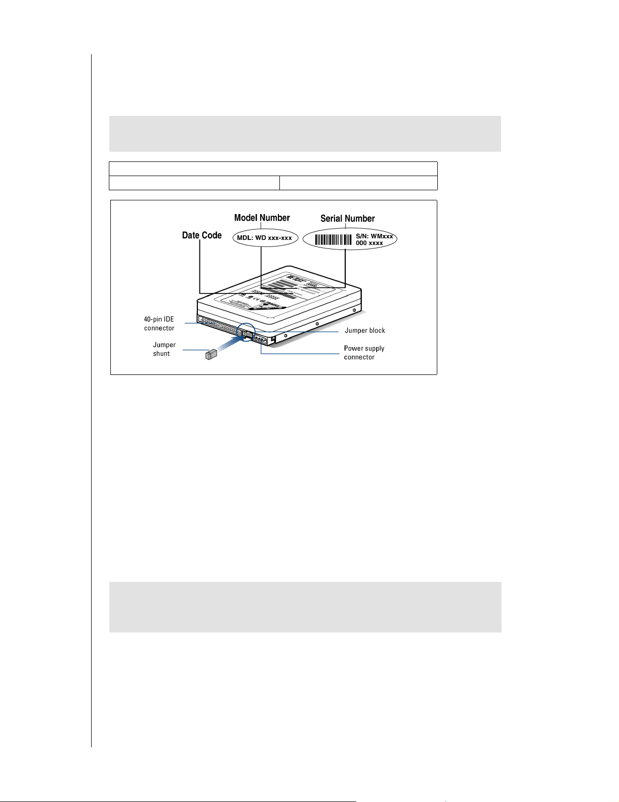
Record Your Hard Drive Information
In the table that follows, write down the serial number, model number, and date code listed
on your new Western Digital hard drive. The complete serial number, model number, and
date code are on the large label at the top of the drive. Please see the illustrations below.
CAUTION: Do not remove, tear, or damage the tape seal or any labels from the
drive; these actions will void the warranty.
Serial Number:
Model Number: Date Code:
Backup Y our Data
Before performing any hardware installation, protect your data by backing up your existing
hard drive before installing your new Western Digital hard drive. Most operating systems
include a backup utility. Refer to your operating system or utilities documentation for
procedures.
Open Your Computer
1. Power down the computer.
2. Unplug the power cord.
3. Remove the computer system outside cover (refer to your computer system manual for
instructions).
IMPORTANT: If your Western Digital hard drive kit came with an Ultra ATA
controller card, proceed to page7. If not, continue with the instructions in the
next section.
BEFORE GETTING STARTED - 2
Page 7
2
WESTERN DIGITAL HARD DRIVE
INSTALLATION GUIDE
Install the Hard Drive without a Controller Card
Determine Appropriate Drive Configuration
The default jumper setting for Western Digital hard drives is Cable Select (CSEL). However,
not all computer systems and motherboards support this setting. You will first need to
determine whether your system or motherboard supports Cable Select as follows:
1. If your system doe s not supp ort Cable S elect or if you ar e uncertain , we re commend u sing
the Master/Slave configuration.
2. If there is an existing IDE device installed, check the jumper settings to see if it is
configured for Cable Select. If it is, then your system supports Cable Select.
3. If the IDE device insta lled is not config ure d for Cable Se lect or if y ou do n ot hav e an IDE
device installed in your computer, check your system documentation or contact your
system/motherboard manufacturer to determine if Cable Select is supported.
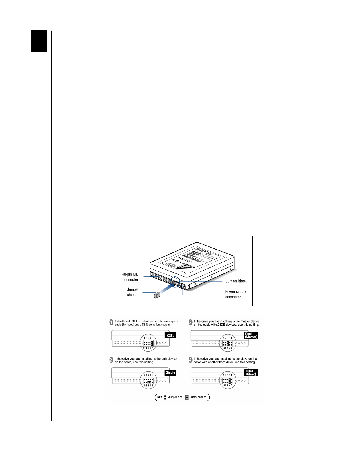
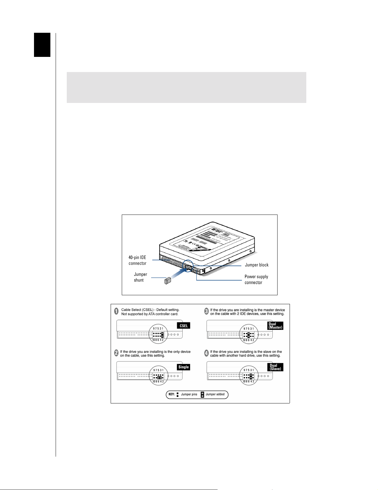
Set the Jumpers
Jumper settings are used to determine the order in which IDE devices (i.e. hard drives,
CD-ROM drive, etc.), attached to a single cable, are detected by the system.
Western Digital IDE hard drives have a 10-pin jumper block located next to the 40-pin IDE
connector on the hard drive. After you have determined the appropriate drive configuration,
you must jumper the drive(s) accordingly. Identify the procedure that corresponds to your
configuration.
10-pin Western Digital Hard Drive
INSTALL THE HARD DRIVE WITHOUT A CONTROLLER CARD - 3
Page 8

WESTERN DIGITAL HARD DRIVE
INSTALLATION GUIDE
Cable Select Configuration
Cable Select requires a special cable (included in your kit). If your system supports Cable
Select, there is no need to reposition the jumper shunt on the drive. If you are installing your
new Western Digital hard drive with an existing IDE drive on the cable, make sure that the
other drive is als o jumpe red a s Cable Se lect. I f you r system does not su pport C able S elect or if
you are uncertain, use the Master/Slave configuration.
Standard Jumper Settings
If you determined that yo u r sys tem does no t supp ort Ca ble S el ect or if yo u ar e unce rtai n, use
the following information to properly jumper your new Western Digital IDE hard drive.
NOTE: Not all hard drive manufacturers use the same jumper configurations. If you are
installing your new Western Digital hard drive along with a non Western Digital hard
drive, obtain jumper setting information from the original hard drive manufacturer.
Single Configuration
Single - Installing the new drive as the only drive in the system:
If installing you r new W e stern Di gital har d drive as th e only IDE device on the cable, then
move the jumper shunt on the drive to pins 4 and 6.
Master/Slave Configuration
To set up the Maste r/Slav e configurat ion, one device on the cable must be jumpere d as M aster
(designated as the primary device) and the other jumpered as Slave (designated as the
secondary device).
If multiple IDE ports a re used, each p ort has its ow n Master/S lave configura tion. The primary
IDE port is ordered first, then the secondary, and so forth. Therefore, it is possible to have
two Master drives and two Slave drives.
Master - Installing the new drive as the primary drive:
If installing your new Western Digital hard drive as the Master drive on the cable with two
IDE devices, then move the jumper on the drive to pins 5 and 6. Next configure the
jumper on the other IDE device as Slave.
Slave - Installing the new drive as the secondary drive:
If installing your new Western Digital har d driv e as the se con dary drive on the cabl e with
two IDE devices, mo v e the ju mper sh unt o n the driv e to pin s 3 and 4. N e xt con figur e the
jumper on the other IDE device as Master.
INSTALL THE HARD DRIVE WITHOUT A CONTROLLER CARD - 4
Page 9
WESTERN DIGITAL HARD DRIVE
Install the Hard Drive
IMPORTANT: Your new Western D igi tal har d dri ve must be ins talle d usin g the
40-pin, 80 conductor cable included in the kit.
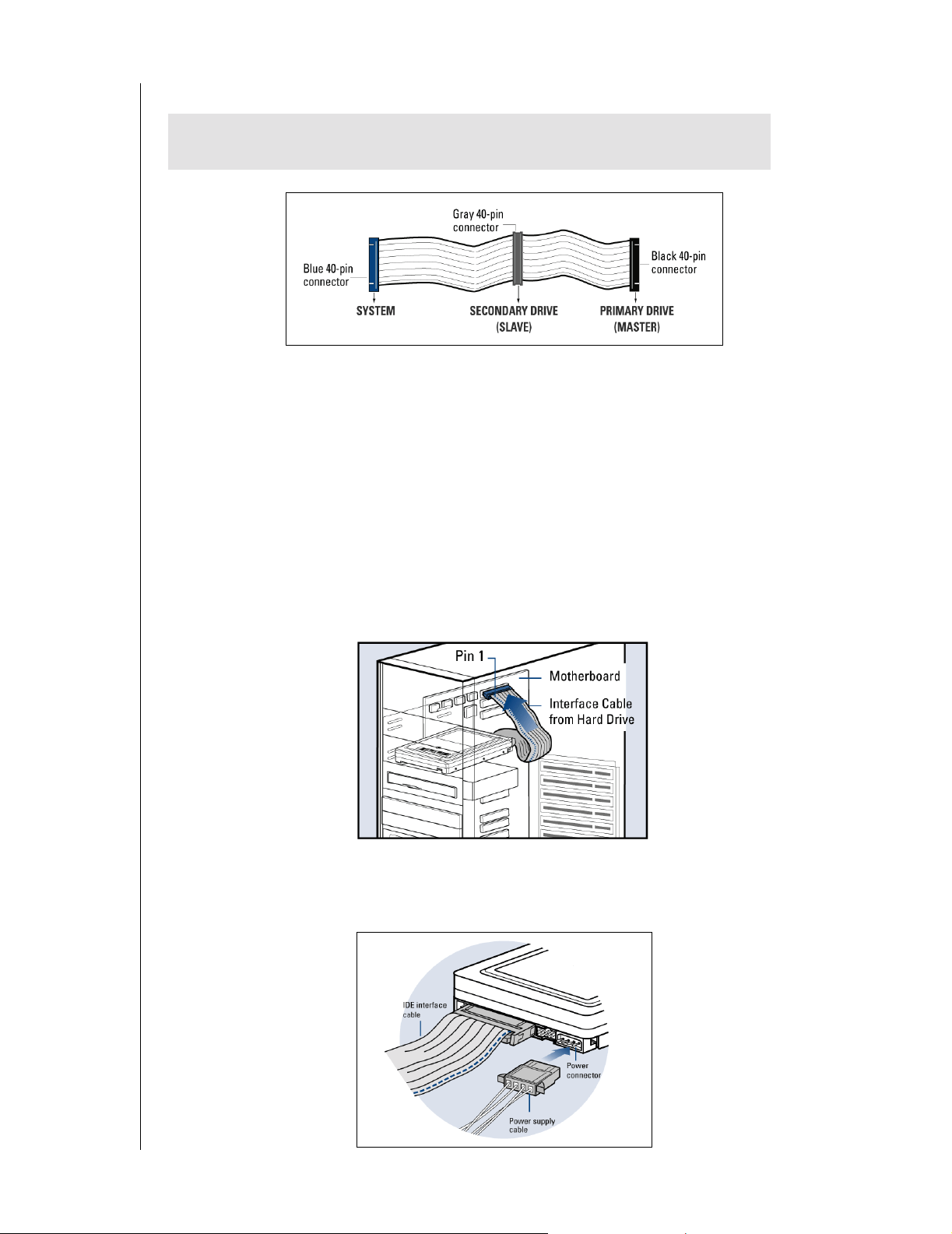
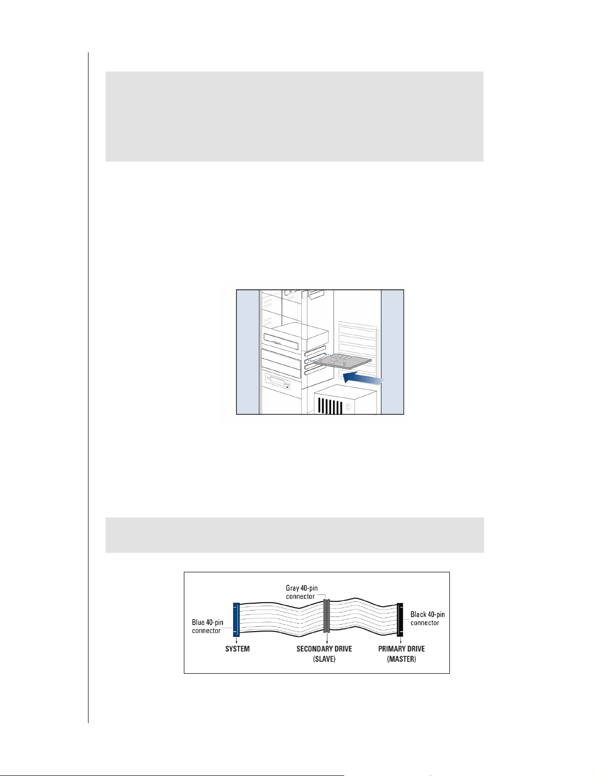
1. Connect the IDE Interface Cable to the Hard Drive(s).
a) If installing the hard drive as the only drive on the cable:
Connect the black connector of the IDE interface cable to the drive.
b) If installing two drives on the same IDE interface cable:
INSTALLATION GUIDE
Configure the bootable drive as Master and the other drive as Slave; then connect the
Master drive to th e black conn ector of th e IDE int erface cable a nd the S lav e driv e to the
gray connector.
2. Connect the IDE Interface Cable to the Motherboard: Attach the blue end of the IDE
interface cable to the 40-pin connector on the motherboard. Match pin 1 on the IDE
interface cable to the connector on the motherboard..
3. Connect the Power Supply Cable: Attach the computer system power supply cable to
the 4-pin power conn ector on the back of your new Western Digital hard drive. The 4-pin
connector is keyed to ensure proper insertion.
INSTALL THE HARD DRIVE WITHOUT A CONTROLLER CARD - 5
Page 10
WESTERN DIGITAL HARD DRIVE
INSTALLATION GUIDE
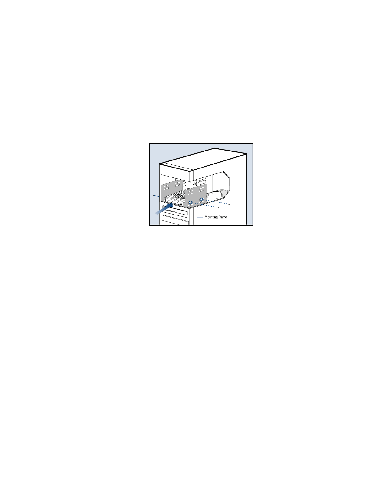
4. Secure the Hard Drive:
a) If securing the hard drive in a 3.5-inch drive bay,
Secure the Western Digital hard drive in an available drive bay (typicall y adjace nt to the
floppy disk drive) using the four mounting screws provided. Mounting brackets are not
required.
NOTE: For proper grounding, be sure to use all four screws.
b) If securing the hard drive in a 5.25-inch drive bay,
You will first need to install 5.25-inch mounting hardware in order to properly mount
the hard drive. If you do not have mounting brackets contact your system manufacturer
or your local computer dealer or call Western Digital technical support.
Power On Your Computer
1. Replace the system cove r, reconnect the power cord, and p o w er on the system . At startup ,
the computer will display all the devices detected on the system.
2. If the drive you installed is not detected, restart the computer.
3. At startup, run the CMOS Setup program. Refer to your system manual for instructions.
4. Select Auto Config drive type.
5. Enable LBA or Translation. Most systems manufactured after 1995 support LBA.
6. This concludes the hard drive installation process.
7. To set up and copy files, proceed to "Data Lifeguard Install Software" page 14.
Register Your Product
Take advantage of Western Digital special offers and pro duct upda tes by registering your n ew
hard drive online at www.wdc.com/products/registration.
INSTALL THE HARD DRIVE WITHOUT A CONTROLLER CARD - 6
Page 11
3
WESTERN DIGITAL HARD DRIVE
INSTALLATION GUIDE
Install the Hard Drive with a Controller Card
Set the Jumpers
IMPORTANT: This sections applies to the Western Digital hard drives that
came with an Ultra ATA controlle r card. I f your har d drive ki t did not come with
a controller card, you must follow the procedures on page 3.
The default setting for your new Western Digital hard drive is Cable Select (CSEL), which
requires a special cable (included in your kit). However, the Ultra ATA controller card does
not support this setting. To use the Ultra A TA controller card with your new Western Digital
hard drive, y ou m ust change t he ju mper s ettin g. The a pprop riat e jumpe r se tting for y our n ew
hard drive will va ry dependin g on yo ur drive co nfi gur at ion. Identify your drive configuration
and jumper your new Western Digital hard drive to the recommended setting.
NOTE: Both Master/Slave and Cable Select configurations refer to having multiple
devices attached to the same IDE i nterfa ce cable. I f yo u ar e connecti ng onl y one de vice to
the IDE interface cable, then the device is considered to be a Single drive.
Western Digital IDE hard drives have a 10-pin jumper block located next to the 40-pin IDE
connector on the hard drive.
10-pin Western Digital Hard Drive
INSTALL THE HARD DRIVE WITH A CONTROLLER CARD - 7
Page 12
WESTERN DIGITAL HARD DRIVE
INSTALLATION GUIDE
Install the Controller Card
IMPORTANT (Windows NT 4.x/2000/XP Users Only): Hard drives
connected to the Ultra ATA controller card will not boot into the Windows
operating system wi thout driver sup port. If you wish to use your current bo otable
hard drive with an existing W indows opera ting system on th e controller card, yo u
must first install the drivers onto the old drive prior to installing your new
Western Digital hard drive. Proceed to "Install Ultra ATA Drivers" on page 11.
The Western Digital Ultra ATA controller card fits into any available 32-bit PCI (must be
PCI 2.1 or 2.2 compliant) expansion slot on your system motherboard.
1. Turn off the computer, unplug the power cord from the system, and remove the outside
cover.
2. Remove the outside slot cover of an available 32-bit PCI slot on the motherboard.
3. Install the controller card into the open slot. Handle the controller by the sides only to
avoid touching the circuit board components.
4. Secure the controller card bracket to the system case.
NOTE: If you wish to connect the hard drive activity LED to your new Western Digital
hard drive, refer to your system manual for instructions.
Install the Hard Drive
IMPORTANT: Your new Western Digital hard drive must be installed using the
40-pin, 80 conductor cable included in the kit.
INSTALL THE HARD DRIVE WITH A CONTROLLER CARD - 8
Page 13

WESTERN DIGITAL HARD DRIVE
INSTALLATION GUIDE
1. Connect the IDE Interface Cable to Hard Drive(s):
a) If installing the hard drive as the only device on the cable,
Connect the black connector of the IDE interface cable to the drive and connect the
blue end of the IDE interface cable to the IDE connector (IDE 1) on the controller card.
Proceed to step 3.
b) If installing two drives on the same IDE interface cable,
-Configure your new Western Digital hard drive as Master and the other drive as Slave.
-Connect the black connector to the new IDE interface cable to the Master drive.
-Connect the grey connector to the Slave drive.
-Connect the blue end of the new IDE interface cable to the IDE connector (IDE 1) on
the controller card.
2. Connect the Power Supply Cable: Attach the computer syste m power supply cable to the
4-pin power connector on the back of your new Western Digital hard drive. The 4-pin
connector is keyed to ensure proper insertion.
3. Secure the Hard Drive:
a) If securing the hard drive in a 3.5-inch drive bay,
Secure the Western Digital hard drive in an available drive bay (typicall y adjace nt to the
floppy disk drive) using the four mounting screws provided. Mounting brackets are not
required.
NOTE: For proper grounding, be sure to use ALL FOUR screws.
INSTALL THE HARD DRIVE WITH A CONTROLLER CARD - 9
Page 14

WESTERN DIGITAL HARD DRIVE
INSTALLATION GUIDE
b) If securing the hard drive in a 5.25-inch drive bay,
You will first need to install 5.25-inch mounting hardware in order to properly mount
the hard drive. If you do not have mounting brackets contact your system manufacturer
or your local computer dealer or call Western Digital technical support.
4. Reconnect the power cord and power on the computer: Make sure that the controller
card is properly seated before powering on the computer.
INSTALL THE HARD DRIVE WITH A CONTROLLER CARD - 1 0
Page 15

WESTERN DIGITAL HARD DRIVE
INSTALLATION GUIDE
Install the Ultra ATA Drivers
Driver installation instructions will vary depending on your operating system, whether the
operating system is already installed or is a new install. Locate the appropriate procedure for
your own operating system setup and carefully follow the directions.
IMPORTANT: If you wish to move the boo t drive with an existing W indow s OS
to the controller card, load the Ultra ATA drivers on this drive while it is still
connected to the existing hard drive controller on the system motherboard. Do
not connect any hard drives to the controller card before completing this step.
I. Using data from an existing drive with Windows NT 4.x/2000/XP already installed
1. After installing the Ultra ATA controller card and rebooting your system, a New
Hardware Found dialog box will appear. Choose Add New Hardware Wizard from the
list, then press Enter .
2. Choose the SCSI Controller from the hardware list that appears in the menu.
3. In the Install D rivers dialog box, select Have Disk.
4. When prompted, insert the Ultra ATA drivers diskette into the floppy disk drive.
5. When the dialog box appears, select Win2000 Ultra TX2 IDE Controller from the list
and click Enter .
6. Follow the onscreen directions, then Windows will restart or shutdown for the driver
installation to take effect.
II. Using data from an existing drive with Windows 98/Me already installed
1. After installing the Ultra ATA controller card and connecting your Western Digital hard
drive, power up the system and boot into Windows.
2. The Add New Hardware Wizard will appear, indicating that a PCI Mass Storage
Controller has been found.
3. Click Next, and when prompted, choose Search for a better driver than the one your
device is using now.
4. Click Next and select Specify a location.
5. Insert the the Ultra ATA drivers diskette into the floppy disk drive.
6. Click Next. A message informing you that "Windows has found Win9x-ME Ultra TX2
IDE Controller" should appear.
7. Click Next, then Finish, then Yes when asked to restart computer to finish drivers
installation.
INSTALL THE HARD DRIVE WITH A CONTROLLER CARD - 1 1
Page 16

WESTERN DIGITAL HARD DRIVE
INSTALLATION GUIDE
III. New Install - Windows NT 4.x/2000/XP
1. Choose from the following media types to install Windows.
a) Floppy Install: Boot the computer with the Windows installation diskettes.
b) Floppy-less Install: Boot from the diskette and type WINNT. After files have been
copied, the system will reboot. On the reboot, press F6 after the message "Setup is
inspecting your computer’s hardware configuration..." appears.
c) CD-ROM Install: Boot from the CD-ROM disk and press F6 after the message "Press
F6 if you need to install third party SCSI or RAID driver" appears.
2. Press S to specify an additional device at the "Windows 2000 Setup" window.
3. Select Promi se Ultra TX2 Controller from the list and click Enter.
4. When prompted, insert the Ultra ATA drivers diskette into the floppy disk drive.
5. Follo w the on scre en dir ection s to install driv er files an d to conti nue Win do ws ins tallati on.
6. If your new Western Digital hard drive is the only drive installed in your system, replace
your system cover and this concludes the hard drive installation process. Otherwise,
proceed to "Set Up and Copy Files" on page 13.
IV. New Install - Windows 98/Me
1. After installing the Ultra ATA controller card, boot to the Data Lifeguard Tools diskette
and follow the onscreen directions to configure the hard drive.
2. Install Windows 98/Me.
3. After installation, go the Start menu, select Settings, and click on Control Panel.
4. In the Control Panel window, double-click on the System icon, and select the Device
Manager tab.
5. In the hierarchical display under "Other Devices" is a listing for PCI Mass Storage
Controller. Select it and click on the Properties button.
6. Select the Drivers tab in the Properties window, choose Update Driver and then click
Next.
7. Select Search for a better driver than the one your device is using new (Recommended),
and click Next.
8. When prompted, insert the the Ultra ATA drivers diskette into the floppy disk drive.
9. Click Next. A message informing you that Windows has found Win9x-ME Ultra TX2
IDE Controller should appear.
10. Click Next, then Finish, then Yes when asked to restart computer to finish drivers
installation.
11. If your new Western Digital hard drive is the only drive installed in your system, replace
your system cover and this concludes the hard drive installation process. Otherwise
proceed to "Set Up and Copy Files" on page 13.
INSTALL THE HARD DRIVE WITH A CONTROLLER CARD - 1 2
Page 17

WESTERN DIGITAL HARD DRIVE
INSTALLATION GUIDE
Set Up and Copy Files
NOTE: This section applies only if you have an existing hard drive connected to your
computer.
1. Power down the system and disconnect the power cord.
2. Disconnect the old drive and old IDE interface cable from the motherboard.
3. Verify that the old drive is jumpered as Slave.
4. Locate the new IDE interface cable th at is connected to the n ew drive and connect its gray
end to the old drive. Both drives are now connected to the controller card.
5. Insert the Data Lifeguard Tools diskette into the floppy drive.
6. Reconnect the power cord and power on the computer. The system will boot to the
diskette.
7. At the introduction screen, select Insta ll Drive and follow the instructions as prompted.
8. Accept the license agreement and select Drive to Drive Copy, then Entire Drive.
9. Choose your old hard drive as the Source and your new Western Digital drive on the
Ultra ATA controller card bus as the Destination.
10. Select Automatically R esize Partitions and click Finish.
11. Replace your system cover and restart the system when prompted. This concludes the
hard drive installation process.
IMPORTANT: If you wish to remove your old drive at this time, you must
change the jumper setting on your new Western Digital hard drive to Single.
Refer to "Set the Jumpers" on page 7 for instructions to jumper your hard drive.
If you prefer to keep your old hard drive and use it as additional storage, make
sure that your new Western Digital hard drive and operating system are working
properly. Once you are certain and satisfied with the operation of the new drive,
back up your old drive and delete its contents.
Register Your Product
Take advantage of Western Digital special offers and pro duct upda tes by registering your n ew
hard drive online at www.wdc.com/products/registration.
INSTALL THE HARD DRIVE WITH A CONTROLLER CARD - 1 3
Page 18

4
WESTERN DIGITAL HARD DRIVE
INSTALLATION GUIDE
Data Lifeguard Install Software
The Data Lifeguard Install software included on the Data Lifeguard Tools diskette that ships
with your Western Digital hard drive serves to:
! Copy the contents of an existing hard drive onto your new hard drive.
! Copy system files needed to boot your new hard drive.
! Partition and format your new hard drive.
! Overcome the 137 GB, 32 GB, and 8.4 GB system BIOS limitations.
Operating System Compatibility
WARNING: Using an operating syste m not listed below co uld res ult in data l oss.
Your new Western Digital hard drives supports the following operating systems:
! Windows XP, Windows 2000, and Windows NT 4.0
! Windows Me and Windows 98 (all versions)
! Macintosh OS 8.6 or later (for drives smaller than 137 GB)
Data Lifeguard Install software can be used with the following operating systems:
! Windows XP, Windows 2000, and Windows NT 4.0
! Windows Me and Windows 98 (all versions)
Before partitioning and formatting your hard drive, you must tell the system what type of
hardware you are using. This is referred to as “configuring the system BIOS.” Your computer
system provides an initial setup utility (CMOS Setup) for that purpose.
Each system BIOS is different. The information supplied here is not meant to be followed
step-by-step but is provided as a guideline. Refer to your system manual for details.
If you have an older system, it may be necessary for you to upgrade your system BIOS, install
an ATA controller card, or use the included Data Lifeguard Tools software to access the full
capacity of your hard drive (see "Operating System and System BIOS Limitations" on
page 24).
IMPORTANT: The most current versio n of D ata Lifeg uard Tools can be used to
partition and format with most AT A controller car ds. H oweve r , in some cases you
may need to use FDISK to com ple te dri ve se tup. To download the last version of
Data Lifeguard Tools, go to support.wdc.com.
DATA LIFEGUARD INSTALL SOFTWARE - 14
Page 19

WESTERN DIGITAL HARD DRIVE
INSTALLATION GUIDE
Consider the following capacity points and dates:
System BIOS Dates BIOS Support Is s ues
Prior to August 1994 May not support hard drives larger than 528 MB
Prior to February 1996 May not support hard drives larger than 2.1 GB
Prior to January 1998 May not support hard drives larger than 8.4 GB
Prior to June 1999 May not support hard drives larger than 32 GB
To configure your system BIOS:
1. Enter your CMOS setup program (sometimes called the Setup program). Systems vary,
but pressing one of these keys s hould gain acce ss to y our CM OS set up: F1, F2, or Delete.
Refer to your system manual for instructions.
NOTE: During your system boot, a message is typica lly display ed after the me mory count
indicating how to enter Setup. If your s yste m doe s not re sp ond (lo cks up) on initi al boot ,
see "Alternate Jumper Settings" on page26.
2. Find any IDE Autodetection option that may be pre sent in y o ur BIOS. If g ive n a choice ,
select the LBA option and enable it. In some cases, LBA will be an option under IDE
Translation Mode. In other systems, Autodetection is preselected.
3. Enable options such as LBA or Translation Mode available in most current syste m BIOSs.
If you do not have either option, you must use Data Lifeguard Install to install your new
hard drive, upgrade the system BIOS, or install an ATA controller card with onboard
BIOS that supports the full drive capacity.
NOTE: If your system BIOS does not have an auto config drive type or does not show full
capacity, disable LBA, select User Defined, and enter 1023 cylinders, 16 heads, and 63
sectors for the drive parameters. Selecting User Defined ensures that the Data Lifeguard
Install software will install on your system.
If your system BIOS does not have auto config or User Defined, select Type 9. Selecting
Type 9 ensures that Data Lifeguard Install will install on your system.
Installing the Hard Drive with Windows NT 4.x/2000/XP
The Data Lifeguard Install software is not needed to install your new Western Digital hard
drive under the following operating systems: Windows XP, Windows 2000, and Windows
NT 4.0. However, it may be used to determine whether the BIOS of your computer system
will support the full capacity of your new hard drive. Please boot from the Data Lifeguard
Tools diskette and follow the recommendations for BIOS support and, if necessary, proceed
with the installation after upgrading your BIOS.
Install a Single Hard Drive:
1. Boot to Windows XP, 2000, or NT 4.0
2. Follow the directions in the installation prompt.
DATA LIFEGUARD INSTALL SOFTWARE - 15
Page 20

WESTERN DIGITAL HARD DRIVE
INSTALLATION GUIDE
Install an Additional Hard Drive in Windows:
Window s XP
1. Click the Start button and point to Control Panel > Performance and Maintenance >
Administrative Tools.
2. Double-click on the Computer Management icon and select Disk Management on the
left side.
3. Right-click on your new hard drive and proceed with partitioning and formatting.
Windows 2000
1. Click the Start button and point to Settings > Control Panel > Administrative Tools.
2. Double-click on the Computer Management icon and select Disk Management on the
left side.
3. Right-click on your new hard drive to proceed with partitioning and formatting.
Windows NT
1. Click the Start button and point to Programs > Administrative Tools > Computer
Management.
2. Select Disk Management on the left side.
3. Right-click on your new hard drive to proceed with partitioning and formatting.
Disabling Floppy Boot Protection
1. After the installation, reboot or power on your system with the Data Lifeguard Tools
diskette in your floppy disk drive.
2. Select Install Drive from the main menu and click Next.
3. At the main menu of Install, select Advanced Options and click Next.
4. Select EZ-BIOS Setup from the Advanced Options menu and highlight the appropriate
hard drive.
5. Click on EZ-BIOS settings at the bottom of the screen.
6. Click the button next to Floppy Boot Protection to disable.
7. Select Apply settings and click Done.
8. Exit Data Lifeguard Install and remove the diskette from the floppy disk drive.
9. Reboot your system.
DATA LIFEGUARD INSTALL SOFTWARE - 16
Page 21

WESTERN DIGITAL HARD DRIVE
INSTALLATION GUIDE
Using Data Lifeguard Install Software
Follow the steps outlined below to set up your hard drive.
1. Insert the Data Lifeguard Tools diskette into your floppy disk drive.
2. Reboot or power on the system.
3. The Data Lifeguard Tools main menu displays. Click Install Drive to continue.
4. Data Lifeguard will attempt to detect hard drive(s) and available disk space.
5. When an unformatted drive is detected, click Yes to continue.
NOTE: If the Data Lifeguard Tools Diagnostic utility reports no Western Digital drives
present, the hard drive may not be properly detected. Check the previous steps regarding
proper cable connection and jumper settings.
6. The Data Lifeguard Options screen displays. The following three choices are available:
A. Partition and Format
B. Drive to Drive Copy
C. Advanced Options
A. Partition and Format
IMPORTANT: D ata Lifegu ard I nstall co pies system files need ed to boot th e hard
drive. It does not install the operating system. If the operating system is not
installed, you need t o complete th e operating system inst allation afte r configuring
the Data Lifeguard Install software.
1. Select P artition and Format from the main menu and click Next.
2. Click on the hard drive you wish to configure and click Next.
3. If you wish to copy from an existing hard drive to your new drive, select No and click
Next. If Yes, select the source drive and click Next.
4. The Part ition De finition m enu will appear a nd you wi ll be given two option s to config ure
the partitions on your drive.
-Select Standard Partition to create the minimum number of partitions allowed by the
operating system. Western Digital recommends this option.
-Select Advanced Users to customize the number of desired partitions and its sizes. You
can also select the file type of either NTFS or FAT32.
5. Click Finish to partition and format the drive.
DATA LIFEGUARD INSTALL SOFTWARE - 17
Page 22

WESTERN DIGITAL HARD DRIVE
INSTALLATION GUIDE
B. Drive to Drive Copy
1. Select the Drive to Drive Copy from the main menu and click Next to proceed.
2. Select from two methods of copy on the destination drive with either Entire Drive or
Selective P artition. Click Next.
3. Select the source drive (the drive that you want to copy from).
4. Select the destination drive (the drive that you want to copy to).
5. Click Next to continue with drive to drive copy.
C. Advanced Options
1. Select Advanced Opti ons from the main menu and click Next to proceed.
2. The menu will appear and you will be given three options.
-Select EZ-BIOS Setup to configure EZ-BIOS settings for a drive. Simply highlight the
drive and click on either Uninstall EZ-BIOS or EZ-BIOS Settings.
-Select Backup/Restore Track Zero to restore the boot track 0 if damaged. Track 0
contains the partition table and boot code. A backup is automatically made when Data
Lifeguard is used to set up your drive.
-Select Remove 63 Sector O ffset to remo ve Disk Ma nager data offset by 63 sectors. If the
Disk Manager boot codes exists, it is removed also.
3. Click Done after selection to return to the main menu.
IMPORTANT: Backup/Restore Track Zero and Remove 63 Sector Offset
options are for advanced users only. Consult with Western Digital Technical
Support for more information.
DATA LIFEGUARD INSTALL SOFTWARE - 18
Page 23

5
WESTERN DIGITAL HARD DRIVE
INSTALLATION GUIDE
Data Lifeguard Tools
Western Digital provides a set of har d driv e ut ili tie s ca lled Da ta Lifegua r d Tools to assist with
hard drive installation, drive management, and repair.
Data Lifeguard Tools Function
Data Lifeguard Diagnostics Identifies and repairs most drive errors
Data Lifeguard BIOS Check Provides information for technical support
Data Lifeguard Ultra ATA
Management
Manages Ultra A TA 100 functions (including AT A
66 and 33)
This section contains information on these programs:
! Data Lifeguard Diagnostics
! Data Lifeguard BIOS Check (available for download at support.wdc.com)
! Data Lifeguard Ultra ATA Management
Data Lifeguard Diagnostics
Data Lifeguard Diagno s tics is included on the D ata Lif eguard Tools diskette. This utility was
designed especially for Western Digital hard drives to diagnose and fix most common hard
drive problems.
When to use Data Lifeguard Diagnostics
! If the hard drive reports errors.
! If you are unable to access files on the hard drive.
! If another diagnostic utility such as SCA NDISK, CHKDI SK, or DEFRA G r eports e rrors
on the hard drive.
Using Data Lifeguard Diagnostics
Data Lifeguard Dia gnosti cs does not ov erwrite data on the ha rd driv e duri ng the scan . If used
properly, it will not result in data loss. Always back up your data before running any
diagnostic utility.
1. Insert the Data Lifeguard Tools diskette into the floppy disk drive.
2. Reboot or power on the system.
CAUTION: Data Lifeguard is for use in DOS only. Do not use within any other
operating system or DOS shell.
3. The Data Lifeguard Tools Welcome screen displays. Click Data Lifeguard Utilities to
continue.
4. After the Data Lifeguard Tools main menu appears, select Diagnostics to proceed and
view the license agreement.
DATA LIFEGUARD TOOLS - 19
Page 24

WESTERN DIGITAL HARD DRIVE
INSTALLATION GUIDE
5. From the Diagnostics menu, choose Select Drive and View Status to display a list of all
drives installed and the current status of each drive. Test each drive separately.
NOTE: Code 0202 indicates the drive has not y et bee n tested. All drive s displ ay this co de
when first selected for testing.
CAUTION: Do not select the Write Zeros to Drive option unless instructed to
do so by qualified technical support personnel. This option will erase all data on
the drive.
6. Use the Up/Down arrow keys to highlight the desired drive and press Enter to return to
the main menu. The Hard Drive Recognition window displays information about the
selected drive.
-If the Hard Drive Recognition window displays the correct drive information, continue
with step 7.
-If the Hard Drive Recognition window displays incorrect information, then Data
Lifeguard Diagnostics is not communicating with the hard drive. Check your BIOS
setup, all cables connected to the hard drive, and the jumper settings on the hard drive.
7. There are two test options on the Data Lifeguard Diagnostics main menu—Quick Test
and Extended Test.
-Quick Test accesses Data Lifeguard information stored on the drive during offline scans
and verifies a defect-free status or recommends the Extended Test. The Quick Test test
takes approximately 90 seconds.
-Extended Test begins checking the drive for defects at your request and presents the
results in approximately 10 to 40 minutes.
8. Press R to test the drive. When the test is complete, the Verify Drive window displays.
Data Lifeguard Diagnostics reports the status of the hard drive with status messages and
descriptions as follows:
Status Message Description
No Errors Detected For This
Drive
Non-WD Drive Detected Data Lifeguard Diagnostics cannot return a non-Western Digital hard
Contact WD Tech Support The hard drive is damaged and cannot be restored to a defect-free
The hard drive is defect free. The problem is related to the BIOS, corrupt
operating system files, or a virus.
drive to defect-free status. Contact your hard drive manufacturer.
or
The latest release of WD Data Lifeguard Tools are not installed.
Download latest version from our product support Web site at
support.wdc.com.
status, and it should be replaced. Write down the Final Code number
and message. Call Western Digital Tec hnical Support.
Restore the Hard Drive to a
Defect-Free Status
The hard drive has errors. Use the Repair Drive option to attempt to
repair the hard drive. Data on the hard drive is lost only when tracks are
relocated, not when sectors are relocated. A warning message displays
whenever this occurs. Relocate tracks only after you ha ve backed
up the data on the hard drive. After completing the Repair Drive
option, Data Lifeguard Diagnostics scans the drive to verify the hard
drive's defect-free status.
DATA LIFEGUARD TOOLS - 20
Page 25

WESTERN DIGITAL HARD DRIVE
INSTALLATION GUIDE
Follow the instructions that relate to your status message. Click Enter to return to Data
Lifeguard Diagnostics main menu.
9. To close, select Quit from the main menu. A message displays pro mpt ing y ou to res et t he
system to reinitialize the BIOS and hard drive(s). This is best accomplished by powering
off the system for 5 seconds.
10. Remove the diskette from the floppy disk drive and power on the system.
Data Lifeguard BIOS Check
Data Lifeguard BIOS Check is available for download at support.wdc.com. The utility
software:
! Determines system BIOS support for large capacity hard drives.
! Identifies all IDE devices in the system.
! Reports capacity, serial number, model number, etc.
Using Data Lifeguard BIOS Check
1. Double-click on the executable file to run Data Lifeguard BIOS Check program.
2. The introduction screen displays and will begin detecting all hard drives connected to
your system.
3. After BIOS Check has finished testing, carefully follow the on-screen directions.
NOTE: BIOS Check may not support some controller cards.
Data Lifeguard Ultra A TA Management
This utility software is designed to enable or disable the Ultra ATA capability on Western
Digital hard drives that support this feature as well as allows you to select other Ultra ATA
configurations that best suit your system.
Requirements for Ultra ATA/100
! The host system chipset and BIOS or add-in controller card must support Ultra ATA/
100.
! The hard drive must support Ultra ATA/100.
! A 40-pin, 80 conductor IDE cable must be attached to the host system and the hard
drive.
! The operating system must be enabled for DMA transfers.
If you are unsure about your system’s capabilities, contact your system motherboard or
controller card manufacturer.
For more in forma tio n ab out usin g D a ta Li fegua r d U l tra ATA Management, visit our product
support Web site at support.wdc.com or contact Western Digital Technical Support.
Using Data Lifeguard Ultra ATA Management
1. Insert the Data Lifeguard Tools diskette into the floppy disk drive.
DATA LIFEGUARD TOOLS - 21
Page 26

WESTERN DIGITAL HARD DRIVE
INSTALLATION GUIDE
2. Reboot or power on the system. Do not run Data Lifeguard Ultra ATA Management
while the Windows operating system is active.
3. The Data Lifeguard Tools Welcome screen displays. Click Data Lifeguard Utilities to
continue.
4. After the Data Lifeguard mai n menu displays, click Ultra AT A Management and carefully
follow the on-screen directions.
DATA LIFEGUARD TOOLS - 22
Page 27

6
WESTERN DIGITAL HARD DRIVE
INSTALLATION GUIDE
Install the Hard D r ive in a Macintosh System
You can install two IDE/ATA hard drives on the same cable with the Master/Slave jumper
configuration in the following Macintosh systems:
! Power Mac G4 and higher
! Power Mac G3 (blue and white colored, limited to certain configurations)
! Power Mac G3 All-in-One
A Power Mac with a U-shaped mounting bracket installed in the rear drive bay is capable of
supporting dual IDE/ATA drives, allowing two drives to be installed in that bay. For more
information on Master/Slave support on Power Macs G3/G4, refer to AppleCare
Knowledgebase Article 24342 at www.apple.com.
If your system does not support the Master/Slave configuration, you will be limited to
installing one IDE/ATA device per channel (for a maximum of two IDE/ATA devices).
The following is a summary of the steps necessary to install a hard drive less than 137 GB as a
secondary hard drive in a Power Mac.
IMPORTANT: For alternative setup instructions and hard drive compatibility,
refer to your original Apple Setup Guide or go to www.apple.com/support for
more documentation.
1. Since Cable Select is the default jumper setting of your Western Digital hard drive, you
must change the configuration to Sl ave (see page7 for a diagram of the jumper block. The
drive that came with the Macintosh is already designated as Master (Master ID=0, Slave
ID=1).
NOTE: Cable Select mode is not supported by Macintosh’s built-in IDE/ATA controller.
2. Install the hard drive in your Macintosh system with the Apple-supplied interface cable.
3. Use the Apple Disk Utility to format and partition the drive. The utility is located on the
Macintosh operating system CD.
INSTALL THE HARD DRIVE IN A MACINTOSH SYSTEM - 23
Page 28

7
WESTERN DIGITAL HARD DRIVE
INSTALLATION GUIDE
Troubleshooting
This section contains information on the following topics:
! Operating System and System BIOS Limitations
! Hard Drive Formatting Issues
! Alternate Jumper Settings
! Frequently Asked Questions
! Non Western Digital Support Information
Operating System and BIOS Limitations
Computer operating systems and system BIOSs have separate limitations that are related to
specific hard drive capacities. The capacity points that can affect how your operating system
and system BIOS support your hard drive are 137.4 GB, 32 GB, and 8.4 GB. The following
are brief descriptions of each limitation.
137.4 GB Barrier
The current standard for the IDE/ATA interface uses a 28-bit addressing which cannot
recognize more than 137.4 GB of storage. To overcome this capacity barrier, hard drives
higher than this capacity have adopted a 48-bit addressing system which can be supported in
newer computer systems with updated controller chips, BIOS codes, and operating system
drivers (refer to your system do cumenta tion for mor e det ails). M ost sys tems, ho wev er, require
the use of a 48-bit LBA supported controller card to fully recognize higher capacity hard
drives and maximize transfer rates.
Current Windows operating systems (98, NT, Me, 2000, XP) do not support hard drives
larger than 137 GB. Western Digital has included a controller card and drive rs to addre ss this
operating system limitation. During installation, hard drives larger than 137 GB must be
attached to the controller card and the drivers for your operating system must be loaded
properly to avoid the risk of data loss.
Certain operating s ystem util ities such a s ScanDi sk and De frag, may not function pr operly o n
the drive partitions exceeding 137 GB. Creating multiple partitions less than 137 GB will
allow proper functionality.
32 GB Barrier
Some BIOSs released before June 1999 stall with drives larger than 32 GB. If you are
installing a hard drive larger than 32 GB and your system stalls before floppy or hard drive
boot can take place, you may have a system BIOS that is incompatible with this larger hard
drive. Follow these instructions only if your system stalls when adding a drive larger than
32 GB.
Recommended Solution: Contact your system or motherboard manufacturer for a BIOS
upgrade.
Interim Solution: Follow the steps below using the Western Digital Data Lifeguard Tools
diskette included in your hard drive kit. With this sol ution, you will not be able to warm boot
your system (<CTRL><ALT><DEL>) or Restart from the Windows menu. You must always
choose Shut Down from the menu and power down the system when prompted.
1. Jumper your hard drive appropriately.
TROUBLESHOOTING - 24
Page 29

WESTERN DIGITAL HARD DRIVE
INSTALLATION GUIDE
2. Use the Data Lifeguard Install software to access the full capacity of the hard drive with
these jumper settings. To run Data Lifeguard Install:
-Insert the Data Lifeguard Tools diskette into your floppy disk drive.
-Boot your system and use the Data Lifeguard Install software (see page 17 for detailed
instructions). This will install EZ-BIOS on your system and allow your system to access
the full capacity of your hard drive.
8.4 GB Barrier
There is an 8.4 GB hard drive limitation on some traditional system BIOSs. To access the full
capacity of 8.4 GB and larger hard drives, your system BIOS must support extended BIOS
functions, and your operating system must recognize extended BIOS functions. It is difficult
to determine if your system BIOS supports 8.4 GB or larger hard drives. We recommend
using the latest Data Lifeguard Install software to ensure support of the full capacity of your
hard drive. Visit our product support Web site at support.wdc.com for the latest version.
Other options are to upgrade your system BIOS or purchase a controller card. Contact your
system or motherboard manufacturer for a BIOS Flash or more information.
The following operating systems recognize extended BIOS functions.
! Windows 98 and Windows 98 Second Edition
! Windows Me
! Windows NT with Service Pack 4 or later
! Windows 2000
! Windows XP
The following operating systems do not recognize extended BIOS functions. See the table
that follows for limitations and exceptions.
! DOS 6.xx and earlier
! Windows 3.1x
! Windows NT
! Novell NetWare
! OS/2 Warp
Operating System Limitations and Exceptions
DOS 6.xx and earlier
Windows 3.1x
Windows 95 Does not support drives larger than 32 GB.
Windows NT Windows NT 4.0 with Service Pack 4 or later
8.4 GB maximum capacity limit. Hard drive capacities
larger than 8.4 GB are recognized as 8025MB.
recognizes hard drives larger than 8.4 GB.
TROUBLESHOOTING - 25
Page 30

WESTERN DIGITAL HARD DRIVE
INSTALLATION GUIDE
Hard Drive Formatting Issues with Windows 95/98/Me
For 32 GB drives and higher, several limitations with the Windows operating system
programs have been identified and confirmed by Microsoft.
Windows Me
Windows Millennium may exhibit the following problem:
! FORMAT displays the size of partitions or logical drives larger than 64 GB incorrectly -
Q263045*
Windows 98 (All Versions)
Windows 98 may exhibit the following problems:
! FDISK does not recognize the full size of hard drives larger than 64 GB - Q263044*
! FORMAT displays the size of partitions or logical drives larger than 64 GB incorrectly -
Q263045*
! SCANDISK reports errors on hard drives larger than 32 GB - Q243450*
Windows 95 (All Versions)
Windows 95 doe s not supp ort har d drive capacitie s gre ater than 32 GB. U sers sh ould upgrade
to Windows 2000, Windows Millennium, Windows 98, or Windows NT 4.0 Service Pack 4
(or higher).
*Microsoft Knowledge Base Article ID Number. To download the Microsoft fix for each
problem, go to support.microsoft.com and enter the specific article ID number.
Alternate Jumper Settings
Alternate jumper settings are provided on WD Caviar drives to overcome the system BIOS
limitations. These jumper s et tings ca use th e dri v e to report a smaller capacity to wo rk ar o und
the BIOS issues. If yo u use these jumper sett ings, you MUST in stall Data L ifeguar d EZ-BIOS
software to access the drive’s full capacity.
NOTE: Cable Select cannot be used when alternative jumpers are selected.
TROUBLESHOOTING - 26
Page 31

WESTERN DIGITAL HARD DRIVE
INSTALLATION GUIDE
Frequently Asked Questions
This section contains answers to common hard drive installation questions by our customers.
To search the Western Digital technical support knowledgebase for our complete list of
frequently asked questions, visit our product support Web site at support.wdc.com.
The cables are properly connected and the jumper settings are correct, but the system
BIOS cannot recognize the hard drive.
Always check first to make sure that you have the latest BIOS update installed for your system
motherboard. If you have an older computer system, the BIOS may "hang" or "freeze" while
auto detecting the drive. You may need to use the alternate jumper settings (see “Alternate
Jumper Settings” on page 26).
If you have determined that this is a BIOS limitation issue, follow the instructions below.
1. Enter the system BIOS.
NOTE: Typically a message is displayed o n the scr een a fter the m emory count of the boot
process, telling you ho w to en ter S etup (S ystem BIO S). Each sy stem' s BIOS is con figur ed
differently, but the primary keystrokes used to enter the System BIOS are F1, F2, or
Delete. For specific information on how to enter your system BIOS and make the
necessary changes referenced above, refer to your motherboard or system manual or the
manufacturer directly.
2. Select User or User defined drive type and enter 1023 cylinders, 16 heads, and 63 sectors
for the drive parameters.
3. Next, you will have one of two Mode options, LBA Mode or IDE Translation Mode.
Select the option appropriate to your computer BIOS which disables Translation. This
can be done by disabling LBA or choosing Normal or Standard CHS mode.
4. Your BIOS may have more setting s other tha n Cyl inders, H eads, a nd Sectors ; if so, simp ly
enter 0 for them.
5. Once the above is completed , the driv e siz e should sho w the capaci ty as bei ng 502 MB o r
528 MB. This is normal. The above settings simple tricks your BIOS into thinking the
hard drive is smaller than it really is, allowing the computer to boot with the hard drive
connected. The full capacity of the hard drive will be available once the Data Lifeguard
Tools diskette is used to install, partition, and format the hard drive.
My hard drive is making clicking noises. What is wrong?
There are seve ral potent ial problems tha t can cause clicki ng sounds. F irst, the drive itself could
be failing or has failed. Other reasons could include a faulty data cable, data corruption,
incorrect BIOS settings, or in some cases, a virus infection. Follow these suggestions to
diagnose the problem.
1. Power the system down and disconnect the IDE ribbon cable to the drive making the
noise. Leave the power cable attached.
2. When you attach the drive to the power supply with the 40-pin data cable detached, does
the clicking continue?
Yes - The drive has failed and needs to be replaced. Other symptoms generally associated
with clicking include:
TROUBLESHOOTING - 27
Page 32

WESTERN DIGITAL HARD DRIVE
INSTALLATION GUIDE
! The Auto-Detect feature in the BIOS does not detect a drive.
! FDISK does not report a dri v e pr es en t ev e n if the drive's parameters are en te r ed m an uall y.
In these cases, refer to our product support Web site at support.wdc.com to obta in a R MA
(Returned Material Authorization).
No - A faulty cable is a likely cause . R eplace t he cable to see if th is r esolve s the i ssue. If this
makes no difference, the drive has most likely experienced some form of data corruption,
possibly a virus. In this case the Auto-Detect will generally still detect the drive and
FDISK will also report a drive present. Run the Data Lifeguard Diagnostic Tool from a
clean (virus free) write-protected floppy and test the drive. If the drive does not fail, then
the Write Zeros option may be needed to remove all software from the drive.
Unfortunately, all data on the drive will be lost.
I installed a large drive into an older computer, but it does not see the full capacity. What
happened?
If the system only recognizes 528 MB, 2.1 GB, 8.4 GB, 32 GB, or 64 G B of the hard drive or
something signifi can tly le ss t ha n the a ctual ca pacity of t he h ar d drive , y our s yste m B IO S ma y
not support the hard drive capacity. Here are some possible solutions:
1. Check with the system or motherboard manufacturer to see if they have a BIOS upgrade
available for your system.
2. Purchase an ATA controller card (included with Western Digital hard drives larger than
137 GB). The controller card has two benefits. It will have its own BIOS to support the
drive and enable the higher transfer rates the drive is capable of attaining. Western
Digital's Online Store at store.wdc.com has a complete selection of ATA controller cards
that allow you to access the full capa city of the hard drive and use the hi gher transfer rate s.
3. A third option is to use our Data Lifeguard Tools diskette to set up the drive. The tools
will install an o v erlay on the driv e t o suppo rt its full ca pacit y. An overlay is a pr ogra m tha t
installs on the boot sector of your hard drive and enables full access of your hard drive's
capacity.
When installing a drive larger than 64 GB in Windows 9X, FDISK/FORMAT shows either
the wrong or incomplete capacity. Why?
Microsoft Windows 95/98/98SE has a limitation that incorrectly displays the capacity for
drives larger than 64 GB. This li mitat ion is no t the r esult of data los s. The partiti onin g utility
FDISK and the formatting utility FORMAT will incorrectly sho w the capacity of th e drive as
minus 64 GB. For example, if the drive is 80 GB, the capacity is shown as 16 GB. Microsoft
has acknowledged this issue and has released a fix for FDISK.
Also, depending on the particular utility used, the capacity of the hard drive can be reported
in either decimal gigabytes, where 1 GB = 1,000,000,000 bytes or in binary gigabytes where 1
GB = 1,073,741,824 bytes. FDISK reports a drive's capacity in binary gigabytes. For example,
a WD 200 GB hard drive's capacity will be reported as approximately 186 binary gigabytes.
NOTE: If Data Lifeguard Tools is used to partition and format the drive, no fixes are
required. Make sure you are using Data Lifeguard Tools version 10.0 or above.
TROUBLESHOOTING - 28
Page 33

WESTERN DIGITAL HARD DRIVE
INSTALLATION GUIDE
Western Digital Service and Support
If you need additional information or help during installation or normal use of this product,
visit our product support Web site at support.wdc.com and send an email to Western Digital
Technical Support. You may also call using the phone numbers listed below. When calling for
support, have your Western Digital hard drive serial number and system hardware and
software versions available.
USA/Canada/Outside USA
(Central Time)
Telephone Numbers 800.ASK.4WDC +31.20.446.7651
Monday - Thursday 9:00 am - 7:00 pm 8:00 am - 5:00 pm
Friday 9:00 am - 6:00 pm 8:00 am - 3:00 pm
Saturday 8:00 am - 11:45 am
1:00 pm - 5:00 pm
(Central European Time)
Europe
TROUBLESHOOTING - 29
Page 34

8
WESTERN DIGITAL HARD DRIVE
INSTALLATION GUIDE
Appendix
Regulatory Co mpliance
This appendix contains information on the following topics:
! Agency Approvals
! Radio Frequency Interference Statement
! Warranty Information
Agency Approvals
Western Digital hard drives meet the standards of the following regulatory agencies:
Federal Communication Commission
Verified to comply with FCC Rules for Radiated and Conducted Emission, Part 15, Subpart
B, for Class B Equipment.
Underwriters Laboratories
UL-Standard 1950, Standard for Safety of Information Technology Equipment including
Electrical Business Equipment (File E101559).
Canadian Standards Associ ation
CSA-Standard C22.2, No. 950-M89, Standard for Safety of Information Technology
Equipment including Electrical Business Equipment (File LR68850).
TUV Essen Laboratories
IEC-950 (EN60950) Standard for Safety of Information Technology Equipment including
Electrical Business Equipment.
CE Compliance For Europe
Verified to comply with EN55022:1998 for RF Emissions and EN55024:1998 for generic
Immunity as applicable
Radio Frequency Interference Statement
FCC Notice
This Western Digital product has been verified to comply with the limits for a Class B
computing device pursuant to subpart B Part 15 of FCC rules. This does not guarantee that
interference will not occur in individual installations. Western Digital is not responsible for
any television, radio, or other interference caused by unauthorized modifications to this
product.
If interference problems do occur, consult the system equipment owner's manual for
suggestions. These su g ges ti ons ma y incl u de r e locati on of the comp ute r sys tem away fro m th e
television or radio, or placing the computer AC power connection on a different circuit or
outlet.
APPENDIX - 30
Page 35

WESTERN DIGITAL HARD DRIVE
INSTALLATION GUIDE
CSA Notice
Le prent appareil numérique n'émet pas de bruits radioélectriques dépassant les limites
applicables aux appareils numériques de la classe B préscrites dans le Règlement sur le
brouillage radioélectrique édicté par le ministère des Communications du Canada.
This digital apparatus does not exceed the Class B limits for radio noise for digital apparatus
set out in the Radio Interference Regulations of the Canadian Department of
Communications.
Warranty Information
Obtaining Service
Western Digital (WD) values your business and always strives to provide you the very best of
service. No limited warranty is provided by WD unless your WD Product (Product) was
purchased from an authorized distributor or authorized reseller. Distributors may sell
Products to resellers who then sell Products to end users. See below for warranty information
or obtaining service. No warranty service is provided unless the Product is returned to an
authorized return center in the region (Americas, Europe-Middle East-Africa, or Asia Pacific)
where the Product was first shipped by WD. If your Product was purchased as a component
integrated within a system by a system manufacturer, no limited warranty is provided by WD.
Contact the place of purchase or the system manufacturer directly for warranty service.
Return Material Authorization
No Product may be returned directly to WD without first contacting WD for a Return
Material Autho rizati on (RMA) num ber. If it is determined that the Product may be defective,
you will be given an RMA number and instructions for Product return. An unauthorized
return, i.e. one for which an RMA number has not been issued, will be returned to you at
your expense. Autho riz ed re turns ar e to b e shippe d pre-p aid an d insur ed to t he addr ess o n the
RMA in an approv ed shipping con tainer. Y our original box and packaging mate rials shoul d be
kept for storing or shipping your Product. For information on approved shipping containers,
visit our product support Web site at support.wdc.com.
Limited Warranty
WD's limited warranty provides that, subject to the following limitations, each Product will
be free from defects in mat erial and workmanship and wi ll conform t o WD's specification fo r
the particular Product.
Duration of Warranty
The warranty period commences from the date of manufacture appearing on the Product
label of the original Product purchase. To verify this period for your Product, visit product
support Web site at support.wdc.com. In the United States, some states do not allow
limitations on ho w long imp lied warranti es last, s o the abo v e limit ation ma y not app ly to yo u.
APPENDIX - 31
Page 36

WESTERN DIGITAL HARD DRIVE
INSTALLATION GUIDE
Other Warranty Limitations
For further important information on limitations on WD's warranty, see below and visit our
product support Web site at support.wdc.com and click on Warranty Policy.
Disclaimer of Warranties
There are no warranties which extend beyond the face of the WD limited warranty. WD
disclaims all other warranties, expres s or implied, regarding the P roducts, including any
implied warranties of merchantability, fitness for a particular purpose or noninfringement.
In the United States, some laws do not allow the exclusion of the implied warranties.
Your Use of the Product
WD will have no liability for any Product returned if WD determines that:
! The product was stolen from WD.
! The asserted defect:
A. is not present,
B. cannot reasonably be fixed because of damage occurring when the Product is in the
possession of someone other than WD, or
C. is attributable to misuse, improper installation, alteration (including removing or
obliterating labels), accident or mishandling while in the possession of someone
other than WD.
! The Product was not sold to you as new.
Limitation of Remedies
Your exclusive remedy for any defective Product is limited to the repair or replacement of
the defective Product.
WD may elect which remedy or combination of remedies to provide in its sole discretion.
WD shall have a reasonable time after determining that a defective Product exists to repair or
replace a defective Product. WD's replacement Product under its limited warranty will be
manufactured from new and serviceable used parts. WD's warranty applies to repaired or
replaced Products for the balance of the applicable period of the original warranty or ninety
days from the date of shipment of a repaired or replaced Product, whichever is longer.
Limitation of Damages
WD's entire liability for any defective Product shall in no event exceed the purchase price
for the defective Product. This limitation applies even if WD cannot or does not repair or
replace any defective Pr oduct and your excl usive remedy fails of its essential purpose.
No Consequential or Other Damages
WD has no liability for general, consequential, incidental or special damages. These include
loss of recorded data, the cost of recovery of lost data, lost profits and the cost of the
installation or removal of any Products, the installation of replacement Products, and any
inspection, testing, or redesign caused by any defect or by the repair or replacement of
Products arising from a defect in any Product.
APPENDIX - 32
Page 37

WESTERN DIGITAL HARD DRIVE
INSTALLATION GUIDE
In the United States, some states do not allow exclusion or limitation of incidental or
consequential damages, so the limitations above may not apply to you. This warranty gives
you specific legal rights, and you may also have other rights which vary from state to state.
Online Warranty Inquiry
For further warranty information and inquiries, visit our product support Web site at
support.wdc.com and click on Warranty P olicy. The new online Warranty Inquiry System will
provide warranty status based on the serial number of the Product.
Extended Warranty
Certain WD products may be eligible for purchase of additional or extended warranty
options. For further details, visit our product support Web site at support.wdc.com and click
on Warranty Policy.
APPENDIX - 33
 Loading...