


MD-42
Omvandlare RS-232 – RS-422/485
Converter RS-232 – RS-422/485
RS-232 – RS-422/485 Wandler
INSTALLATIONSANVISNING
INSTALLATION MANUAL
INSTALLATIONS ANLEITUNG
6152-2002
www.westermo.se
MD-42 AC
MD-42 DC
©
Westermo Teleindustri AB • 1999 • Rev. B
Galvanic
Isolation
Transient
Protection
Balanced
Transmission
CE
Approved
8 6152-2002
Specifications
Transmission Asynchronous, full/half duplex or simplex
Interface 1 EIA RS-232-C/CCITT V.24,
9-position D-sub female / Screw-terminal
Interface 2 EIA RS-422/RS-485/CCITT V.11
Data rate Up to 115.2 kbit/s
Indicators Power, TD, RD, RTS, CTS, DCD
Insulation Galvanic insulation with opto-coupler (data transmission)
and transformer (supply)
Insulation voltage 1500V
Overvoltage protection Mains: Breakdown voltage 430V at 230V AC
and 230V at 115V AC*
Interface 2: Breakdown voltage transmitter
and receiver 7V
Surge capacity 0.6 kW for 1ms
Power supply 115V*/230VAC +15/–10% 48–62Hz
Fuse 100 mA fast 5x20 mm
Power consumption Max 4VA at 115V*/230V AC
Temperature range 5-50°C, ambient temperature
Humidity 0–95% RH, non-condensing
Dimensions 55x100x128 mm (BxHxD)
Weight AC 0.5 kg, DC 0.3 kg
Mounting At DIN-rail 35 mm
* MD-42 115V AC only
1
23456789
S3:1-6 S2:1-6
123 4 5
MD-42 DC
V24/RS-232-C
RS-422/RS-485/V11
CONVERTER
LINE CONNECTION
-
+
TD
RD
RTSCTS
DCD DT
DS SG
103 104 105 106 109 108 107 102
12-36V DC
POWER
R+ R- T+ T-
PW
V24/RS-232-C
CONNECTION
Warning!
Do not open connected unit

96052-2001
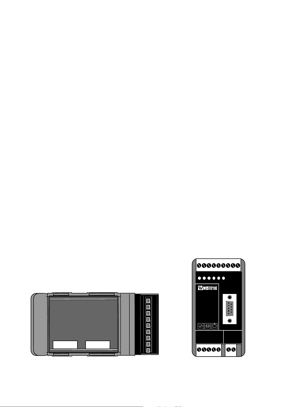
Switch settings
The MD-42 can through different switch settings be adapted to a vareity of running
conditions. To set switches, open the plastic case by removing the top cover.
S2 Selection of signal activating the transmitter
Selection of signal controlling DCD
Selection of CTS delay
S3 Selection of termination with fail-safe 1)
Selection of 2- or 4-wire communication
Transmitter
Factory settings
Transmitter
Activated
by
RTS RTS RTS
RTS Always high
DTR DTR
DTR Always high
RTS
DTR
DTR
CTS
contolled
by
DCD
contolled
by
S2
S2
S2
S2
S3
ON
123456
ON
123456
ON
123456
Termination (4-wire)
Termination (2-wire)
No termination
S3
S3
S3
ON
123456
ON
123456
ON
123456
Termination
with fail-safe
1)
ON
123456
Always high Always lowAlways active
S2
ON
123456
Always high Always highAlways active
S2
ON
123456
ON
123456
CTS-delay
0ms
S2
S2
20ms
S2
ON
123456
ON
123456
Selection of 2- or 4-wire
4-wire
S3
2-wire
S3
ON
123456
ON
123456
ON
123456
1) The fail-safe function forces the
signal state of the receiver to
OFF when the connected
transmitter is in tri-state
(transmitter inactive).
The receiver located furthest
away shall be terminated.
 Loading...