


EDW-100
User Guide
6616-2203
EDW-100
Westermo Teleindustri AB
©
Serial Adapter
www.westermo.com

Software tools
Related software tools are available in the folder software tools under
technical support on the Westermo website.
Legal information
The contents of this document are provided “as is”. Except as required by applicable
law, no warranties of any kind, either express or implied, including, but not limited to,
the implied warranties of merchantability and fitness for a particular purpose, are made
in relation to the accuracy and reliability or contents of this document. Westermo
reserves the right to revise this document or withdraw it at any time without prior
notice.
Under no circumstances shall Westermo be responsible for any loss of data or income
or any special, incidental, and consequential or indirect damages howsoever caused.
More information about Westermo can be found at the following Internet address:
http://www.westermo.com
2
6616-2203
Safety
!
!
Before using this unit:
Read this manual completely and gather all information on the unit. Make sure
that you understand it fully. Check that your application does not exceed the safe
operating specifications for this unit.
Hazardous voltage may occur within this unit when connected to power supply or
TNV circuits.
Prevent access to hazardous voltage by disconnecting the unit from power supply
and all other electrical connections.
Prevent damage to internal electronics from electrostatic discharges (ESD) by
discharging your body to a grounding point (e.g. use of wrist strap).
Before installation:
This unit should only be installed by qualified personnel.
This unit should be built-in to an apparatus cabinet, or similar, where access is
restricted to service personnel only.
The power supply wiring must be sufficiently fused, and if necessary it must be
possible to disconnect manually from the power supply. Ensure compliance to
national installation regulations.
Branch circuit protection (fuse) is required for this unit with rating not exceeding
20 A.
This unit uses convection cooling. To avoid obstructing the airflow around the
unit, follow the spacing recommendations (see Installation section).
Care recommendations
Follow the care recommendations below to maintain full operation of unit and to fulfil
the warranty obligations.
This unit must not be operating with removed covers or lids.
Do not attempt to disassemble the unit. There are no user serviceable parts inside.
Do not drop, knock or shake the unit, rough handling above the specification may cause
damage to internal circuit boards.
Do not use harsh chemicals, cleaning solvents or strong detergents to clean the unit.
Do not paint the unit. Paint can clog the unit and prevent proper operation.
Do not expose the unit to any kind of liquids (rain, beverages, etc). The unit is not
waterproof. Keep the unit within the specified humidity levels.
Do not use or store the unit in dusty, dirty areas, connectors as well as other mechanical
part may be damaged.
If the unit is not working properly, contact the place of purchase, nearest Westermo
distributor office or Westermo Tech support.
Maintenance
No maintenance is required, as long as the unit is used as intended within the specified
conditions.
6616-2203
3
ATEX and IECEx Information (Applicable for EDW-100 Ex only)
General
This unit is intended for use in Zone 2 hazardous location only.
Marking
Baseefa 14ATEX0294X
II 3 G
Ex nA IIC T4 Gc
IECEx BAS 14.0137X
SPECIAL CONDITION
WARNING – DO NOT SEPARATE WHEN ENERGIZED
Indicate that this unit complies with relevant European standards that are
harmonised with the 94/9/EC Directive (ATEX).
II
3
G
Ex Indicates that this unit is in conformity with relevant European Ex standard(s).
nA
IIC Gas group, a typical gas i hydrogen.
T4
Gc
SPECIAL
CONDITION
Equipment group II.
This unit can be installed in all places with an explosive gas atmosphere other
than mines susceptible to firedamp
Equipment category 3.
A category is the classification according to the required level of protection.
This unit ensures the requisite level of protection during normal operation and
is intended for use in areas in which explosive atmosphere caused by gases,
vapours, mists, or dust mixtures are unlikely to occure or, if they do occure, are
likely to do so only infrequently and for a short periode only.
Indicates protection concerning explosive atmospheres caused by gases, vapours
or mists (G).
Type of protection used.
This unit is a non-sparking device "nA" which is constructed to minimize the
risk of occurence of arcs or sparks capable of creating an ignition hazard during
conditions of normal operation.
Temperature class T4 (T4 = 135°C).
This unit is classified in accordance with its maximum surface temperature
(external and internal).
Equipment protection level Gc (EPL Gc).
Equipment for explosive gas atmospheres, having a "enhanced" level of
protection, which is not a source of ignition in normal operation and which may
have some additional protection to ensure that it remains inactive as an ignition
source in the case of regular expected occurences. EPL Gc are analogous to the
ATEX Categories (Category 3 G = EPL Gc).
This unit has a special condition of use.
The special conditon for safe use contains safety related information that is
necessary for the correct installation and safe use.
4
6616-2203
Ratings
Power 12 – 48 VDC; 250 mA
Ambient temperature –25ºC ≤ Ta ≤ +70ºC
Ingress protection (IP) IP21
Maximum surface temperatur 135ºC (temperature class T4)
Safety Control Drawing
Degree of protection IP 21
Ambient temperature –25°C to +70°C
Installation spacing
1234
1234
Minimum 25 mm above / below
Minimum 10 mm left / right
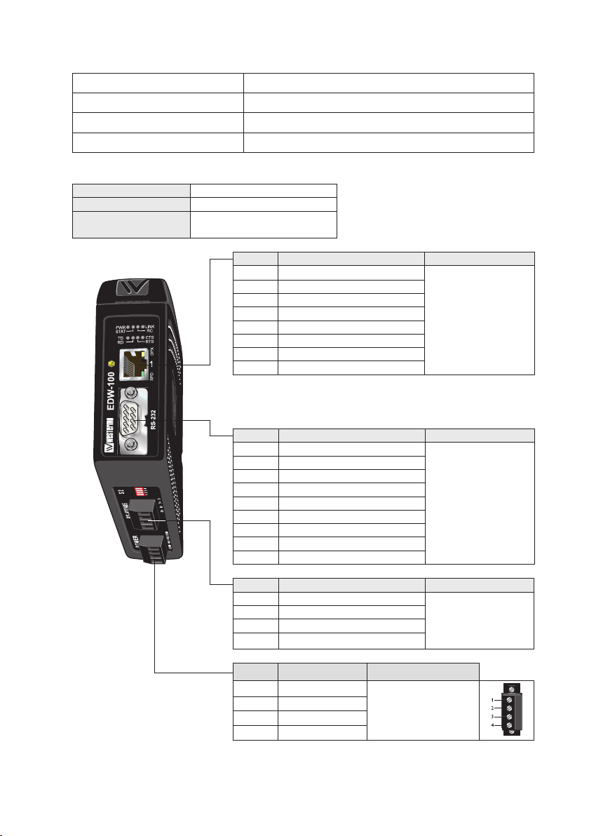
Position Descripton Input / Output values
1 In/Out / TD+
2 In/Out / TD–
3 In/Out / RD+
4 Not connected
5 Not connected
6 In/Out / RD–
7 Not connected
8 Not connected
Galvanically isolated via signal transformer and capacitively
isolated to signal ground through a 3 kV 470 pF capacitor.
See user manual for proven transient protection.
Position Descripton Input /Output values
1 Not connected (DCD)
2 In / Received Data (RD)
3 Out / Transmitted Data (TD)
4 Out / Data Terminal Ready (DTR)
5 – / Signal Ground (SG)
6 In / Data Set Ready (DSR)
7 Out / Request To Send (RTS)
8 In / Clear To Send (CTS)
9 Not connected
U = ± 1 V (4μV/s)
I = ± 20 mA
Data rate:
10/100 Mbit/s
U
= ± 12 Vpk
max
I
= ± 60 mA
max
Data rate:
0.3 – 115.2 kbit/s
6616-2203
Position Descripton Input / Output values
1 In / R+ line RS-422 U
2 In / R– line RS-422
3 In/out / T+ line RS-422/485
4 In/out / T– line RS-422/485
= ± 5 Vpk
max
I
= ± 250 mA
max
Data rate:
0.3 – 115.2 kbit/s
Position Descripton Input values
1 In / Common
2 In / +Voltage A
3 In / +Voltage B
4 In / Common
See section Type tests and environmental conditions in this user
manual for proven transient protection.
U
min/max
I
= 300 mA
max
P
max
= 3 W
= 10 – 60 VDC
5

SPECIAL CONDITION FOR SAFE USE
Ambient temperature:
This unit is designed for use in extreme ambient temperature conditions as follows:
–25ºC ≤ Ta ≤ +70ºC
Installation in an apparatus cabinet:
The equipment must be installed in an area of not more than pollution degree 2 in accordance with
IEC 60664-1, and in an enclosure that provides a minimum degree of pretection of at least IP54 and
complies with the relevant requirements of EN 60079-0 and EN 60079-15.
Secureness of energisation:
External connections to the equipment must not be inserted or removed unless either the area in
which the equipment is installed is known to be non-hazardous, or the circuits connected have been
de-energised.
Resistance to impact:
This unit requires installation in an apparatus cabinet where adequate resistance to impact is
provided by the apparatus cabinet. See "Installation in an apparatus cabinet" above for requirements
on the external apparatus cabinet.
Resistance to light:
This unit requires installation in an apparatus cabinet where it is protected from light (for example
daylight or light from luminaires). See "Installation in an apparatus cabinet" above for requirements
on the external apparatus cabinet.
Secureness of plugs:
When this unit is installed in explosive atmospheres, all connectors must be mechanically secured to
prevent loosening by the use of cable ties or similar.
Conductor temperature:
When this unit is installed in locations with high ambient temperature, special precautions shall be
taken upon the choice of external conductors and the temperature rating of the conductor(s).
Directive 94/9/EC alongside with other directives:
Directive 2004/108/EC (EMC) applies and to assure a safe performance of this unit under the scope
of Directive 94/9/EC, refer to the electromagnetic immunity level specified under "Type tests and
environmental conditions" in this manual.
Standards and date of compliance
ATEX: EN 60079-0: 2012
EN 60079-15: 2012
IECEx: IEC 60079-0: 2011 EDITION 6
IEC 60079-15: 2010 EDITION 4
6
6616-2203
Agency approvals and standards compliance
Type Approval / Compliance
EMC
Safety
ATEX** EN 60079-0 and EN 60079-15
IECEx** IEC 60079-0 and IEC 60079-15
* Applicable for EDW-100 only
** Applicable for EDW-100 Ex only
FCC Part 15.105
Notice:
EN 55022 Notice: Warning
EN 50121-4, Railway signalling and telecommunications apparatus
EN 55022, Emission IT equipment
EN 55024, Immunity IT equipment
EN 61000-6-1, Immunity for residential, commercial and light-industrial environments
EN 61000-6-2, Immunity industrial environments
EN 61000-6-4, Emission industrial environments
IEC 62236-4, Railway signalling and telecommunications apparatus
UL/CSA/IEC/EN 60950-1, IT equipment*
EN 60950-1, IT equipment**
This equipment has been tested and found to comply with the limits for a
Class A digital device, pursuant to Part 15 of the FCC Rules. These limits are
designed to provide reasonable protection against harmful interference when
the equipment is operated in a commercial environment.
This equipment generates, uses, and can radiate radio frequency energy and, if
not installed and used in accordance with the instruction manual, may cause
harmful interference to radio communications. Operation of this equipment
in a residential area is likely to cause harmful interference in which case the
user will be required to correct the interference at his own expense.
This is a class A product. In a domestic environment this product may cause
radio interference in which case the user may be required to take adequate
measures.
6616-2203
7
Org.nr/
1
1
th
Declaration of Conformity, EDW-100 / EDW-100 EX
Westermo Teleindustri AB
Declaration of conformity
The manufacturer Westermo Teleindustri AB
Herewith declares that the product(s)
Type of product Model Art no
Ethernet to serial adapter EDW-100 3616-0020
is in conformity with the following EC directive(s).
No Short name
2004/108/EC Electromagnetic Compatibility (EMC)
94/9/EC 1 Equipment Explosive Atmospheres (ATEX)
2011/65/EU
References of standards applied for this EC declaration of conformity.
No Title Issue
EN 61000-6-1
EN 61000-6-2
EN 61000-6-4 Electromagnetic compatibility – Emission for industrial environments 2007
EN 55022 Information technology equipment - Emission
EN 55024
EN 50121-4 Railway applications - Electromagnetic compatibility
EN 50581 Technical documentation for the assessment of electrical and electronic
EN 60079-0
EN 60079-15
The last two digits of the year in which the CE marking was affixed: 14
SE-640 40 Stora Sundby, Sweden
EDW-100 EX 3616-5020
EDW-120 3616-0010
EDW-120 EX 3616-5010
Restriction of the use of certain hazardous substances in electrical and electronic
equipment (RoHS)
Electromagnetic compatibility – Immunity for residential environments
Electromagnetic compatibility – Immunity for industrial environments
Information technology equipment
Emission and immunity of the signalling and telecommunications apparatus
products with respect to the restriction of hazardous substances
Explosive atmospheres
Equipment – General requirements
Electrical apparatus for explosive gas atmospheres –
Construction, test and marking of type of protection “n” electrical apparatus
-
Immunity
2007
2005
+A1:2011
2010
2010
2006
2012
2012
2012
Pierre Öberg
Technical Manager
3
December 2014
1
Only applicable for EDW-100 EX and EDW-120 EX.
Postadress/Postal address
S-640 40 Stora Sundby 016-428000 016-428001 52 72 79-4 5671-5550 556361-2604 Eskilstuna
Sweden Int+46 16428000 Int+46 16428001
Tel.
Telefax
Postgiro
Bankgiro Corp. identity number Registered office
8
6616-2203
Type tests and environmental conditions
Electromagnetic Compatibility
Phenomena Test Description Test levels
ESD EN 61000-4-2 Enclosure contact ± 6 kV
RF field AM
modulated
RF field 900 MHz ENV 50204 Enclosure 20 V/m pulse modulated 200 Hz, 900 ± 5 MHz
Fast transient EN 61000-4-4
Surge
RF conducted EN 61000-4-6 Signal ports 10 V 80% AM (1 kHz), 0.15 – 80 MHz
Pulse magnetic field EN 61000-4-9 Enclosure 1000 A/m, 6.4 / 16 ms pulse
Voltage dips
and interruption
Radiated emission EN 55022 Enclosure Class A
Conducted emission EN 55022 DC power ports Class B
Dielectric strength EN 60950 Signal port to other
Environmental
Temperature Operating –25 to +70ºC
Humidity Operating 5 to 95% relative humidity
Altitude Operating 2 000 m / 70 kPa
Service life Operating 10 year
Vibration IEC 60068-2-6 Operating 7.5 mm, 5 – 8 Hz
Shock IEC 60068-2-27 Operating 15 g, 11 ms
Packaging
Enclosure
EDW-100 UL 94 PC / ABS Flammability class V-1
EDW-100 Ex – Cabelec CA6141 –
Dimension
W x H x D
Weight 0.2 kg
Degree of protection IEC 529 Enclosure IP 21
Cooling Convection
Mounting On 35 mm DIN-rail
IEC 61000-4-3
EN 61000-4-5 Signal ports
EN 61000-4-29 DC power ports 10 & 100 ms, interruption
FCC part 15 Class A
Enclosure air ± 8 kV
Enclosure 20V/m 80% AM (1 kHz), 80 – 2 000 MHz
Signal ports
Power ports ± 2 kV
unbalanced
Signal ports balanced ± 2 kV line to earth, ± 1 kV line to line
Power ports ± 2 kV line to earth, ± 2 kV line to line
Power ports 10 V 80% AM (1 kHz), 0.15 – 80 MHz
isolated ports
Power port to other
isolated ports
Storage & Transport –40 to +70ºC
Maximum surface
temperature
Storage & Transport 5 to 95% relative humidity
12V/m 80% AM (1 kHz), 2 000 – 2 700 MHz
± 2 kV
± 2 kV line to earth, ± 2 kV line to line
10 ms, 30% reduction
10 ms, 60% reduction
+20% above & –20% below rated voltage
1.5 kVrms 50 Hz 1 min
2 kVrms 50 Hz 1 min
135ºC (temperature class T4)
2 g, 8 – 500 Hz
35 x 121 x 121 mm
6616-2203
9
Introduction
The EDW-100 is an Industrial Ethernet to serial adapter or Ethernet Terminal Server. The
serial interface is selectable between RS-232 and RS-422/485. The Ethernet interface is
10/100BASE-T and supports the following networking protocols: TCP, UDP, ICMP, IGMP,
HTTP, ARP.
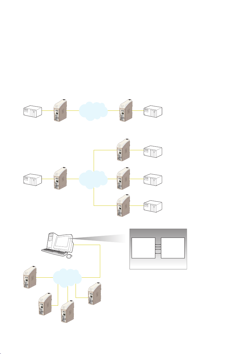
Two EDW-100 can be used to provide a serial point to point link over an Ethernet
network using either UDP or TCP. When using TCP the EDW-100 can be configured as
client or server.
In addition to a transparent serial point-to-point link and ethernet to serial adapter, the
EDW-100 MG can also be configured to act as a Modbus gateway.
Each unit passes data
Serial
Device
Configured
as UDP- or
TCP-server
Network
Configured
as UDP- or
TCP-client
Serial
Device
from its serial interface
to the serial interface
of the other unit. This
enables long distance serial
communication using preexisting networks.
COM5
Network
Broadcast
Multicast
Network Interface
COM255
EDW-100 can also provide a remote serial interface
for a computer connected through a TCP/IP network
using a comport redirection software.
A COM port redirector or customer written
software can be used to create virtual COM ports.
This software will redirect data, originally sent to a
local COM port, to the remote serial interface of the
EDW-100. No changes are required on the computer
application software.
Serial
Master
Network
COM3
COM4
10
Serial
Serial
Serial
Application software
Data to / from COM3
Data to / from COM4
Data to / from COM5
Data to / from COM255
Slave
Slave
Slave
When EDW-100 is used
with the UDP protocol
it is also possible to
communicate one to many
(e.g. master to multiple
slaves), by using a broadcast
address or multicast
addressing
COM port
redirector software
6616-2203
 Loading...