

Page 1
Model No. WL
Visit our website at
www.weslo.com
new products, prizes,
fitness tips, and much more!
Serial No.
Serial Number Decal
TL13921
QUESTIONS?
As a manufacturer, we are
committed to providing complete customer satisfaction. If
you have questions, or if there
are missing parts, we will guarantee complete satisfaction
through direct assistance from
our factory.
TO AVOID DELAYS, PLEASE
CALL DIRECT TO OUR TOLLFREE CUSTOMER HOT LINE.
The trained technicians on our
customer hot line will provide
immediate assistance, free of
charge to you.
USER’S MANUAL
OMER HOT LINE:
CUST
1-800-999-3756
Mon.–Fri., 6 a.m.– 6 p.m. MST
CAUTION
Read all precautions and instruc
tions in this manual before using
this equipment. Save this manual for future reference.
-
Page 2

TABLE OF CONTENTS
IMPORTANT PRECAUTIONS . . . . . . . . . . . . . . . . . . . . . . . . . . . . . . . . . . . . . . . . . . . . . . . . . . . . . . . . . . . . . . . . 2
BEFORE YOU BEGIN . . . . . . . . . . . . . . . . . . . . . . . . . . . . . . . . . . . . . . . . . . . . . . . . . . . . . . . . . . . . . . . . . . . . . . 3
ASSEMBLY . . . . . . . . . . . . . . . . . . . . . . . . . . . . . . . . . . . . . . . . . . . . . . . . . . . . . . . . . . . . . . . . . . . . . . . . . . . . . . 4
TREADMILL OPERATION . . . . . . . . . . . . . . . . . . . . . . . . . . . . . . . . . . . . . . . . . . . . . . . . . . . . . . . . . . . . . . . . . . . 6
MAINTENANCE
CONDITIONING GUIDELINES . . . . . . . . . . . . . . . . . . . . . . . . . . . . . . . . . . . . . . . . . . . . . . . . . . . . . . . . . . . . . . . 9
PART LIST . . . . . . . . . . . . . . . . . . . . . . . . . . . . . . . . . . . . . . . . . . . . . . . . . . . . . . . . . . . . . . . . . . . . . . . . . . . . . . 10
EXPLODED DRAWING . . . . . . . . . . . . . . . . . . . . . . . . . . . . . . . . . . . . . . . . . . . . . . . . . . . . . . . . . . . . . . . . . . . . 11
ORDERING REPLACEMENT PARTS . . . . . . . . . . . . . . . . . . . . . . . . . . . . . . . . . . . . . . . . . . . . . . . . . Back Cover
LIMITED WARRANTY . . . . . . . . . . . . . . . . . . . . . . . . . . . . . . . . . . . . . . . . . . . . . . . . . . . . . . . . . . . . . . Back Cover
AND TROUBLESHOOTING . . . . . . . . . . . . . . . . . . . . . . . . . . . . . . . . . . . . . . . . . . . . . . . . . . . . 8
IMPORTANT PRECAUTIONS
WARNING:
tions before using the treadmill.
1. It is the responsibility of the owner to ensure
that all users of the treadmill are adequately
informed of all warnings and precautions.
2. Use the treadmill only as described in this
manual.
3. This treadmill is intended for in-home use
only. Do not use the treadmill in a commercial, rental, or institutional setting.
4. Place the treadmill on a level surface, with
eight feet of clearance behind it. Place a mat
under the treadmill to protect the floor.
5. Inspect and properly tighten all parts of the
treadmill
immediately.
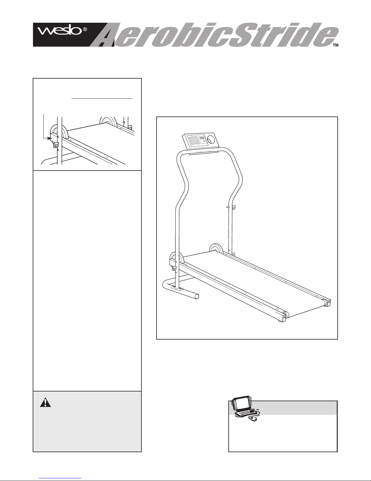
6. The roller guards must be 1/8 inch from the
rear roller (see the drawing on page 3). Adjust
the roller guards, if necessary
7. Keep children under the age of 12 and pets
away from the treadmill at all times.
regularly; replace any worn parts
To reduce the risk of serious injury, read the following important precau-
.
8. The treadmill should not be used by persons
weighing more than 250 pounds. Never allow
more than one person on the treadmill at a
time.
9. Wear appropriate clothing when exercising.
Do not wear loose clothing that could become
caught on the treadmill.
10. Always wear athletic shoes when using the
treadmill; do not use the treadmill with bare
feet, wearing only stockings, or in sandals.
11. Do not use the treadmill if it is not working
properly.
12. Do not place hands or feet under the treadmill while it is in use.
Always hold the handrail when mounting,
13.
dismounting, or exercising on the treadmill.
14. If you feel pain or dizziness at any time while
exercising, stop immediately and begin cooling down.
WARNING: Before beginning this or any exercise program, consult your physician. This
is especially important for persons over the age of 35 or persons with pre-existing health problems.
Read all instructions before using this product. ICON assumes no responsibility for personal injury
or property damage sustained by or through the use of this product.
2
Page 3
BEFORE YOU BEGIN
Thank you for selecting the new WESLO®AEROBIC
STRIDE treadmill. The AEROBIC STRIDE treadmill is
designed to let you enjoy effective cardiovascular
workouts in the comfort and convenience of your
home. And when the AEROBIC STRIDE treadmill is
not in use, it can be folded up, requiring less than half
the space of other treadmills.
For your benefit, read this manual carefully before
using the treadmill. If you have questions after read-
ing this manual, please call our Customer Service
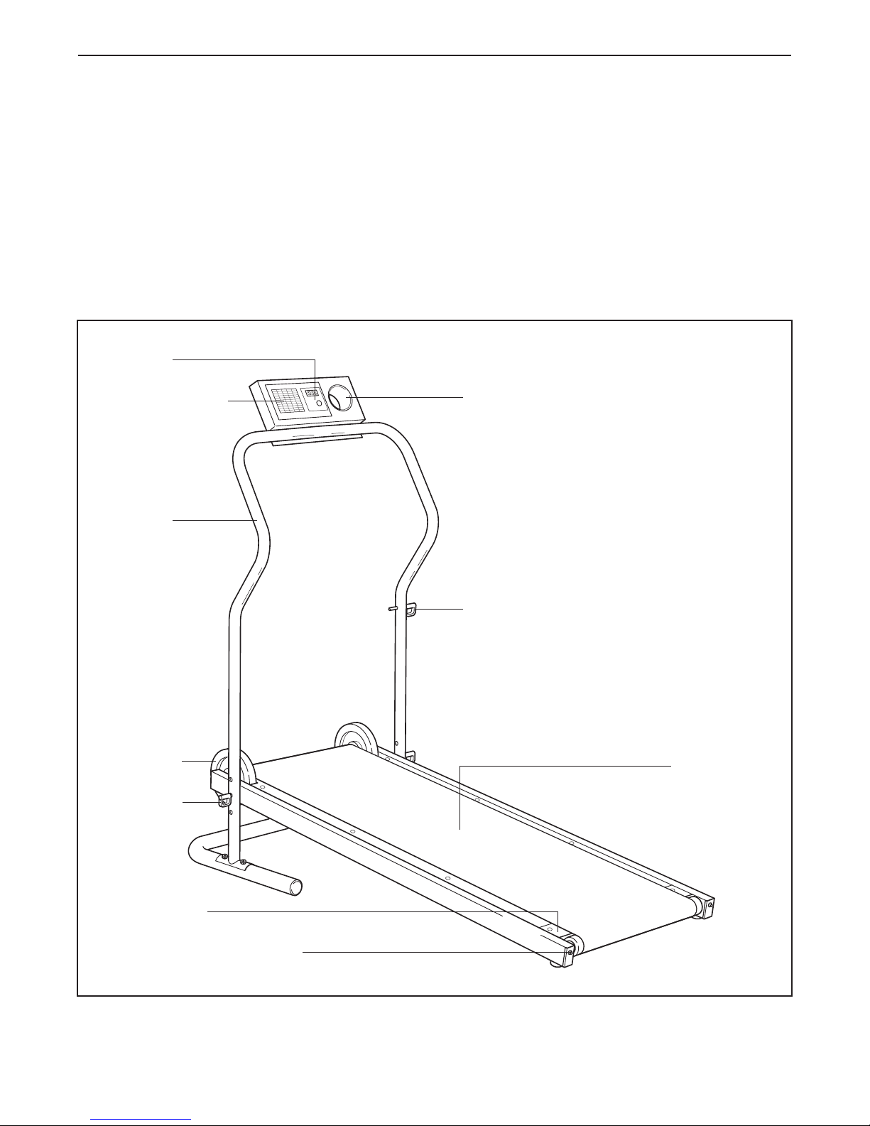
Console
Heart Rate Chart
Handrail
Department toll-free at 1-800-999-3756, Monday
through Friday, 6 a.m. until 6 p.m. Mountain Time
(excluding holidays). To help us assist you, please
note the product model number and serial number
before calling. The model number is WLTL13921. The
serial number can be found on a decal attached to the
treadmill (see the front cover of this manual to find the
location of the decal).
Before reading further, please familiarize yourself with
the parts that are labeled in the drawing below.
ater Bottle Holder
W
(Bottle not included)
Flywheels
Long Pins
Roller Guards
Rear Roller Adjustment Bolts
Short Pin
Walking Belt
3
Page 4
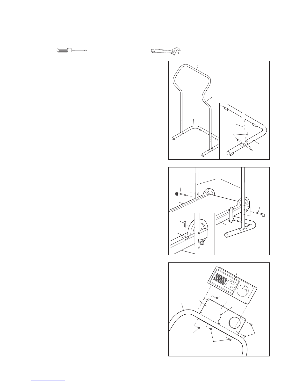
ASSEMBLY
The help of a second person is recommended. Set the treadmill in a cleared area and remove all packing
materials. Do not dispose of the packing materials until assembly is completed. Assembly requires a phillips
screwdriver and an adjustable wrench (not included).
1. Slide the Handrail (6) onto the four welded bolts in the
Base (19) as shown.
See the inset drawing. Attach each side of the Handrail
(6) to the Base (19) with two M8 Nylon Nuts (16).
2. Lift the front of the Frame (32, 35) and align the holes
near the front of the Frame with one of the three sets of
holes in the Handrail (6). Insert the two Long Pins (5)
into the Handrail and the Frame. Make sure that the
Long Pins are fully inserted at the same level.
See the inset drawing. Insert a Cotter Pin (8) into the
hole near the end of each Long Pin (5). Make sure that
the Cotter Pins are fully inserted.
1
2
32
6
19
6
16
19
Bolts
6
5
5
8
35
5
Attach the Console Plate (2) to the Handrail (6) with two
3.
M4 x 16mm Screws (3) as shown. Feed the Reed
Switch Wire (7) up through the indicated hole in the
Console Plate.
Hold the Console (1) near the Console Plate (2). Plug
the Reed Switch W
Feed the excess Reed Switch W
hole in the Console Plate. Attach the Console to the
Console Plate with four M4 x 16mm Screws (3).
careful not to pinch the Reed Switch W
ire (7) into the back of the Console.
ire down through the
Be
ire.
3
6
4
2
3
3
3
1
7
3
Page 5

4. Insert the Reed Switch (7) into the Reed Switch Clip
(14) as shown.
Attach the Reed Switch Clip to the left
side of the Frame (32) with an M4 x 16mm Screw (3).
Do not fully tighten the Screw yet.
4
Top View
Refer to the inset drawing. Locate the Magnet (15) on
the left Flywheel (12). Turn the Flywheel until the
Magnet is aligned with the Reed Switch (7). Slide the
Reed Switch so that there is a 1/8” gap between the
Reed Switch and the Magnet. Then, tighten the M4 x
16mm Screw (3).
5. The Console (1) requires two "AA" batteries (not includ-
ed). Alkaline batteries are recommended. Remove the
Battery Cover (33) by sliding it upward. Insert two batter-
into the battery clip,
ies
making sure that the negative
(–) ends of the batteries are touching the springs in
the battery clip. Insert the battery clip back into the
Console and slide the Battery Cover (33) back into
place.
6. Remove the backing from the Adhesive Clip (37). Press
the Adhesive Clip onto the left side of the Frame (32) in
the indicated location. Press the Allen Wrench (26) into
the Adhesive Clip.
32
5
6
3
12
15
1/8”
14
3
7
7
33
Battery Clip
1
Batteries
Make sure the walking belt is properly tightened (see
SYMPTOM 3 on page 8).
26
7. Make sure that all parts are properly tightened before you use the treadmill. T
pet, place a mat under the treadmill.
37
32
o protect the floor or car
-
5
Page 6

TREADMILL OPERATION
LUBRICATING THE WALKING PLATFORM
Before the treadmill is used, the walking platform
should be lubricated. Open the included lubricant
bottle. Reach under one side of the walking belt as far
as you can, and apply half of the lubricant to the walk
ing platform. Then, reach under the other side of the
walking belt and apply the remainder of the lubricant.
After you have applied the lubricant, walk on the
treadmill for a few minutes to spread the lubricant.
Apply lubricant here
STEP-BY-STEP CONSOLE OPERATION
Follow the steps below to operate the console.
1. Turn on the power.
To turn on the power, press the on/reset button or
-
simply begin walking. When the power is turned on,
the entire display will appear for two seconds. The
console will then be ready for use. Note: If batteries
were just installed, the power will already be on.
2. Follow your progress with the five modes.
When the power is
turned on, the console will automatically scan through five
modes. A flashing
mode indicator will
show which mode is
currently displayed.
The modes are
described below.
• Speed—This mode displays your speed, in miles
per hour.
Mode Indicator
Before the console can be operated, batteries must be
installed (see assembly step 5 on page 5). If there is a
thin sheet of plastic on the console, remove the plastic.
• Time—This mode displays the elapsed time.
• Distance (DIST)—This mode displays the total
number of miles you have walked.
• Fat Calories (FAT CALS)—This mode displays the
approximate number of fat calories you have
burned (see BURNING FAT on page 9).
• Calories (CALS)—This mode displays the approximate number of calories you have burned.
To reset the display, press the on/reset button.
Turn off the power.
3.
To turn off the power, simply wait for a few minutes. If the walking belt is not moved and the con-
sole button is not pressed for a few minutes, the
power will turn off automatically.
6
Page 7

INCLINE ADJUSTMENT
FOLDING THE TREADMILL FOR STORAGE
The incline of the treadmill can be adjusted to any of
three positions. Hold the front of the Frame (32, 35),
and remove the Long Pins (5). Raise or lower the
Frame, align the holes in the Frame with one of the
sets of holes in the Handrail (6), and re-insert the
Long Pins.
inserted at the same level. Refer to the inset drawing. Insert a Cotter Pin (8) into the end of each Long
Pin.
5
Make sure the Long Pins are fully
6
32
5
35
8
5
When the treadmill is not in use, it can be folded to
the compact storage position. CAUTION: You must
be able to safely lift 25 pounds (11 kg) to raise,
lower, or move the treadmill.
1. Hold the treadmill with your hands in the locations
shown below. CAUTION: To decrease the possi-
bility of injury, bend your legs and keep your
back straight. As you raise the treadmill, make
sure to lift with your legs rather than your back.
Raise the treadmill to the vertical position.
1
CAUTION: If the Cotter Pins (8)
are not inserted into the Long Pins (5) as
shown, the Long Pins may slip out, resulting
in injury to the user.
2. Hold the treadmill
securely with your
left hand as
shown. Insert the
Short Pin (4) into
the hole in the
right side of the
Handrail (6) and
into the Frame
(35) as far as it
will go.
LOWERING THE TREADMILL FOR USE
Hold the treadmill securely with your left hand as
1.
shown in drawing 2 above. Pull out the Short Pin
(4). Pivot the treadmill down a few inches and reinsert the Short Pin.
2. Hold the treadmill firmly with both hands, and lower
the treadmill to the floor. CAUTION
the possibility of injury, bend your legs and
keep your back straight.
2
6
35
4
o decrease
: T
7
Page 8

MAINTENANCE AND TROUBLESHOOTING
Most problems can be solved by following the simple steps below. If further assistance is needed, call
our Customer Service Department toll-free at 1-800-999-3756, Monday through Friday
Mountain Time (excluding holidays).
, 6 a.m. until 6 p.m.
SYMPTOM: THE CONSOLE DOES NOT
1.
FUNCTION PROPERLY
a. Replace the batteries in the console (see assem-
bly step 5 on page 5).
b. Make sure that the reed switch is properly adjust-
ed (see assembly step 4 on page 5).
c. Make sure that the reed switch wire is plugged
fully into the back of the console (see assembly
step 3 on page 4).
d. The console, like most electronics, is susceptible
to static electricity build-up caused by certain
types of clothing or by the operation of the treadmill. If the display is blank or gives incorrect readings, apply an anti-static spray to the handrail.
Anti-static spray is available where laundry supplies are sold.
2. SYMPTOM: THE WALKING BELT DOES NOT
MOVE SMOOTHLY
a. If the walk-
ing belt is
overtightened, performance
may be
reduced and
the walking
belt may be
permanently
damaged. Using the allen wrench, turn both rear
roller adjustment bolts counterclockwise 1/4 of a
turn. When the tension of the walking belt is correct, you should be able to lift each side of the
walking belt 2 to 3 inches. Walk on the treadmill
for a few minutes.
properly tightened. Be careful to keep the walking
belt centered.
2"–3"
Repeat until the walking belt is
Walking Belt
Bolts
SYMPTOM: THE WALKING BELT SLIPS OR IS
3.
OFF-CENTER
a. If the walking
belt slips
when walked
on, use the
allen wrench to
turn both
adjustment
bolts clockwise,
1/4 of a turn. When the walking belt is correctly
tightened, you should be able to lift each side of
the walking belt 2 to 3 inches. Walk on the treadmill for a few minutes. Repeat until the walking
belt is properly tightened. Be careful to keep the
walking belt centered.
If the walking
b.
belt has shifted to the left
side, use the
allen wrench to
turn the left
adjustment bolt
clockwise, and
the right adjustment bolt counterclockwise, 1/4 of
a turn each. Be careful not to overtighten the
walking belt. Walk on the treadmill for a few minutes. Repeat until the walking belt is centered.
c. If the walking
belt has shifted to the right
side, use the
allen wrench to
turn the left
adjustment bolt
counterclockwise, and the right adjustment bolt clockwise, 1/4
of a turn each. Be careful not to overtighten the
walking belt. W
utes. Repeat until the walking belt is centered.
alk on the treadmill for a few
min-
8
Page 9

CONDITIONING GUIDELINES
The following guidelines will help you to plan your
exercise program. Remember that proper nutrition and
adequate rest are essential for successful results.
WARNING: Before beginning this
or any exercise program, consult your physician. This is especially important for individuals over the age of 35 or individuals withpreexisting health problems.
WHY EXERCISE?
Exercise has proven essential for good health and
well-being. A well-rounded exercise program helps to
develop a stronger and more efficient heart, improved
respiratory function, increased stamina, better weight
management, increased ability to handle stress, and
greater self-esteem.
EXERCISE INTENSITY
Whether your goal is to burn fat or to strengthen your
cardiovascular system, the key to achieving the
desired results is to exercise with the proper intensity.
The proper intensity level can be found by using your
heart rate as a guide. The chart below shows
recommended heart rates for fat burning and aerobic
exercise.
Burning Fat
To burn fat effectively, you must exercise at the proper
intensity level for a sustained period of time. During
the first few minutes of exercise, your body uses easi
ly accessible
after the first few minutes does your body begin to use
stored fat calories for energy. If your goal is to burn
fat, adjust the intensity of your exercise until your
heart rate is between the lower two numbers in your
training zone as you exercise.
Aerobic Exercise
If your goal is to strengthen your cardiovascular system, your exercise must be “aerobic.” Aerobic exercise
is activity that requires large amounts of oxygen for
prolonged periods of time. This increases the demand
on the heart to pump blood to the muscles, and on the
lungs to oxygenate the blood. For effective aerobic
exercise, adjust the intensity of your exercise until
your heart rate is near the highest number in your training zone.
HOW TO MEASURE YOUR HEART RATE
To measure your
heart rate, stop exercising and place two
fingers on your wrist
as shown. Take a
six-second heartbeat
count, and multiply
the result by ten to
find your heart rate.
(A six-second count is used because your heart rate
drops quickly when you stop exercising.) If your heart
rate is too high, decrease the intensity of your exer
cise. If your heart rate is too low, increase the intensity
of your exercise.
carbohydrate calories for energy
. Only
-
-
o find the proper heart rate for you, first find your age
T
at the bottom of the chart (ages are rounded off to the
nearest ten years). Next, find the three numbers
above your age.
zone.” The lower two numbers are recommended
heart rates for fat burning; the highest number is the
recommended heart rate for aerobic exercise.
The three numbers are your “training
WORKOUT GUIDELINES
Each workout should include the following three important parts:
A warm-up, consisting of five to ten minutes of
stretching and light exercise. This will increase your
body temperature, heart rate, and circulation in preparation for exercise.
Training zone exercise, including 20 to 30 minutes of
exercise with your heart rate in your training zone.
9
Page 10

A cool-down, consisting of five to ten minutes of
stretching. Stretching after exercise is ef
increasing flexibility and helps to offset problems
caused when you stop exercising suddenly
EXERCISE FREQUENCY
o maintain or improve your condition, plan three
T
workouts each week, with at least one day of rest after
each workout. After a few months of regular exercise,
you may complete up to five workouts each week, if
desired.
fective for
.
Instead of waiting for a convenient time to exercise,
plan a specific time.
many, and the self-discipline required to rise early and
exercise increases productivity throughout the day
others, exercising before dinner helps them to relax.
Whatever time you choose, be consistent. The key to
success is to make exercise a regular and enjoyable
part of your everyday life.
The morning hours work well for
. For
PART LIST—Model No. WLTL13921 R0103A
Key No. Qty. Description Key No. Qty. Description
1 1 Console
2 1 Console Plate
3 13 M4 x 16mm Screw
4 1 Short Pin
5 2 Long Pin
6 1 Handrail
7 1 Reed Switch/Wire
8 2 Cotter Pin
9 6 M6 x 26mm Bolt
10 8 M6 Nylon Nut
11 2 Frame Endcap
12 1 Front Roller/Flywheels
13 2 M6 x 29mm Bolt
14 1 Reed Switch Clip
15 1 Magnet
16
17 2 Belt Guide
18
19
“#” Indicates a non-illustrated part. Specifications are subject to change without notice. See the back cover for
information about ordering replacement parts.
4
2
1
M8 Nylon Nut
Flywheel Set Screw
Base
20 4 Base Pad
21 4 Base Pad Screw
22 1 Left Roller Guard
23 2 Base Endcap
24 1 Walking Belt
25 1 Walking Platform
26 1 Allen Wrench
27 2 Frame Foot
28 2 Rear Roller Adjustment Bolt
29 2 Rear Roller Washer
30 1 Left Frame Plate
31 1 Rear Roller
32 1 Left Frame
33 1 Battery Cover
34 1 Right Roller Guard
35
36 1 Right Frame Plate
37
#
1
1
1
Right Frame
Adhesive Clip
s Manual
’
User
10
Page 11

6
1
5
8
12
8
30
29
28
31
24
25
19
23
20
21
5
16
7
11
15
7
3
3
3
2
12
32
13
9
33
34
26
4
18
18
23
9
9
9
9
9
13
36
29
28
20
21
20
21
20
21
22
3
17
3
27
3
27
14
3
11
35
10
10
10
10
3
37
EXPLODED DRAWING—Model No. WLTL13921 R0103A
11
Page 12

ORDERING REPLACEMENT PARTS
To order replacement parts, simply call our Customer Service Department toll-free at 1-800-999-3756, Monday
through Friday, 6 a.m. until 6 p.m. Mountain Time (excluding holidays). When ordering parts, please be prepared
to give the following information:
• The MODEL NUMBER of the product (WLTL13921)
• The NAME of the product (WESLO®AEROBIC STRIDE treadmill)
• The SERIAL NUMBER of the product (see the front cover of this manual)
• The KEY NUMBER and DESCRIPTION of the part(s) needed (see page 10 of this manual)
WESLO is a registered trademark of Health & Fitness, Inc.
LIMITED WARRANTY
ICON Health & Fitness, Inc. (ICON), warrants this product to be free from defects in workmanship and
material, under normal use and service conditions, for a period of ninety (90) days from the date of purchase. This warranty extends only to the original purchaser. ICON's obligation under this warranty is limited to replacing or repairing, at ICON's option, the product through one of its authorized service centers.
All repairs for which warranty claims are made must be pre-authorized by ICON. This warranty does not
extend to any product or damage to a product caused by or attributable to freight damage, abuse, misuse, improper or abnormal usage or repairs not provided by an ICON authorized service center; products
used for commercial or rental purposes; or products used as store display models. No other warranty
beyond that specifically set forth above is authorized by ICON.
ICON is not responsible or liable for indirect, special or consequential damages arising out of or in con
nection with the use or performance of the product or damages with respect to any economic loss, loss
of property, loss of revenues or profits, loss of enjoyment or use, costs of removal or installation or other
consequential damages of whatsoever nature. Some states do not allow the exclusion or limitation of incidental or consequential damages.
The warranty extended hereunder is in lieu of any and all other warranties and any implied warranties of
merchantability or fitness for a particular purpose is limited in its scope and duration to the terms set forth
herein. Some states do not allow limitations on how long an implied warranty lasts. Accordingly, the above
limitation may not apply to you.
This warranty gives you specific legal rights. You may also have other rights which vary from state to state.
Accordingly
, the above limitation may not apply to you.
-
ICON HEALTH & FITNESS, INC., 1500 S. 1000 W., LOGAN, UT 84321-9813
Part No. 196086 R0103A Printed in China © 2003 ICON Health & Fitness, Inc.
 Loading...