


Page 1
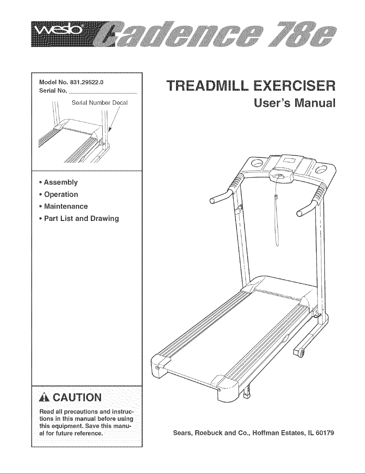
ModeJ No. 831.29522.0
SedaJ No.
SeriaUNumber DecaU
* Assembly
* Operation
Maintenance
Part List and Drawing
User's Manual
,_ CAUTmON
Read aH precautions and instruc-
tions in this manual before using
this equipment. Save this manu-
al for future reference.
Sears, Roebuck and Co., Hoffman Estates, IL 60179
Page 2
TABLE OF CONTENTS
iMPORTANT PRECAUTIONS ................................................................ 3
BEFORE YOU BEGIN ...................................................................... 5
ASSEMBLY .............................................................................. 6
OPERATHON AND ADJUSTMENT ............................................................. 9
HOW TO FOLD AND MOVE THE TREADMHLL ................................................. 11
MAHNTENANCE AND TROUBLESHOOTHNG ................................................... 12
CONDHTHONHNGGUHDELHNES .............................................................. 14
ORDERHNG REPLACEMENT PARTS ................................................. Back Cover
FULL 90 DAY WARRANTY .......................................................... Back Cover
Note: A PART iDENTiFiCATiON CHART, an EXPLODED DRAWING, and a PART LiST are attached in the
center of this manual
Page 3
iMPORTANT PRECAUTIONS
WARN raNG:Toreducetheriskofburns,f re,e ect.cshock,or njurytopersons,read
the following important precautions and information before operating the treadmill.
1. it is the responsibility of the owner to ensure your local Sears store or call 1-800-366-7278
that all users of this treadmill are adequateJy and order part number 146148, or see your
informed of all warnings and precautions, local electronics store.
2. Use the treadmill onJy as described.
Place the treadmill on a leveJ surface, with at
least eight feet of clearan se behind it and two
feet on each side. Do not pJace the treadmill
on any surface that bJocks air openings. To
protect the floor or carpet from damage,
ptace a mat under the treadmill.
4. Keep the treadmill indoors, away from mois-
ture and dust. Do not put the treadmill in a 14. Never move the walking belt while the power
garage or covered patio, or near water, is turned off. Do not operate the treadmill if
5. Do not operate the treadmill where aerosol
products are used or where oxygen is being
administered.
8. Keep children under the age of 12 and pets
away from the treadmill at aH times.
7. The treadmill shouJd not be used by persons
weighing more than 250 pounds.
8. Never allow more than one person on the
treadmill at a time.
9. Wear appropriate exercise clothing when
using the treadmill. Do not wear loose cloth-
ing that court become caught in the tread-
mill AtHetic support clothes are recommend-
ed for both men and women. Always wear
athletic shoes, Never use the treadmiiI with
bare feet, wearing only stockings, or in sam
dais.
10. When connecting the power cord (see page 9),
pJug the power cord into a surge suppressor
_not included] and pJug the surge suppressor
into a grounded circuit capable of carrying 15
or more stops. No other appJiance should be on
the same circuit. Do not use an extension cord.
12.
Failure to use a propedy functioning surge
suppressor could resuJt in damage to the con-
trol system of the treadmill if the controJ sys-
tem is damaged, the walking belt may change
speed, accelerate, or stop unexpectedJy,
which may result in a fall and serious injury.
13. Keep the power cord and the surge suppres=
sot away from heated surfaces.
the power cord or plug is damaged, or if the
treadmill is not working properly. (See page
12 if the treadmill is not working properly,)
15. Never start the treadmill while you are stand=
ing on the walking belt. Always hoJd the
handrails white using the treadmill
1& The treadmill is capabJe of high speeds.
Adjust the speed in small increments to
avoid sudden jumps in speed.
17. Never leave the treadmill unattended whiJe it is
running. Always remove the key and unplug
................... the treadmill is not in
use.
18. Do not attempt to raise, lower, or move the
treadmill until it is properly assembled. (See
ASSEMBLY on page 8. and HOW TO MOVE
THE TREADMILL on page 11.) You must be
abJe to safely lift 45 pounds (20 kg) in order
to raise, lower, or move the treadmill
19. Do not change the incline of the treadmill by
placing objects under the treadmill
20. When folding or moving the treadmill, make
sure that the storage latch is fully cJosed.
11. Use only a single-outlet surge suppressor that 21. inspect and properly tighten aH parts of the
meets aH of the specifications described on treadmHJ reguJariy.
page 9. To purchase a surge suppressor, see
Page 4
22.Neverdroporinsert any object into any authorized service representative. Servicing
opening, other than the procedures in this manual
should be performed by an authorized set-
23. DANGER: AIwayeunplugthepower v,cerepreeentat_veonly.
cord immediateJy after use, before cleaning
the treadmill, and before performing the 24. This treadmill is intended for in=home use
maintenance and adjustment procedures only. Do not use this treadmill in any como
described in this manual. Never remove the merciai, rental, or institutionaJ setting.
motor hood unJess instructed to do so by an
_ WARNING: Beforebeginningth_soranye.ercieeprogram,coneuJtyourphyaician.
This is especially important for persons over the age of 35 or persons with pre=e×isting health probo
lems. Read aH instructions before using. Sears assumes no responsibiJity for personal injury or
property damage sustained by or through the use of this product.
SAVE THESE iNSTRUCTiONS
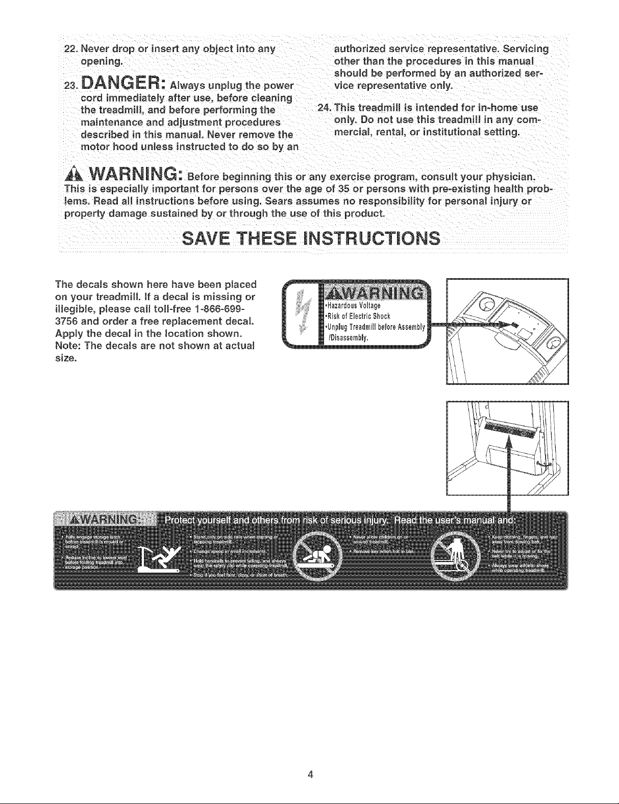
The decaJs shown here have been placed
on your treadmill, if a decal is missing or
illegible, ptease call toll-free 1-866=69g-
3756 and order a free repJacement decal
AppJy the decal in the location shown.
Note: The decaJs are not shown at actuaJ
size.
Page 5
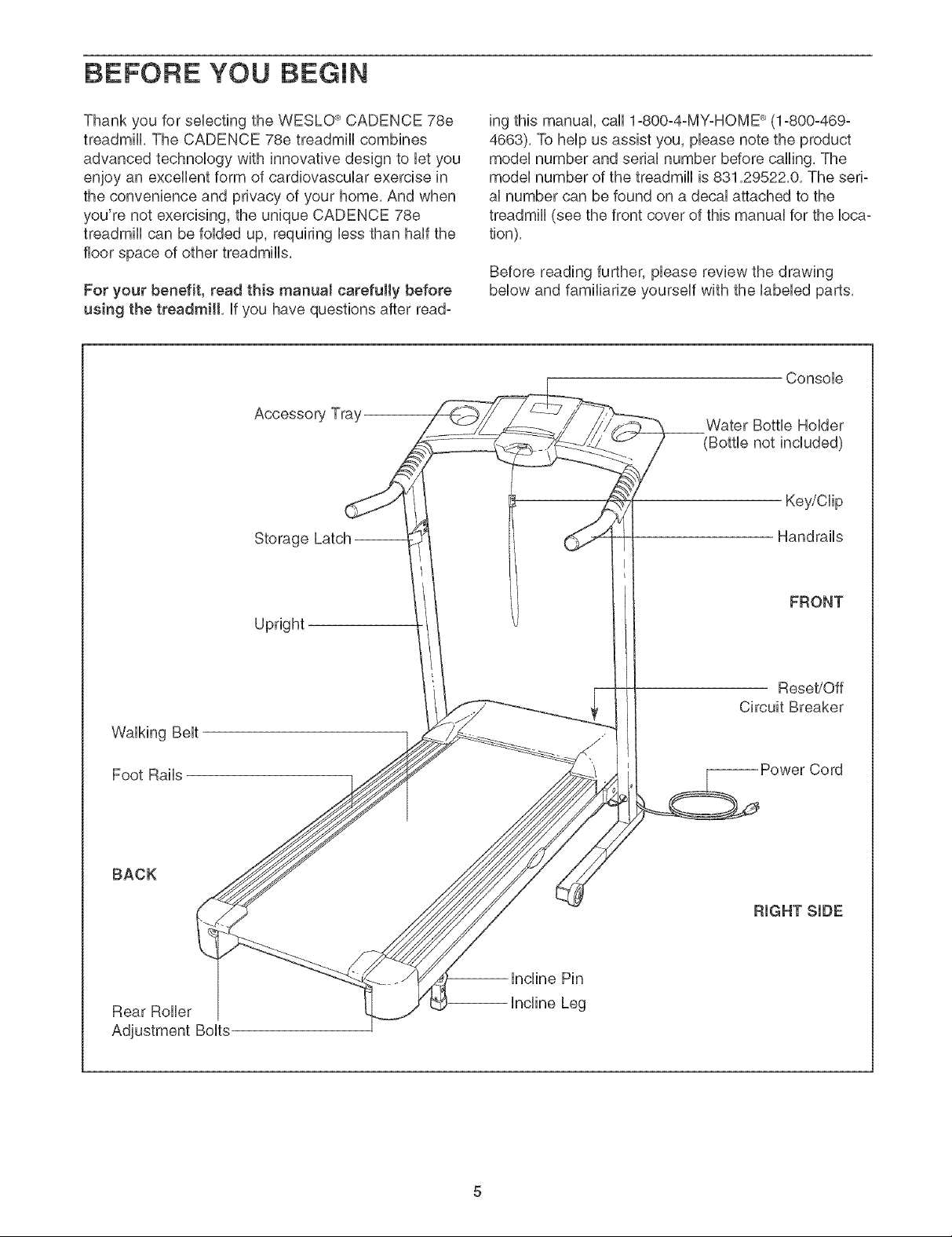
BEFORE YOU BEGmN
Thank you for selecting the WESLO ®CADENCE 78e
treadmill, The CADENCE 78e treadmill combines
advanced technology with innovative design to let you
enjoy an excellent form of cardiovascular exercise in
the convenience and privacy of your home, And when
you're not exercising, the unique CADENCE 78e
treadmill can be folded up, requiring less than half the
floor space of other treadmills,
For your benefit, read this rnanuaJ carefully before
using the treadmill, if you have questions after read-
Accessory Tray
Storage Latch-
ing this manual, call 1°800°4°MY-HOME ®(1-800-469-
4663), To help us assist you, please note the product
model number and serial number before calling, The
model number of the treadmill is 831,29522,0, The seri-
al number can be found on a decal attached to the
treadmill (see the front cover of this manual for the loca-
tion),
Before reading further, please review the drawing
below and familiarize yourself with the labeled parts,
Console
Water Bottle Holder
(Bottle not included)
Key/Clip
Handrails
Walking Belt
Foot Rails
BACK
Rear Roller
Adjustment Bolts
FRONT
Upright
Reset/Off
Circuit Breaker
RIGHT SIDE
-- Incline Pin
Incline Leg
Page 6
ASSEMBLY
Assembly requires two persons. Set the treadmill in a cleared area and remove all packing materials, Do not
dispose of the packing materials until assembly is compbted,
Note: The underside of the treadmill walking belt is coated with high-performance lubricant, During shipping, a
small amount of lubricant may be transferred to the top of the walking belt or the shipping carton, This is a nor-
mal condition and does not affect treadmill performance, if there is lubricant on top of the walking belt, simply
wipe off the lubricant with a soft cloth and a mild, non-abrasive cleaner,
Assembly requires the included allen wrenches _ and your own phillips screwdriver , wire
cutters _-_---_- and needtenose pliers
For help identifying the assembly hardware, see the PART IDENTIFICATION CHART attached in the cen-
ter of this manual, if a part is not in the parts bag, first check to see if it has been prs-assembbd, If a part is
missing, call toil-free 1-868-899-3758.
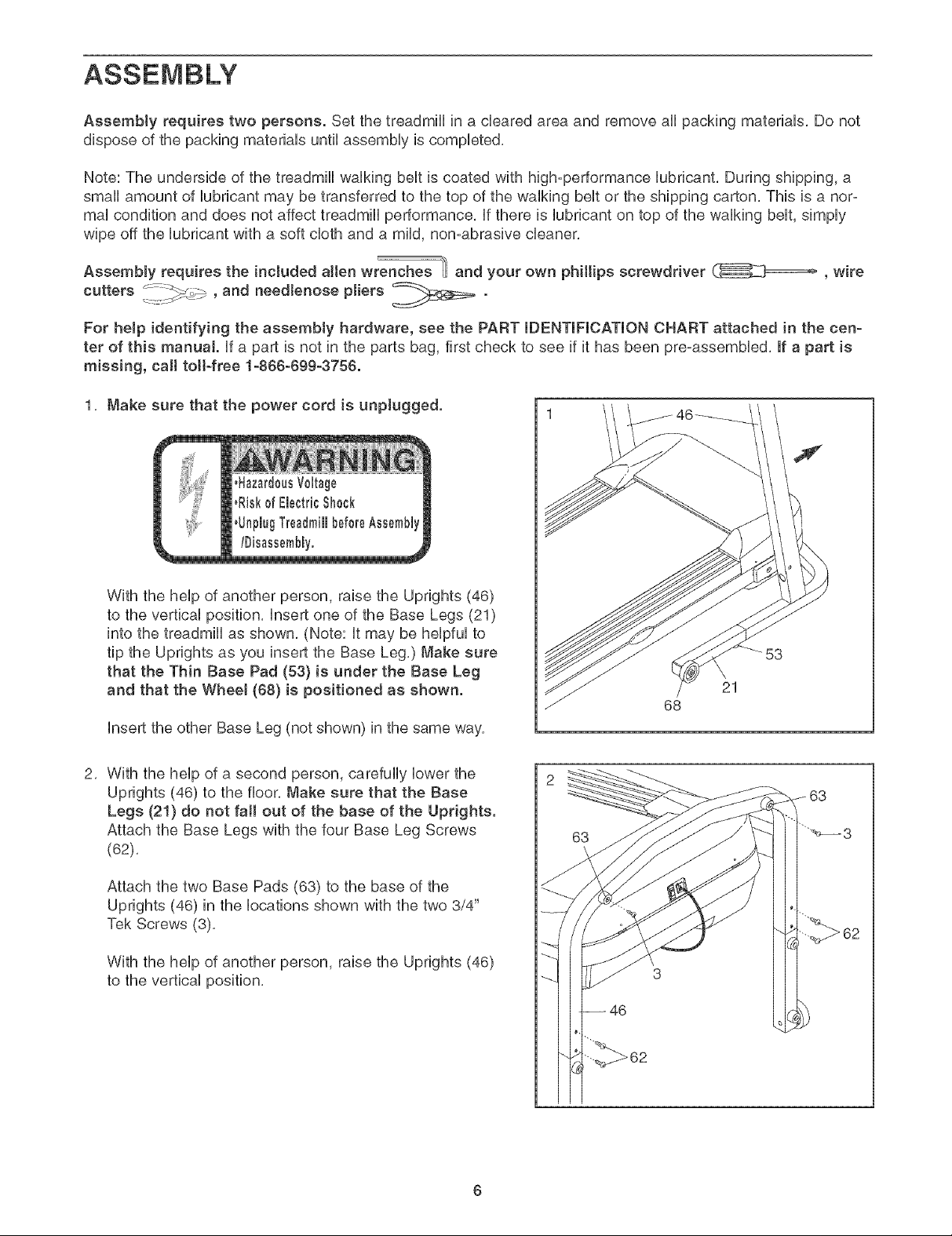
1, Make sure that the power cord is unplugged.
E
With the help of another person, raise the Uprights (46)
to the vertical position, insert one of the Base Legs (21)
into the treadmill as shown, (Note: it may be helpful to
tip the Uprights as you insert the Base Leg,) Make sure
that the Thin Base Pad (53) is under the Base Leg
and that the Wheel (88) is positioned as shown.
insert the other Base Leg (not shown) in the same way,
2, With the help of a second person, carefully lower the
Uprights (46) to the floor, Make sure that the Base
Legs (21} do not fall out of the base of the Uprights.
Attach the Base Legs with the four Base Leg Screws
(62),
Attach the two Base Pads (63) to the base of the
Uprights (46) in the locations shown with the two 3/4"
Tsk Screws (3),
With the help of another person, raise the Uprights (46)
to the vertical position,
21
68
62
Page 7

3, ifthereisa plastictieintherightUpright(46),remove
theplastictie,
3
HoldoneoftheHandrails(59)neartherightUpright(46)
asshown,inserttheWireHarness(60)upthroughthe
hobinthebottomoftheHandrailandoutoftheround
hobinthesideoftheHandrail,ifnecessary,use
needlenoseplierstopulltheWireHarnessoutof the
hob,BecarefutnottodamagetheWireHarness.
SettheHandrail(59)ontheupperendoftheright
Upright(46),Tightena HandrailBolt(55)intotheright
HandrailandtheUprightasshown,Becarefulnotto
pinchtheWireHarness(60).
AttachtheotherHandrail(59)asdescribedabove,Note:
Therearenowiresontheleftside,
4, SettheConsoleBase(52)ontheHandrails(59),Thread
four3/4"Screws(2)intotheHandrailsandtheConsole
Base,AfteryouhavestartedallfourScrews,tightenthe
Screwsuntiltheyaresnug;do notovertightenthe
Screws.Note:it maybehelpfultopressdownonthe
topoftheConsoleBaseabovetheHandrailsasyou
tightentheScrews,
inserttheWireHarness(60)throughthetwoindicated
plastictiesontheConsoleBase(52)andupthroughthe
hobintheConsoleBaseasshown,
55
59
59
60 \
46
46
52
60
59
Ties
2
5, Hold the Console (65) near the Console Base (52),
Touch the right Handrail (59) to discharge any static.
insert the Wire Harness (60) through the plastic tie
labeled C in the drawing at the right, Next, locate the
connector on the Wire Harness, Hug the Wire Harness
into the connector labeled A in the drawing at the right
and in the inset drawing, The connectors shoutd slide
together easily and snap into place, if they do not,
turn the connector on the Wire Harness and try again, IF
THE CONNECTOR IS NOT INSERTED PROPERLY,
THE CONSOLE MAY BE DAMAGED WHEN THE
POWER IS TURNED ON.
Pull any slack in the Wire Harness (60) through the plas-
tic tie labeled C, and securety tighten the plastic tie
around the Wire Harness. Cut off the end of the plastic
tie,
59
65
52
_ff
Page 8

6, Set the ConsoUe(65) in the ConsoUeBase (52), Make sure
that no wires are pinched, Insert as much of the Wire
Harness (60) as possiMe down into the hoUein the right
Handrail (59), Securely tighten the plastic tie nearest to
the right Handrail, Pull any excess Wire Harness
between the pUasticties tight and then tighten the other
pUastictie, Cut off the ends of the pUasticties,
Cover the Wire Harness (60) with the Wire Cover (11),
and route the Wire Harness out of the hoUein the side of
the Wire Cover, Attach the Wire Cover to the back of the
ConsoUe Base (52) with two 3/4" Screws (2), Do not over-
tighten the Screws.
Attach the ConsoUe (65) to the ConsoUe Base (52) with
five 3/4" Screws (2) in the Uocations shown, Note: There
shouJd not be a Screw in the hole indicated by the
arrow, Do not overtighten the Screws,
7, Attach the Storage Latch (48) to the left Upright (46)
with two 3/4" Screws (2),
Ties
No 65
Screw
52
2
2
59
8, Make sure that aH parts used in assembly are properly tightened before you use the treadmill Keep
the included allen wrench in a secure place, The allen wrench is used to adjust the walking belt (see page
13), To protect the floor or carpet, place a mat under the treadmill,
Page 9

OPERATION AND ADJUSTMENT
THE PRE-LUBRmCATED WALKmNG BELT
Your treadmHUfeatures a waUkingbeUtcoated with high°
performance Uubdcant, IMPORTANT: Never apply siF
icone spray or other substances to the walking
belt or the walking platform. Such substances will
deteriorate the walking belt and cause excessive
wear.
HOW TO PLUG IN THE POWER CORD
DANG ER: Improperconnect oo
of the equipmenbgrounding conductor can
result in an increased risk of electric shock.
Check with a qualified electrician or service-
man if you are in doubt as to whether the
product is properly grounded. Do not modify
the plug provided with the product--if it will
not fit the outlet, have a proper outlet
installed by a qualified eJectrician.
Your treadmill, like any other type of sophisticated
electronic equipment, can be seriously damaged by
sudden voltage changes in your home's power,
Voltage surges, spikes, and noise intederence can
result from weather conditions or from other appli-
ances being turned on or off, To decrease the pos-
sibility of your treadmill being damaged, aJways
use a surge suppressor with your treadmill (see
drawing 1 at the right}. To purchase a surge sup-
pressor, see your Jocal Sears store or call !-800-
366-7278 and order part number 148148, or see
your tocal electronics store.
of electric shock, This product is equipped with a cord
having an equipment-grounding conductor and a
grounding plug, Plug the power cord into a surge
suppressor, and plug the surge suppressor into an
appropriate outlet that is properly installed and
grounded in accordance with aH JocaJ codes and
ordinances. Important: The treadmill is not com-
patible with GFCm-equipped outlets.
This product is for use on a nominal 120-volt circuit,
and has a grounding plug that looks like the plug illus-
trated in drawing 1 below, A temporary adapter that
looks like the adapter illustrated in drawing 2 may be
used to connect the surge suppressor to a 2-pole
receptacle as shown in drawing 2 if a properly
grounded outlet is not available,
Grounded Outlet Box
_._ -- Surge Suppressor
_I _' Grounding Pin
I
Grounding Pin
_rounded Outlet Gr( unding Hug
2
_rounded Outlet Box
Adapter
Surge Suppressor
Use onJy a singJe-ouflet surge suppressor that is
UL 1449 tisted as a transient voJtage surge sup-
pressor (TVSS). The surge suppressor must have
a UL suppressed vottage rating of 400 voffs or Jess
and a minimum surge dissipation of 450 jouJes.
The surge suppressor must be electrically rated
for 120 volts AC and 15 amps. There must be a
monitoring Jight on the surge suppressor to indi-
cate whether it is functioning properly. Failure to
use a property functioning surge suppressor could
result in damage to the control system of the
treadmill. If the control system is damaged, the
waJking beff may change speed, accelerate, or
stop unexpectedly, which may resuff in a fall and
serious injury.
This product must be grounded, ff it should maF
function or break down, grounding provides a path of
least resistance for electric current to reduce the risk
The temporary adapter should be used only until a
properly grounded outlet (drawing 1) can be installed
by a qualified electrician,
The green-colored rigid ear, lug, or the like extending
from the adapter must be connected to a permanent
ground such as a properly grounded outlet box cover,
Whenever the adapter is used it must be held in place
by a metal screw, Some 2-poJe receptacle outJet
box covers are not grounded. Contact a qualified
electrician to determine if the outlet box cover is
grounded before using an adapter.
Page 10

STEP-BY-STEPCONSOLEOPERATION
Beforeoperatingtheconsole,makesurethatthe
powercordisproperlypluggedin(seepage9),
Next,steponto
thefootrailsof
thetreadmilk
Findthedip
attachedtothe
key,andslide
thedipontothe
waistbandof
yourclothes,
Then,insertthekeyfullyintotheconsob,Testthe
clipby carefullytakingafewstepsbackwarduntil
thekeyis putledfromtheconsote.If thekeyisnot
putledfromtheconsote,adjustthepositionofthe
clipas needed.Note:Topreventdamageto the
walkingplatform,alwayswearcleanshoeswhen
usingthetreadmill.
Followthestepsbelowtooperatetheconsole,
Insertthe keyfultyintotheconsote.
Whenthekeyisinserted,thedisplaywilllight,
Note:ifthereisa sheetof clearplasticonthe
faceoftheconsole,removetheplastic,
Adjustthespeedofthewatkingbelt.
Tostartthewalkingbelt,presstheDigitalSpeed
increasebutton,Thewalkingbeltwillbeginto
moveat1mph,Asyouexercise,changethe
speedofthewalkingbeltasdesiredbypressing
theDigitalSpeedbuttons,Note:Itmaytakea
momentforthewalkingbelttoreachtheselected
speedsetting,
Note:Theconsolecandisplaydistanceand
speedineithermilesorkilometers,Tochangethe
unitofmeasurement,firstholddowntheStopbut-
tonwhileinsertingthekeyintotheconsole,An
"E,"forEnglishmiles,oran"M,"formetricHome°
ters,wiiiappearinthedisplay,PresstheDigital
Speedincreasebuttontochangetheunitofmea-
surement,Then,presstheStopbutton,
Whenyouarefinishedexercising, remove the
key from the consote.
After removing the key, unplug the power cord,
Make sure to keep the key in a secure place,
Note: The first time the treadmill is used, observe
the alignment of the walking belt, and align the
walking belt if necessary (see page 13),
HOW TO CHANGE THE INCLINE
To vary the intensity of your exercise, the incline of the
treadmill can be changed, There are four incline lev-
els, Before changing the incline, remove the key
and unplug the power cord. Next, fold the treadmill
to the storage position (see HOW TO FOLD THE
TREADMILL FOR STORAGE on page 11),
To change the incline, first remove the incline pin from
one of the incline legs, Adjust the incline leg to the
desired height, and fully reinsert the incline pin, Make
sure that the incline pin is in the "locked" position
shown in the inset drawing, Adjust the other incline leg
in the same way, Make sure that both incline pins
are inserted from the direction shown.
Tostopthewalkingbelt,presstheStopbutton,
Fottowyour progresswith thedisplay.
Asyouexer-
cise,thedis=
playwill
showthe
elapsed
speedofthe
walkingbelt,
theapproximatenumberofcaloriesthatyouhave
burned,andthedistancethatyouhavewalkedor
runduringyourworkout,
Incline
Pin
CAUTION: Before using the treadmill, make sure
that both incJine legs are at the same height. Do
not use the treadmill with the incline pins
removed. After you have adjusted the incline legs,
lower the treadmill (see HOW TO LOWER THE
TREADMILL FOR USE on page 11),
10
Incline
Pin
Page 11

HOW TO FOLD AND MOVE THE TREADMILL
HOW TO FOLD THE TREADMmLL FOR STORAGE
Before foUdingthe treadmill unpUugthe power cord.
CAUTION: You must be abJe to safely tift 45 pounds (20
kg} in order to raise, lower or move the treadmill.
HoUdthe treadmHUwith your hands in the Uocationshown
by the arrow at the right. To decrease the possibility of
injury, bend your tegs and keep your back straight.
As you raise the treadmill, make sure to tilt with your
tegs rather than your back. Raise the treadmHUabout
haffway to the vertical position.
2,
Move your right hand to the position shown and hoUdthe
treadmHUfirmly, Using your left thumb, press the storage
latch to the left, Raise the treadmill until the storage latch
closes over the catch, Make sure that the storage tatch
is fully engaged over the catch.
To protect the floor or carpet from damage, ptace a
mat under the treadmill. Keep the treadmill out of
direct sunlight. Do not leave the treadmill in the stor-
age position in temperatures above 85° Fahrenheit.
t
HOW TO MOVE THE TREADMILL
Before moving the treadmill, convert the treadmill to the
storage position as described above, Make sure that the
frame is securely held by the storage tatch.
1. Hold the handrails, and place one foot against one of the
wheels.
2, Tilt the treadmill back until it rolls freely on the wheels,
Carefully move the treadmill to the desired location, To
reduce the risk of injury, use extreme caution while
moving the treadmill. Do not move the treadmill over
an uneven surface.
3, Place one foot against one of the wheels, and carefully
lower the treadmill to the storage position,
HOW TO LOWER THE TREADMILL FOR USE
1, See drawing 2 above, Hold the upper end of the treadmill with your right hand, Using your left thumb, press
the storage latch and hold it, Pivot the treadmill until the frame and the foot rails are past the storage latch,
2, See drawing 1, Hold the treadmill frame with both hands and lower it to the floor, Do not drop the treadmill
frame. CAUTION: To decrease the possibility of injury, bend your tegs and keep your back straight.
Handrails
Front
Wheels --_
"Base
11
Page 12

MAINTENANCE AND TROUBLESHOOTmNG
Most treadmill problems can be solved by following the simple steps below. Find the symptom that
applies, and follow the steps listed, ff further assistance is needed, call toll-free 1-800-4-MY-HOME ®
(1-800-469-4663}.
PROBLEM: The power does not turn on
SOLUTmON: a,
PROBLEM: The power turns off during use
SOLUTION: a. Check the reset/off circuit breaker located on the treadmill frame near the power cord (see 1. c.
Make sure that the power cord is plugged into a surge suppressor, and that the surge suppres-
sor is plugged into a properly grounded outlet (see page 9). Use only a single-outlet surge sup-
pressor that meets all of the specifications described on page 9. important: The treadmill is not
compatible with GFCI-equipped outlets.
b. After the power cord has been plugged in, make sure that the key is fully inserted into the console.
Check the reseVoff circuit breaker located on the
treadmill frame near the power cord. if the switch
protrudes as shown, the circuit breaker has
tripped. To reset the circuit breaker, wait for five
minutes and then press the switch back in.
above), if the circuit breaker has tripped, wait for five minutes and then press the switch back in.
b. Make sure that the power cord is plugged in. if the power cord is plugged in, unplug it, wait for
five minutes, and then plug it back in.
c. Remove the key from the console. Reinsert the key fully into the console.
d. if the treadmill still will not run, please call toll-free 1-800-4-MY-HOME _ (1-800-469-4663).
c
Tripped
Reset
PROBLEM: The displays of the console do not function propedy
SOLUTION: a,
Remove the key from the console and UNPLUG
THE POWER CORD. Next, remove the screws
from the hood and carefully remove the hood,
Locate the Reed Switch (76) and the Magnet (47)
on the left side of the Pulley (77), Turn the Pulley
until the Magnet is aligned with the Reed Switch,
Make sure that the gap between the Magnet and
the Reed Switch is about !/8". if necessary,
loosen the Screw (3), move the Reed Switch slight-
ly, and then retighten the Screw, Re-attach the
hood, and run the treadmill for a few minutes to
check for a correct speed reading,
Top
View
1/8"--
j77
3..
76_
12
Page 13

PROBLEM:Thewalkingbeltstowswhenwalkedon
SOLUTION:a, UseonUyasingb-outbtsurgesuppressorthatmeetsaHofthespecificationsdescribedonpage8,
b,
ff the waUkingbeUtis overtightened, treadmHUperfor-
mance may decrease and the waUking beUtmay
become damaged, Remove the key and UNPLUG
THE POWER CORD, Using the allen wrench, turn
both rear roller adjustment bouts countercbckwise,
1/4 of a turn, When the waUking beUtis properUy tight-
ened, you shouUd be abb to Hfteach side of the
waUking beUt2 to 3 inches off the waUking pUatform,
Be carefuUto keep the waUking beUtcentered, Hug in
the power cord, insert the key, and run the treadmill
for a few minutes, Repeat until the walking belt is
properly tightened,
c, If the walking belt still slows when walked on, please call toDfree 1-800-4-MY-HOME ®(1-800-
469-4663),
PROBLEM: The waJking belt is off-center or slips when walked on
Rear Roller
Adjustment Bolts
SOLUTION: a,
If the walking belt is off-center, first remove the key
and UNPLUG THE POWER CORD, If the walking
belt has shifted to the left, use the allen wrench to
turn the left rear roller bolt clockwise 1/2 of a turn; if
the walking belt has shifted to the right, turn the
bolt counterclockwise 1/2 of a turn, Be careful not to
overtighten the walking belt, Plug in the power cord,
insert the key, and run the treadmill for a few minutes.
Repeat until the walking belt is centered.
b,
if the walking belt slips when walked on, first remove
the key and UNPLUG THE POWER CORD, Using
the allen wrench, turn both rear roller bolts clockwise,
1/4 of a turn, When the walking belt is correctly tight-
ened, you should be able to lift each side of the walk-
ing belt 2 to 3 inches off the walking platform, Be
careful to keep the walking beff centered. Hug in
the power cord, insert the key, and carefully walk on
the treadmill for a few minutes, Repeat until the walk-
ing belt is properly tightened,
13
Page 14

CONDmONmNG GUmDEUNES
Aerobic Exercise
WARNING: Beforebeg noing
this or any exercise program, consult your
physician. This is especially important for
individuals over the age of 35 or individuaJs
with pre-existing heaJth probJeme.
The following guidelines wiii help you to plan your
exercise program. For more detailed exercise informa-
tion, obtain a reputable book or consult your physician.
EXERCmSE mNTENSmTY
Whether your goal is to burn fat or to strengthen your
cardiovascular system, the key to achieving the
desired results is to exercise with the proper intensity.
The proper intensity level can be found by using your
heart rate as a guide. The chart below shows recom-
mended heart rates for fat burning and aerobic exer-
cise.
HEART RATE TRAINING ZONES
AEROBIC 165 155 145 140 130 125 115
MAXFATBURN 145 138 130 125 113 110 103
FATBURN 125 120 115 110 105 95 90
Age 20 30 40 50 60 70 80
if your goal is to strengthen your cardiovascular sys-
tem, your exercise must be "aerobic." Aerobic exercise
is activity that requires large amounts of oxygen for
prolonged periods of time. This increases the demand
on the heart to pump blood to the muscles, and on the
lungs to oxygenate the blood. For aerobic exercise,
adjust the speed and incline of the treadmill until your
heart rate is near the highest number in your training
zone,
HOW TO MEASURE YOUR HEART RATE
To measure your
heart rate, stop exer-
cising and place two
fingers on your wrist
as shown. Take a six-
second heartbeat
count, and multiply
the result by ten to
find your heart rate.
(A six-second count is used because your heart rate
drops quickly when you stop exercising.) if your heart
rate is too high or too low, adjust the speed or incline
of the treadmill accordingly.
WORKOUT GUIDELINES
To find the proper heart rate for you, first find your age
at the bottom of the chart (ages are rounded off to the
nearest ten years). Next, find the three numbers
above your age. The three numbers are your "training
zone." The lower two numbers are recommended
heart rates for fat burning; the highest number is the
recommended heart rate for aerobic exercise.
Fat Burning
To burn fat effectively, you must exercise at a relatively
low intensity level for a sustained period of time.
During the first few minutes of exercise, your body
uses easily accessible carbohydrate calories for ener-
gy. Only after the first few minutes does your body
begin to use stored fat calories for energy, if your goal
is to burn fat, adjust the speed and incline of the tread-
mill until your heart rate is near one of the lower two
numbers in your training zone.
A welProunded workout includes the following three
A Warm-up
Start each workout with 5 to 10 minutes of stretching
and light exercise, A proper warm-up increases your
body temperature, heart rate, and circulation in prepa-
ration for exercise,
Training Zone Exercise
After warming up, increase the intensity of your exer-
cise until your pulse is in your training zone for 20 to
60 minutes. (During the first few weeks of your exer-
cise program, do not keep your pulse in your training
zone for longer than 20 minutes.) Breathe regularly
and deeply as you exercise--never hold your breath.
14
Page 15

ACoot-down EXERCmSEFREQUENCY
Finisheachworkoutwith5to 10minutesofstretching
tocooUdown,Thiswillincreasetheflexibilityofyour
muscbsandwHUheUptopreventpost-exerciseprobbms,
SUGGESTEDSTRETCHES
Thecorrectformforseveralbasicstretchesisshownattheright,Moveslowlyasyoustretch--neverbounce,
1.ToeTouchStretch
Standwithyourkneesbentslightlyandslowlybendforwardfrom
yourhips,Allowyourbackandshoulderstorelaxasyoureach
downtowardyourtoesasfaraspossible,Holdfor15counts,
thenrelax,Repeat3 times,Stretches:Hamstrings,backofknees
andback,
2.HamstringStretch
Sitwithonelegextended,Bringthesoboftheoppositefoot
towardyouandrestitagainsttheinnerthighofyourextended
leg,Reachtowardyourtoesasfaraspossible,Holdfor15
counts,thenrelax,Repeat3 timesforeachleg,Stretches:
Hamstrings,lowerbackandgroin,
Tomaintainor improveyourcondition,compbtethree
workoutseachweek,withatbastonedayofrest
betweenworkouts,Aftera fewmonths,youmaycom-
pbteuptofiveworkoutseachweekifdesired,Thekey
tosuccessistomakeexerciseareguUarandenjoyabb
partofyoureverydaylife,
2
3.Calf/AchillesStretch
Withoneleginfrontoftheother,reachforwardandplaceyour
handsagainsta wall,Keepyourbacklegstraightandyourback
footfiatonthefloor,Bendyourfrontleg,banforwardandmove
yourhipstowardthewall,Holdfor15counts,thenrelax,Repeat
3timesforeachleg,Tocausefurtherstretchingoftheachilles
tendons,bendyourbacklegaswell,Stretches:Calves,achilles
tendonsandankles,
4.QuaddcepsStretch
Withonehandagainsta wallforbalance,reachbackandgrasp
onefootwithyourotherhand,Bringyourheelasdosetoyour
buttocksaspossible,Holdfor15counts,thenrelax,Repeat3
timesforeachleg,Stretches:Quadrieepsandhipmuscles,
3
P
15
Page 16

PART LiST--Model No, 831.29522.0 Ro3o5c
Key No. Qty. Description
1 1
2 14
3 13
4 5
5 1
6 1
7 1
8 1
9 2
10 2
11 1
12 2
13 1
14 2
15 4
16 1
17 2
18 2
19 1
2O 1
21 2
22 1
23 1
24 1
25 1
26 1
27 2
28 1
29 2
30 1
31 1
32 6
33 1
34 2
35 1
36 1
37 2
38 3
39 1
4O 4
41 1
42 4
43 4
44 2
45 2
46 1
47 1
48 1
Motor Hood
3/4" Screw
3/4" Tek Screw
8" CaMe Tie
CaMe Tie
CUampScrew
CaMe Tie CUamp
Left Foot Rail
Front UsoUator
Front Hatform Screw
Wire Cover
incline Leg Washer
Catch
BeUtGuide
BeUtGuide Screw
Reed Switch CHp
Spacer Screw
Hood Anchor
Motor
Base Leg
Motor Tension BoUt
Motor Tension Washer
Motor Star Washer
Motor Tension Nut
Motor Pivot BoUt
Frame Spacer
Power Cord Grommet
Upright Star Washer
Power Cord
Controller
Ebctronb Screw
Choke
Hood Bracket
Ebctronbs Bracket
Reset/Off Circuit Breaker
Base Leg Endcap
Roller Adjustment Washer
Front Roller Adjustment BoUt
Hastb Fastener
Motor BeUt
Handrail BoUt
UsoUatorScrew
U-Nut
Handrail Endcap
Upright Base
Magnet
Storage Latch
Key No. Qty. Description
49
5O
51
52
53
54
55
56
57
58
59
60
61
62
63
64
65
66
67
68
69
7O
71
72
73
74
75
76
77
78
79
8O
81
82
83
84
85
86
87
#
#
#
#
Note: "#" indicates a non-illustrated part,
if a part is missing, call toll-free !-866-699-3756.
Specifications are subject to change without notice,
1
1
1
1
2
1
2
1
4
1
2
1
2
4
4
1
1
2
2
2
2
2
1
1
1
1
1
1
1
2
1
2
2
2
1
1
1
2
1
1
1
1
1
Left Endcap
Ground Wire
Key/Clip
Console Base
Thin Base Pad
Battery Cover
Handrail Bolt
Speed Potentiometer
Hood Screw
Upright Grommet
Handrail
Wire Harness
Wheel Nut
Base Leg Screw
Base Pad
Allen Wrench
Console
Upright Fiat Washer
Wheel Bolt
Wheel
Rear Platform Screw
Frame Bolt
Motor Pivot Nut
Walking Belt
Walking Board
Large Warning Decal
Reed Switch/Sensor Wire
Drive Roller/Pulley
Isolator
Frame
Incline Pin
Incline Leg
Incline Leg Cap
Right Endcap
Right Foot Rail
Rear Roller
Rear Roller Adjustment Bolt
Warning Decal
4" White Wire, M/F
4" Blue Wire, 2F
4" Black Wire, 2F
User's Manual
Page 17

PART iDENTiFiCATiON CHART
Remove this chart and use it to identify smatl parts during assembly. Save
this chart and the EXPLODED DRAWiNG/PART LiST for future reference.
Base Leg Screw (62)-4
3/4" Screw (2)-12 3/4" Tek Screw (3)-2
Handrail BoUt(55)-2
Page 18

EXPLODED DRAWINGwModel No. 831.29522.0 no3osc
33
s]
57 32_
76 19
27 3
22 ,
23
54
59
45
59
?
45
39
7O
7O
38
86
6O
84
86
66 6t
Page 19

Your Home
For repair- in your home - of all major brand appliances, lawn and garden equipment,
or heating and cooling systems, no matter who made it, no matter who sold it!
For the replacement parts, accessories, and user's manuals that you need to do-it-yourself.
For Sears professional installation of home appliances
and items like garage door openers and water heaters.
1-800-4-MY-HOME ® Anytime, day or night
(1-800-469-4663) (U.S.A. and Canada)
www.sears.com www.sears.ca
Our Home
For repair of carry-in products like vacuums, lawn equipment,
and electronics, call or go on-line for the location of your nearest
Sears Parts and Repair Center.
1-800-488-1222 Anytime, day or night (U.S.A. only)
www.sears.com
To purchase a protection agreement (U.S.A.)
or maintenance agreement (Canada) on a product serviced by Sears:
......................... 1-800-827-6655 (U.S.A.) 1-800-361-6665 (Canada)
Para pedir servicio de reparaci6n a domicilio, y para ordenar piezas:
; 1-888-SU-HOGAR sM (1-888-784-6427)
® Registered Trademark / TMTrademark / SMService Mark of Sears, Roebuck and Co.
@ Marca Registrada / Marca de F&brica / Marce de Servicie de Sears, Roebuck end Co.
TM SM
f
FULL 90 DAY WARRANTY
For 90 days from the date of purchase, if failure occurs due to defect in materiaU or workmanship in this
Sears TreadmHUExerciser, contact the nearest Sears Service Center throughout the United States and
Sears wHUrepair or repUacethe TreadmHUExerciser, free of charge,
This warranty does not appUywhen the TreadmHUExerciser is used commercially or for rentaUpurposes,
This warranty gives you specific legal rights, and you may also have other rights which vary from state
to state,
Sears, Roebuck and Co., Dept. 817WA, Hoffman Estates, IL 60179
4J
Part No, 221532 R0305C Printed in USA © 2005 Sears, Roebuck and Co,