

Page 1
WFE 20D
Betriebsanleitung - Mode d’emploi - Gebruiksaanwijzing - Istruzioni per l’uso - Operating
Instructions - Instruktionsbok - Manual de uso - Betjeningsvejledning - Manual do utilizador Käyttöohjeet - √‰ËÁ›Â˜ §ÂÈÙÔ˘ÚÁ›·˜ - Kullan∂m k∂lavuzu -
Návod k pouÏití - Instrukcja obs∏ugi Üzemeltetési utasítás - Návod na pouÏívanie - Navodila za uporabo - Kasutusjuhend Naudojimo instrukcija - Lieto‰anas instrukcija
Page 2

S
E
DK
GB
Table of contents Page
1. Caution! 14
2. Description 14
Technical data 14
3. Commissioning 14
4. Operating the unit 15
5. Breakdown assistance 16
6. Maintenance, working information 16
7. Replacement parts 16
8. Accessories 16
9. Shipment 16
10. Appendix 16
Innehållsförteckning Sidan
1. Observera! 17
2. Beskrivning 17
Tekniska data 17
3. Idrifttagande 17
4. Användning 18
5. Felsökning 18
6. Underhåll, arbetsbeskrivning 19
7. Reservdelar 19
8. Tillbehör 19
9. I leveransen ingår 19
10. Bilaga 19
Indice Página
1. Atención! 20
2. Descripción 20
Datos técnicos 20
3. Puesta en servicio 20
4. Manejo del aparato 21
5. Eliminación de fallos 22
6. Mantenimiento, indicación para eltrabajo 22
7. Repuestos 23
8. Accesorios 23
9. Volumen de suministro 23
10. Apéndice 23
Indholdsfortegnelse Side
1. Forsigtig! 24
2. Beskrivelse 24
Tekniske Data 24
3. Ibrugtagning 24
4. Betjening af apparatet 25
5. Fejlafhjælpning 25
6. Vedligehold, Arbejdsanvisning 26
7. Reservedele 26
8. Tilbehør 26
9. Leveringsomfang 26
10. Bilag 26
D
F
NL
I
Inhaltsverzeichnis Seite
1. Achtung! 1
2. Beschreibung 1
Technische Daten 1
3. Inbetriebnahme 1
4. Bedienungs des Gerätes 2
5. Problem und Lösung 3
6. Wartung, Arbeitshinweise 3
7. Ersatzteile 3
8. Zubehör 3
9. Lieferumfang 3
10. Anhang 3
Table des matières Page
1. Attention! 4
2. Description 4
Caractéristiques techniques 4
3. Mise en service 4
4. Commande de l’appareil 5
5. Remèdes aux dérangements 6
6. Entretien, consigne de travail 6
7. Pièces de rechange 7
8. Accessoires 7
9. Ensemble de la livraison 7
10. Annexe 7
Inhoud Pagina
1. Attentie! 8
2. Beschrijving 8
Technische gegevens 8
3. Ingebruikneming 8
4. Bediening van het toestel 9
5. Opheffing van storingen 10
6. Onderhoud, advies 10
7. Onderdelen 10
8. Toebehoren 10
9. Omvang van de levering 10
10. Aanhangsel 10
Indice Pagina
1. Attenzione! 11
2. Descrizione 11
Caratteristiche tecniche 11
3. Messa in funzione 11
4. Impiego dell’apparecchio 12
5. Eliminazione di guasti 13
6. Manutenzione, note sul lavoro 13
7. Parti di ricambio 13
8. Accessori 13
9. Volume di fornitura 13
10. Appendice 13
Page 3
WFE 20D
Page 4
DK
P
FIN
E
GB
I
S
NL
F
D
1
2
8
9
10
7
3D9R802
6 5
4
3
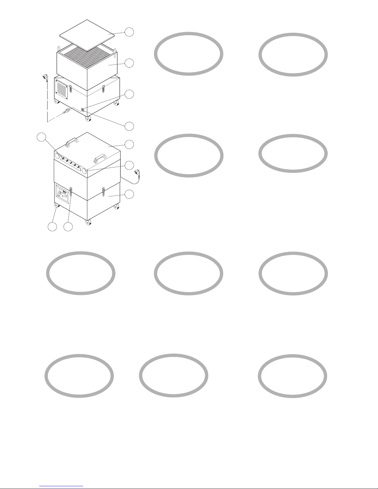
1. Aansluitkast vacuüm
2. Turbinekast
3. Vacuümaansluiting pijpsysteem DN40
4. Vacuümaansluiting steeknippel
5. Spanslot
6. Transportrollen
7. Compactfilter
8. Voorfilter
9. Netaansluiting
10.Zekering
1. Boîtier de raccordement au vide
2. Carter de la turbine
3. Raccordement au vide système
de tuyauterie DN40
4. Raccordement au vide nipple
enfichable
5. Tendeur d’assemblage
6. Roulettes de transport
7. Filtre compact
8. Premier filtre
9. Raccordement au secteur
10.Fusible
1. Anschlussgehäuse Vacuum
2. Turbinengehäuse
3. Vacuumanschluss Rohrsystem DN40
4. Vacuumanschluss Stecknippel
5. Spannschloss
6. Transportrollen
7. Kompaktfilter
8. Vorfilter
9. Netzanschluss
10.Sicherung
1. Vacuum connection housing
2. Turbine housing
3. Vacuum connection for DN40 hose
system
4. Nipple for push-on vacuum
connection
5. Locking clamp
6. Transport rollers
7. Compact filter
8. Pre-filter
9. Mains connection
10. Fuse
1. Carter di attacco per vuoto
2. Carter della turbina
3. Attacco per vuoto sistema a tubi
DN40
4. Attacco per vuoto nipplo spinato
5. Tenditore a vite
6. Rotelle di trasporto
7. Filtro compatto
8. Prefiltro
9. Attacco di alimentazione
10.Fusibile
1. Anslutningsdel vakuum
2. Turbinhus
3. Vakuumanslutning rörsystem DN40
4. Vakuumanslutning insticksnippel
5. Spännlås
6. Transporthjul
7. Kompaktfilter
8. Förfilter
9. Nätanslutning
10. Säkring
1. Liitäntäkotelo vakuumi
2. Turbiinikotelo
3. Vakuumiliitäntä putkijärjestelmä
DN40
4. Vakuumiliitäntä pistenippa
5. Kiristyslukko
6. Kuljetusrullat
7. Kompaktisuodatin
8. Esisuodatin
9. Verkkoliitäntä
10.Sulake
1. Caja de conexión para vacío
2. Caja de turbina
3. Toma de vacío sistema de tubos
DN40
4. Toma de vacío boquilla de
empalme
5. Cierre tensor
6. Ruedas de transporte
7. Filtro compacto
8. Filtro previo
9. Conexión a la red
10.Fusible
1. Forbindelseshus, vakuum
2. Turbinehus
3. Vakuumtilslutning rørsystem
DN40
4. Vakuumtilslutning stiknippel
5. Bardunstrammer
6. Transportruller
7. Kompaktfilter
8. Forfilter
9. Nettilslutning
10.Sikring
1. Carcaça de conexão do vácuo
2. Carcaça da turbina
3. Conexão de vácuo do sistema de
tubagem DN40
4. Conexão de vácuo do niple de encaixe
5. Fechadura tensão
6. Rolos de transporte
7. Filtro compacto
8. Filtro prévio
9. Conexão da rede
10. Fusível
Page 5

P
11. Interruptor de rede eléctrica
12. Interface RS232
13. Display
14. Tecla "UP"
15. Tecla "DOWN"
16. Tecla "TIMER"
17. Indicador nível do filtro
E
11. Interruptor de alimentación
12. Interfaz RS232
13. Display
14. Tecla "UP"
15. Tecla "DOWN"
16. Tecla "TIMER"
17. Indicador de estado del filtro
I
11. Interruttore di rete
12. Interfaccia RS232
13. Display
14. Tasto "UP"
15. Tasto "DOWN"
16. Tasto "TIMER"
17. Indicatore di livello del filtro
D
11. Netzschalter
12. RS232 Schnittstelle
13. Display
14. "UP" Taste
15. "DOWN" Taste
16. "TIMER" Taste
17. Filterzustandsanzeige
11
17
4D9R809
12 13
16
14
15
S
NL
DK
GB
F
11. Netafbryder
12. RS232 Grænseflade
13. Display
14. "UP" Knap
15. "DOWN" Knap
16. "TIMER" Knap
17. Filtertilstandsviser
11. Mains switch
12. RS232 Interface
13. Display
14. "UP" button
15. "DOWN" button
16. "TIMER" button
17. Filter status display
11. Interrupteur d’alimentation
12. Interface RS232
13. Display
14. Touche "UP"
15. Touche "DOWN"
16. Touche "TIMER"
17. Affichage de l’état du filtre
11. Nätströmbrytare
12. RS232 Gränssnitt
13. Display
14. "UP"-knapp
15. "DOWN"-knapp
16. "TIMER"-knapp
17. Filterindikator
11. Netschakelaar
12. RS232 interface
13. Display
14. "UP" toets
15. "DOWN" toets
16. "TIMER" toets
17. Filter toestandsindicator
Page 6

14
Thank you for placing your trust in our company by purchasing the WELLER WFE 20D soldering fumes extractor.
Production was based on stringent quality requirements
which guarantee the perfect operation of the device.
1. Caution!
Please read these Operating Instructions and the attached
safety information carefully prior to initial operation. Failure
to observe the safety regulations results in a risk to life and
limb.
The manufacturer shall not be liable for damage resulting
from misuse of the machine or unauthorised alterations.
The WELLER WFE 20D soldering fumes extractor corresponds to the EC Declaration of Conformity in accordance
with the basic safety requirements of Directives
2004/108/EC and 2006/95/EC + 2004/42/EC.
2. Description
The WELLER Soldering Fume Extraction Device WFE 20D has
a powerful maintenance-free turbine, making is perfectly
suited to continuous operation in industry. The unit was
designed for direct extraction at the soldering iron and is
suitable for surface extraction.
A digital electronics system allows simple and convenient
operation of the available functions. The vacuum created by
the turbine is controlled in standard mode (mode 0) electronically to the preset value of 8.000 Pa. This value can be
changed individually in mode 2.
If low extraction power is sufficient, the control setpoint can
be reduced in mode 2. If mode 2 has been set, the unit must
be switched over to the desired operating mode to prevent
an inadvertent change of the setpoint value. In addition, the
turbine speed can be changed manually in speed-controlled
mode 1 in the range 20% - 100%.
For connection to the pipe system DN40, a max. of 2 vacuum connections (3) are available. The pipe system can be
arranged individually by positioning the vacuum connections
(plug-in nipples) for the soldering irons (max. 20) as
required. Alternatively, 5 vacuum connections are provided
directly on the unit for soldering iron fume extraction.
The standard composition of the installed 3-stage filter (fine
dust filter, HEPA filter and wide-band gas filter) is specially
adapted to soldering fumes. With the use of the type-tested
HEPA filters in Class H13, the separation rate of the filter set
upon delivery is 99.95% as per EN 1822 with a particle size
of 0.12 m. These figures are only achieved with the use of
original parts. A required filter change is indicated by a display of a differential pressure measurement on the unit.
Using a standard RS232 interface, all of the unit's functions
can be operated and remotely controlled. An operating hours
code and operating hours specification widen the scope of
the unit's functions.
3. Commissioning
Direct interconnection of the FE soldering bits
The WELLER WFE 20D soldering fume extractor is fitted out
for the direct interconnection of a maximum of 5 WELLER FE
soldering bits. To connect up the vacuum hose, first remove
the sealing lid and then push the hose directly onto the pushon nipple (4). The FE soldering bit unit uses a vacuum hose
that is 2.5 m long. If the soldering stations are further away
(up to 5 m), a DN17 extension hose can be used (this can be
obtained as an accessory). Push-on nipples must be fitted to
the end of the DN17 hose and the unit.
Indirect interconnection via a DN40 hose system
(accessory)
The WELLER WFE 20D is interconnected to the vacuum hose
system via a flexible fume extraction hose NW44 for indirect
operation. In this case the 5 push-on nipples (4) remain
sealed and the sealing plug (3) for the hose system has to be
removed. In order to connect up the hose system for the FE
English
Technical data
Dimensions L X W X H: 450 mm X 450 mm X 695 mm
Weight: 45 kg
Voltage: 230 V/50 Hz
Electrical power rating: 630 VA
Vacuum (controlled): 8,000 Pa
Maximum quantity supplie: 100 m3/h
Noise emission level: 51 dB(A)
Filter: Stage 1 Pre-filter F5
Stage 2; 3 Class H13 high efficiency sub-micron particle air filter
(99.95% particles up to approx. 0.12 µm)
combined with a wide-band gas filter
(50% AKF, 50% Puratex)
Page 7

English
soldering bits, a Ø 7.0 mm hole must be tapped in the
required position, the push-on nipple must be screwed into it
and the vacuum hose from the FE soldering bits must then
be pushed onto the nipple.
Electrical connection
The nominal voltage must be checked against the details
given on the nameplate prior to commissioning. If the mains
voltage is correct, connect the WFE 20D to the mains supply
(9) and switch on the equipment using the mains switch (11).
A green LED (filter is OK) indicates that the unit is running.
The percentage details for the turbine rotational speed are
shown on the display (13).
4. Operating the unit
Operating mode
The unit is in mode 0 when it leaves the factory. Vacuum is
controlled to 8.000 Pa. This is the ideal setting for direct
extraction with WELLER FE soldering irons. Changes are not
possible in mode 0. However, if you require a different vacuum for control, this can be changed in setting mode 2 from
5.000 Pa to 8.000 Pa in steps of 100 Pa. (Display of 50 – 100)
Switching operating mode
Hold down the UP and DOWN (14/15) buttons simultaneously when switching on. The currently set operating mode is
shown in the display (ex works setting -0-). If the TIMER button (16) is additionally pressed, the unit can be switched to
mode 1 or mode 2. When the UP and DOWN button is
released, the unit starts in the set operating mode. In operating mode 1, the turbine is speed-controlled. The turbine
speed and thus the extraction power can be adjusted steplessly between 20% - 100% using the UP/DOWN button
(14/15). Setting mode 2 should only be used for modifying
the control setpoint. The unit should then be switched to
operating mode 0. Operating mode 0 now uses the modified
control setpoint.
Filter checks
The filter status display (17) indicates when (through filter
differential pressure measurement) the permitted degree of
contamination has been exceeded and when the filter insert
has to be changed. The red filter control LED will illuminate
and the unit will be switched off. The sub-micron particle filter and wide-band gas filter are fitted one on the other, so
that they can be changed together as a compact filter.
The fine dust filter (8) (filter mat), is the pre-filter level of the
compact filter (7) and therefore has to be changed more
often. The pre-filter mat change is satisfactory, if the red LED
(17) is no longer illuminated when the equipment is switched
back on.
Displaying the filter operating hours
Press the TIMER button (16) and the current filter operating
hours will be displayed (display X 10). Flashing display. The
operating hours display must be manually reset after a filter
change. Keep the TIMER button (16) pressed down until the
display is reset to 000.
Filter operating hours default setting
The filter operating hours can be entered as a default setting
for better handling of the filter change intervals. When the
default operating hours setting has expired, the unit will be
switched off and “filter change required” will be indicated by
a flashing display (13) and the illumination of the red LED
(17).
Press the TIMER button (16) to enter the default operating
hours setting. The current filter operating hours will now
flash on the display. Press the UP/DOWN buttons (14/15)
simultaneously whilst the display is flashing. Release
UP/DOWN buttons (14/15) and now use them to enter the
default operating hours.
RS232 Interface
It is possible to control the WFE 20D via a PC using the integrated standard RS232 interface (12). This enables the full
range of system functions to be used or remotely controlled.
Remote control
The remote control (which is available as an accessory) can
be operated via the RS232 interface (12). The unit’s main
functions can be transmitted using this remote control.
●
Switching the unit On/Off
●
Speed setting in mode - 1 -
●
Filter status display
Knowing that the WFE 20D can be operated via a remote
control is helpful when selecting the site for the unit.
Decommissioning
Attention!
A high concentration of pollutants will result in the
active carbon heating up. The equipment should be run
for several minutes in a pollutant free state before being
switched off in order to prevent unwanted heating up.
15
Page 8

16
7. Replacement parts
See Exploded Page 66 for replacement parts for standard
installations
Fine dust filter F7
Wide-band gas filter (50% AKF, 50% Puratex) without an H13
particulate air filter
8. Accessories
0058735909 Remote control
Pipe system DN40 (Page 67)
9. Shipment
1 WFE 20D including filter set
1 connecting cable
1 Operating manual
1 Safety information
10. Appendix
Accessories for DN40 pipe system
Subject to technical alterations and amendments!
See the updated operating instructions at
www.weller-tools.com.
English
6. Maintenance, working information
Various fluxes, flux components as well as different dust particles in the extracted air can significantly reduce the filter’s
working life.
The sub-micron particles in the air increase when soldering
or welding on varnished insulated wire. The standardised F5
filter mat should be exchanged for a class F7 fine dust filter
for these or similar applications.
A compact filter with a greater quantity of active carbon
(without particulate air filter stage) should be used when
extracting adhesive vapour.
Filter changes
The mains plug must always be pulled out of the mains
socket before any maintenance work is undertaken. To
change the filter you must first open the locking clamps (5)
between the turbine housing (2) and the filter housing (1)
and then lift off the filter housing. Pull the vacuum hose off
of the compact filter. The compact filter (7) and the fine dust
filter (8) can be removed using the carrying straps. The fine
dust filter is laid inside the compact filter (see exploded
drawing 66).
Attention!
The minimum pressure hose must be reconnect ed correctly and the holding latches must be turned
downwards when replacing the filter.
Dirty filter are classified as hazardous waste.
5. Breakdown assistance
Malfunction Cause Solution
Extraction power missing Pipe system leaking Reseal the pipe system
Filter is dirty Change the filter
Vacuum is too low Increase the extraction power
(mode 1 only)
WFE 20D is not running Thermally switched off Leave the WFE 20D to cool down
Switch on again after approx. 3 hours.
Filter display is red Filter is full Change the filter
Unit is not running Minimum pressure hose Reconnect the hose to the filter
was not replaced after
the filter change
Sub-micron particle Pre-filter has not been Use a pre-filter
becoming dirty to quickly used Fit an F7 filter
Use a preliminary separator if the
proportion of solid matter is high.
Page 9

66
Explo Drawing
Page 10

67
Pipe system DN 40
36
5 36 329 99
5 36 324 99
5 36 343 99
5 36 338 99
5 36 320 99
5 36 343 99
5 36 326 99
36 338 99
5 36 322 99
5 36 323 99
5 344 99
5 36 319 99
5 36 316 99
3D9R811
266
182
163
170
157
7
7
5
5 36 321 99
80 2000 180
57
118
266
Page 11

68
Circuit Diagram
4D3R812
1
EC - Hoch-
druckgebläse
M
~
2
5
6
ws
3
4
sw
br
rt
gn
ge
br
58735901
sw
ws
4D3R812
X1
C1
R4
R5
R6
R3
R1
R2
N1
D1D2
S2
S1
S3
T3 T2 T1
A3 A2 A1
D1
Netzanschluß
230V
Netz-
schalter
T3,15A
Page 12

www.weller-tools.com
Weller®is a registered Trademark and registered Design of Apex Tool Group, LLC.
© 2011, Apex Tool Group, LLC.
T005 57 147 04 / 07.2011
T005 57 147 03 / 06.2008
GERMANY
Weller Tools GmbH
Carl-Benz-Str. 2
74354 Besigheim
Phone: +49 (0) 7143 580-0
Fax: +49 (0) 7143) 580-108
FRANCE
Apex Tool Group S.A.S.
25 av. Maurice Chevalier BP 46
77832 Ozoir-la-Ferrière, Cedex
Phone:+33 (0) 1 60.18.55.40
Fax: +33 (0) 1 64.40.33.05
GREAT BRITAIN
Apex Tool UK Limited
4
th
Floor Pennine House
Washington, Tyne & Wear
NE37 1LY
Phone: +44 (0191) 419 7700
Fax: +44 (0191) 417 9421
ITALY
Apex Tool S.r.I.
Viale Europa 80
20090 Cusago (MI)
Phone: +39 (02) 9033101
Fax: +39 (02) 90394231
SWITZERLAND
Apex Tool Switzerland Sàrl
Rue de la Roselière 8
1400 Yverdon-les-Bains
Phone: +41 (024) 426 12 06
Fax: +41 (024) 425 09 77
AUSTRALIA
Apex Tools
P.O. Box 366
519 Nurigong Street
Albury, N. S. W. 2640
Phone: +61 (2) 6058-0300
CANADA
Apex Tools - Canada
164 Innnisfil street
Barrie Ontario
Canada L4N 3E7
Phone: +1 (905) 455 5200
USA
Apex Tool Group, LLC.
14600 York Rd. Suite A
Sparks, MD 21152
Phone: +1 (800) 688-8949
Fax.: +1 (800) 234-0472
CHINA
Apex Tools
18
th
Floor, Yu An Building
738 Dongfang Road
Pudong, Shanghai
200122 China
Phone: +57 (2) 691 0900
 Loading...