


WX 1, WX 2, WXD 2, WXA 2
DE Originalbetriebsanleitung
GB Translation of the original instructions
ES Traducción del manual original
FR Traduction de la notice originale
IT Traduzione delle istruzioni originali
PT Tradução do manual original
NL Vertaling van de oorspronkelijke
gebruiksaanwijzing
SV Översättning av bruksanvisning
i original
DK Oversættelse af den originale
brugsanvisning
FI Alkuperäisten ohjeiden
käännös
GR Μετάφραση του πρωτοτύπου
των οδηγιών χρήσης
TR Orijinal işletme talimatı çevirisi
CZ Překlad původního návodu
k používání
PL Tłumaczeniem instrukcji oryginalnej
HU Eredeti használati utasítás fordítása
SK Preklad pôvodného návodu
na použitie
SL Prevod izvirnih navodil
EE Algupärase kasutusjuhendi tõlge
LV Instrukciju tulkojumam no
oriģinālvalodas
LT Originalios instrukcijos vertimas
BG Превод на оригиналната
инструкция
RO Traducere a instructiunilor
originale
HR Prijevod originalnih uputa
RU Оригинальное руководство по
эксплуатации

Deutsch
English
Español
Français
Italiano
Portugues
Nederlands
Svenska
Dansk
Suomi
Ελληνικα
Türkçe
Český
Polski
Magyar
Slovensky
Slovenščina
Eesti
Latviski
Lietuviškai
Български
Român
Hrvatski
Pусский
Technische Daten | Sicherheitshinweise | Menüführung |
Pege und Wartung | Garantie
Technical Data | Safety information | Menu navigation |
Care and maintenance | Warranty
Datos Técnicos | Advertencias de seguridad | Guía de menú |
Cuidado y mantenimiento | Garantía
Caractéristiques Techniques | Consignes de sécurité | Menu |
Entretien et maintenance | Garantie
Dati Tecnici | Avvertenze per la sicurezza | Guida a menu |
Cura e manutenzione | Garanzia
Características Técnicas | Indicações de segurança |
Menu de navegação | Conservação e manutenção | Garantia
Technische Gegevens | Veiligheidsinstructies | Menunavigatie |
Onderhouden | Garantie
Tekniska Data | Säkerhetsanvisningar | Menyer |
Skötsel och underhåll | Garanti
Tekniske Data | Sikkerhedsanvisninger | Menustruktur |
Pleje og vedligeholdelse | Garanti
Tekniset Arvot | Turvallisuusohjeet | Valikko-ohjaus |
Aseman hoito ja huolto | Takuu
Τεχνικά στοιχεία | Υποδείξεις ασφαλείας | Καθοδήγηση· μενού |
Φροντίδα και συντήρηση της συσκευής | Εγγύηση
Teknik Veriler | Güvenlik uyarıları | Menü yönlendirmesi |
Temizliği ve bakımı | Garanti
Technické údaje | Bezpečnostní pokyny | Struktura menu |
Údržba a servisní práce ohledně | Záruka
Dane Techniczne | Wskazówki bezpieczeństwa | Menu | Pielęgnacja i
konserwacja urządzenia | Gwarancja
Műszaki Adatok | Biztonsági utasítások | Menükezelés |
Ápolás és karbantartás | Garancia
Technické údaje | Bezpečnostné pokyny | Navigácia v menu |
Ošetrovanie a údržba | Záruka
Tehnični Podatki | Varnostna navodila | Menijska struktura |
Nega in vzdrževanje | Garancija
Tehnilised Andmed | Ohutusjuhised | Menüü juhtimine |
Hooldamine ja teenindamine | Garantii
Tehniskie dati | Drošības norādes | Izvēlnes vadība |
Apkope un kopšana | Garantija
Techniniai duomenys | Saugos taisyklės | Meniu valdymas | Įprastinė
ir techninė priežiūra | Garantija
Технически данни | Инструкции за безопасна работа |
Навигация в менюто | Обслужване и поддържане | Гаранция
Date tehnice | Indicaţii de securitate | Ghidarea în meniu |
Îngrijirea şi întreţinerea curentă | Garanţia pentru produs
Tehnički podatci | Sigurnosna upozorenja | Navigiranje kroz izbornik
Njega i servisiranje | Jamstvo
Технические характеристики
Управление с помощью меню | Уход и обслуживание | Гарантия
| Рекомендации по технике безопасности |
|
19
30
41
52
63
74
85
96
107
118
129
140
151
162
173
184
195
206
217
228
239
250
261
272
DEGBESFRITPTNLSVDKFIGRCZ TRPL
HU
SKSLEELTLVBG
RO
HRRU

Zu Ihrer Sicherheit
Wir danken Ihnen für das mit dem Kauf dieses Geräts erwiesene Vertrauen.
Bei der Fertigung wurden strengste Qualitätsanforderungen zugrunde gelegt, die eine einwandfreie
Funktion des Gerätes sicherstellen.
Lesen Sie diese Anleitung und die
beiliegenden Sicherheitshinweise vor
Inbetriebnahme und bevor Sie mit dem
Gerät arbeiten vollständig durch.
Bewahren Sie diese Anleitung so auf, dass sie für
alle Benutzer zugänglich ist.
Sicherheitshinweise
Aus Sicherheitsgründen dürfen
Kinder und Jugendliche unter
16 Jahren sowie Personen, die
nicht mit dieser Betriebsanleitung vertraut sind, das Gerät
nicht benutzen. Kinder sollten
beaufsichtigt werden, um sicherzustellen, dass sie nicht mit dem
Gerät spielen.
Warnung! Stromschlag
Durch unsachgemäßes Anschließen des Steuergeräts besteht Verletzungsgefahr
durch Stromschlag und das Gerät kann beschädigt werden.
Lesen Sie die beiliegenden Sicherheitshinweise, die Sicherheitshinweise dieser Betriebsanlei-
tung sowie die Anleitung Ihres Steuergeräts vor Inbetriebnahme des Steuergeräts vollständig
durch und beachten Sie die darin gegebenen Vorsichtsmaßnahmen.
Schließen Sie nur WELLER WX-Werkzeuge an.
Verwendung Sie niemals den USB-Port als Spannungsversorgung für Fremdgeräte.
Bei defektem Gerät können aktive Leiter frei liegen oder der Schutzleiter ohne Funktion sein.
Reparaturen müssen durch von Weller ausgebildete Personen erfolgen.
Ist die Anschlussleitung des Elektrowerkzeugs beschädigt, muss sie durch eine speziell
vorgerichtete Anschlussleitung ersetzt werden, die über die Kundendienstorganisation
erhältlich ist.
Diese Anleitung enthält wichtige Informationen,
um das Gerät sicher und sachgerecht in Betrieb
zu nehmen, zu bedienen, zu warten und einfache
Störungen selbst zu beseitigen.
Das Gerät wurde entsprechend dem heutigen Stand
der Technik und den anerkannten sicherheitstechnischen Regeln hergestellt.
Trotzdem besteht die Gefahr von Personenund Sachschäden, wenn Sie die Sicherheitshinweise
im beiliegenden Sicherheitsheft sowie die Warnhinweise in dieser Anleitung nicht beachten.
Dieses Gerät ist nicht dafür
bestimmt, durch Personen
(einschließlich Kinder) mit eingeschränkten physischen, sensorischen oder geistigen Fähigkeiten oder mangels Erfahrung und/
oder mangels Wissen benutzt zu
werden.
DE
Warnung! Verbrennungsgefahr
Beim Betrieb des Steuergeräts besteht Verbrennungsgefahr am Lötwerkzeug. Werk-
zeuge können nach dem Ausschalten noch längere Zeit heiß sein.
Legen Sie das Lötwerkzeug bei Nichtgebrauch immer in der Sicherheitsablage ab.
Schließen Sie Vakuum und Heißluft nur an den dafür vorgesehenen Anschlüssen an.
Den Heißluftkolben nicht auf Personen oder brennbare Gegenstände richten.
19

Zu Ihrer Sicherheit
DE
Bestimmungsgemäße Verwendung
Versorgungseinheit für WELLER WX-Werkzeuge.
Verwenden Sie die Lötstation / Entlötstation /
Heißluftstation ausschließlich gemäß dem in
der Betriebsanleitung angegebenen Zweck zum
Löten und Entlöten unter den hier angegebenen
Bedingungen.
Brennbare Gase und Flüssigkeiten
dürfen nicht abgesaugt werden.
Das Gerät darf nur mit korrekt eingesetzen und dafür vorgesehenen
Filterkartuschen betrieben werden.
Ersetzen Sie volle Filterkartuschen.
Benutzergruppen
Aufgrund unterschiedlich hoher Risiken und Gefahrenpotentiale dürfen einige Arbeitsschritte nur von
geschulten Fachkräften ausgeführt werden.
Arbeitsschritt Benutzergruppe
Vorgabe der Lötparameter Fachpersonal mit technischer Ausbildung
Auswechseln von elektrischen Ersatzteilen Elektrofachkraft
Vorgabe von Wartungsintervallen Sicherheitsfachkraft
Bedienen
Filterwechsel
Bedienen
Filterwechsel
Auswechseln von elektrischen Ersatzteilen
Gerät nur in Innenräumen verwenden. Vor Feuchtigkeit und direkter Sonneneinstrahlung schützen.
Der bestimmungsgemäße Gebrauch schließt auch
ein, dass
Sie diese Anleitung beachten,
Sie alle weiteren Begleitunterlagen beachten,
Sie die nationalen Unfallverhütungsvorschriften
am Einsatzort beachten.
Für eigenmächtig vorgenommene Veränderungen am Gerät wird vom Hersteller keine Haftung
übernommen.
Laien
Technische Auszubildende unter Anleitung und Aufsicht einer ausgebildeten Fachkraft
Gerät in Betrieb nehmen
Achtung!
Beachten Sie die jeweiligen Betriebsanleitungen
der angeschlossenen Geräte.
Nehmen Sie das Gerät wie im Kapitel „Inbetriebnahme“ beschrieben in Betrieb.
Überprüfen Sie, ob die Netzspannung
mit der Angabe auf dem Typenschild
übereinstimmt.
Gerät nur ausgeschaltet an die Steckdose anschließen.
20
Nach dem Einschalten des Gerätes führt der Mikroprozessor einen Selbsttest durch und liest die im
Werkzeug gespeicherten Parameterwerte aus.
Solltemperatur und Festtemperaturen sind auf
dem Werkzeug gespeichert. Temperatur-Istwert
steigt bis zur Solltemperatur (= Lötwerkzeug wird
aufgeheizt).
WXA 2: Stickstoff N2 vermindert die Oxidation und
das Flussmittel bleibt länger aktiv. Wir empfehlen
Stickstoff N2, der in Stahlaschen im Handel erhältlich ist. Die Flasche muss mit einem Druckminderer 0-10 bar ausgerüstet sein.

Zu Ihrer Sicherheit
Löten und Entlöten
Führen Sie die Lötarbeiten gemäß der Betriebsanleitung Ihres angeschlossenen Lötwerkzeuges
durch.
Behandlung der Lötspitzen
Benetzen Sie beim ersten Aufheizen die selektive
und verzinnbare Lötspitze mit Lot. Dies entfernt
lagerbedingte Oxydschichten und Unreinheiten
der Lötspitze.
Achten Sie bei Lötpausen und vor dem Ablegen
des Lötkolbens darauf, dass die Lötspitze gut
verzinnt ist.
Verwenden Sie keine zu aggressiven Flussmittel.
Achten Sie immer auf den ordnungsgemäßen
Sitz der Lötspitzen.
Wählen Sie die Arbeitstemperatur so niedrig wie
möglich.
Wählen Sie die für die Anwendung größtmögliche
Lötspitzenform
Daumenregel: ca. so groß wie das Lötpad.
Sorgen Sie für einen großächigen Wärmeüber-
gang zwischen Lötspitze und Lötstelle, indem Sie
die Lötspitze gut verzinnen.
Schalten Sie bei längeren Arbeitspausen das
Lötsystem aus oder verwenden Sie die Weller
Funktion zur Temperaturabsenkung bei
Nichtgebrauch.
Benetzen Sie die Spitze mit Lot, bevor Sie den
Lötkolben für längere Zeit ablegen.
Geben Sie das Lot direkt auf die Lötstelle, nicht
auf die Lötspitze.
Wechseln Sie die Lötspitzen mit dem dazugehöri-
gen Werkzeug.
Üben Sie keine mechanische Kraft auf die
Lötspitze aus.
Hinweis
Die Steuergeräte wurden für eine mittlere
Lötspitzengröße justiert. Abweichungen durch
Spitzenwechsel oder der Verwendung von
anderen Spitzenformen können entstehen.
WX 2, WXD 2, WXA 2: Überlastabschaltung (255 W)
Um die Überlastung einer WX Station zu vermeiden, wird bei einer Werkzeugleistung beider Kanäle von mehr als 255 Watt ein Kanal automatisch
deaktiviert (Auto-Off).
Außerdem kommt es zu einer Überlastungabschaltung wenn folgende Werkzeugkombinationen
angeschlossen werden:, z. B.
- 2 WXHP 120 Heizplatten
- Eine WXHP 120 Heizplatte und ein Entlötkolben
WXDP 120 oder WXDV 120
DE
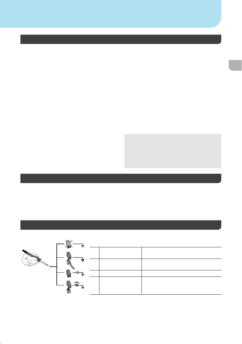
Potentialausgleich
a
b
c
d
Durch unterschiedliche Schaltung der 3,5 mm Schaltklinkenbuchse
sind 4 Varianten möglich:
a Hart geerdet Ohne Stecker (Auslieferungszustand).
b Potentialausgleich Mit Stecker, Ausgleichsleitung am
Mittelkontakt.
c Potentialfrei Mit Stecker
d Weich geerdet Mit Stecker und eingelötetem Wider-
stand. Erdung über den gewählten
Widerstand
21

Zu Ihrer Sicherheit
Firmware update durchführen
DE
Hinweis
Während das Firmware update läuft, darf die
Station nicht ausgeschalten werden.
Pege und Wartung
Warnung!
Vor allen Arbeiten am Gerät Stecker
aus der Steckdose ziehen.
Bedienpanel mit geeignetem Reinigungstuch bei
Verunreinigung reinigen.
Nicht verwendete Schnittstellen mit Verschlusskappen verschließen.
Warnung! Verbrennungsgefahr
Lötspitzenwechsel nur in kaltem
Zustand
Saugdüsenwechsel und Reinigung
nur in heißem Zustand mit
passendem Werkzeug
Heißluftdüsenwechsel nur mit
passendem Werkzeug
Zinnsammelbehälter nur in kaltem
Zustand reinigen oder wechseln
1. Lötstation ausschalten.
2. Speicherstick in die USB-Schnittstelle einstecken.
3. Lötstation einschalten.
Firmware update wird automatisch durchgeführt.
Falls Sie eine aktuellere Firmware bereits auf
Ihrer Station installiert haben, wird diese nicht
verändert.
Filterwechsel
Hauptlter für Vakuum regelmäßig auf Verschmutzung kontrollieren und gegebenenfalls erneuern.
Warnung!
Zerstörung der Vakuumeinheit durch Arbeiten ohne
Filter.
Kontrollieren Sie bevor Sie mit Lötarbeiten
beginnen, ob ein Hauptlter eingelegt ist!
Verschmutzte Filter müssen als Sondermüll
behandelt werden.
Entsorgen Sie ausgetauschte Geräteteile, Filter oder alte Geräte gemäß den Vorschriften
Ihres Landes.
Tragen Sie geeignete Schutzausrüstung.
Warnung!
Nur original WELLER-Ersatzteile
verwenden.
Garantie
Die Mängelansprüche des Käufers verjähren in
einem Jahr ab Ablieferung an ihn. Dies gilt nicht
für Rückgriffsansprüche des Käufers nach §§ 478,
479 BGB.
Aus einer von uns abgegebenen Garantie haften
wir nur, wenn die Beschaffenheits- oder Haltbarkeitsgarantie von uns schriftlich und unter
Verwendung des Begriffs „Garantie“ abgegeben
worden ist.
22
Die Garantie verfällt bei unsachgemäßem Gebrauch
und wenn von unqualizierten Personen Eingriffe
vorgenommen wurden.
Technische Änderungen vorbehalten!
Bitte informieren Sie sich unter
www.weller-tools.com.

Parametermenü
Standby Temperatur Menüaufruf Tool-Parameter
Die Lötwerkzeuge haben eine Nutzungserkennung
(Sensor) im Griff, welche bei Nichtbenutzung des
Lötwerkzeugs den Abkühlvorgang automatisch
einleitet.
Nach einer Temperaturabschaltung wird automa-
tisch die Standby Temperatur eingestellt.
Standby Zeit (Temperaturabschaltung) Menüaufruf Tool-Parameter
Bei Nichtgebrauch des Lötwerkzeugs wird die
Temperatur nach Ablauf der eingestellten Standby
Zeit auf Standby Temperatur abgesenkt.
Drücken der Bedien-Taste beendet diesen Stand-
by Zustand. Der im Werkzeug integrierte Sensor
erkennt die Zustandsänderung und deaktiviert den
Standby Zustand, sobald das Werkzeug bewegt
wird.
Option Beschreibung
OFF Standby Zeit ist ausgeschaltet
(Werkseinstellung)
1-99 min Standby Zeit , individuell einstellbar
1-999 min - - -
AUTO-OFF Zeit (Automatische Abschaltzeit) Menüaufruf Tool-Parameter
Bei Nichtgebrauch des Lötwerkzeugs wird nach
Ablauf der AUTO-OFF Zeit die Heizung des Lötwerkzeuges abgeschaltet.
Die Temperaturabschaltung wird unabhängig von
der eingestellten Standby-Funktion ausgeführt.
Die Isttemperatur wird blinkend angezeigt und
dient als Restwärmeanzeige. Im Display erscheint
„AUTO-OFF“.
Option Beschreibung
OFF AUTO-OFF Funktion ist ausgeschal-
tet (Werkseinstellung)
1-999 min AUTO-OFF Zeit, individuell einstell-
bar.
Empndlichkeit Menüaufruf Tool-Parameter
Option Beschreibung
Low unempndlich – reagiert auf starke (lange) Bewegung
Normal standard (Werkseinstellung)
High empndlich - reagiert auf leichte (kurze) Bewegung
- - - wird vom Werkzeug nicht unterstützt
DE
Max. Heißluftdauer WXHAP 200 Menüaufruf Tool-Parameter
Einschaltzeit für Heißluftkolben (WXHAP 200)
begrenzen. Die Einschaltzeit für den Heißluftstrom
des WXHAP 200 kann in 1er-Schritten von 0 bis
300 s begrenzt werden. Die eingestellte Zeit ist
dann für alle 2 Kanäle gleich. Werkseinstellung
ist 0 s („OFF“), d.h. der Luftstrom wird aktiviert,
solange der Taster am Heißluftkolben oder der
optionale Fußschalter gedrückt ist.
Option Beschreibung
OFF Keine Dauer deniert (Werksein-
stellung)
1-300 s Individuell einstellbar
Offset (Temperatur-Offset) Menüaufruf Tool-Parameter
Die tatsächliche Lötspitzentemperatur kann durch
Eingabe eines Temperatur-Offsets um ± 40 °C
(± 72 °F) angepasst werden.
23

Parametermenü
Regelverhalten Menüaufruf Tool-Parameter
DE
Die Funktion bestimmt das Aufheizverhalten des
Lötwerkzeuges zum Erreichen der eingestellten
Werkzeugtemperatur.
Tastenverriegelung WXHAP 200 Menüaufruf Tool-Parameter
Mit dieser Funktion kann das werkseitig eingestellte Tastenverhalten des WXHAP 200 Kolbens
verändert werden.
Prozessfenster Menüaufruf Tool-Parameter
Der im Prozessfenster eingestellte Temperaturbereich bestimmt das Signalverhalten des potentialfreien Schaltausgangs.
Hinweis
Bei Werkzeugen mit LED Ringlicht (z. B.
WXDP 120) bestimmt das Prozessfenster das
Leuchtverhalten des LED Ringlichts.
Option Beschreibung
Standard Angepasstes (mittleres) Aufheizen
(Werkseinstellung)
Sanft Langsames Aufheizen
Aggressiv Schnelles Aufheizen
Option Beschreibung
ON Der WXHAP 200 wird mit dem ersten
Tastendruck ein- und mit einem weiteren Tastendruck ausgeschaltet.
OFF –
Konstantes Leuchten bedeutet das Erreichen der
vorgewählten Temperatur bzw. die Temperatur ist
innerhalb des vorgegebenen Prozessfensters.
Blinken signalisiert, dass das System aufheizt
bzw. die Temperatur außerhalb des Prozessfensters ist.
Sprache Menüaufruf Stationsparameter
CHN
中文
DEN Dansk
ENG English
ESP Español
FIN Suomi
FRA Français
GER Deutsch
HUN Magyar
ITA Italiano
POR Português
RUS Pусский
SWE Svenska
TUR Türkçe
JPN
日本語
POL Polski
한국말
KOR
CZE Český
Temperaturversion °C/°F (Temperatureinheiten) Menüaufruf Stationsparameter
Option Beschreibung
° C Celsius
° F Fahrenheit
24

Parametermenü
Passwort (Verriegelungsfunktion) Menüaufruf Stationsparameter
Nach Einschalten der Verriegelung sind an der
Lötstation nur noch die Festtemperatur-Tasten
bedienbar. Alle anderen Einstellungen können bis
zur Entriegelung nicht mehr verstellt werden.
Hinweis
Soll es wirklich nur einen Temperaturwert zur
Auswahl geben, müssen die Bedien-Tasten
(Festtemperatur- Tasten) auf den gleichen
Temperaturwert eingestellt werden.
Lötstation verriegeln:
Den gewünschten dreistelligen Verriegelungscode
(zwischen 001-999) mit dem Dreh-Klick-Rad
einstellen.
Die Verriegelung ist aktiv (im Display ist ein
Schloss zu sehen).
Lötstation entriegeln
1. Parametermenü aufrufen. Ist die Verriegelung
aktiv, öffnet sich automatisch der Passwort-
Menü-Punkt. Im Display erscheinen drei Sterne
(***).
2. Den dreistelligen Verriegelungscode mittels
Dreh-Klick-Rad einstellen.
3. Code mit der Eingabe-Taste bestätigen.
Code vergessen?
Wenden Sie sich bitte an
unseren Kunden Service:
technical-service@weller-tools.com
Vakuum Vorlauf (nur WXD 2) Menüaufruf Stationsparameter
Um ein vorzeitiges Starten der Pumpe zu ver-
hindern oder um eine denierte Vorwärmzeit der
Lötstelle zu gewährleisten, kann eine Einschaltverzögerung eingestellt werden
Option Beschreibung
0 sec OFF: Vakuum Vorlauf Funktion ist
1-10
sec
ausgeschaltet (Werkseinstellung)
ON: Vakuum Vorlauf Zeit, individuell
einstellbar
Vakuum Nachlauf (nur WXD 2) Menüaufruf Stationsparameter
Um das Verstopfen des Entlötkolbens zu verhindern, kann eine Vakuum Nachlauf-Zeit eingestellt
werden.
Option Beschreibung
0 sec OFF: Vakuum Nachlauf Funktion ist
1-10
sec
ausgeschaltet (Werkseinstellung)
ON: Vakuum Nachlauf Zeit, individuell
einstellbar
DE
Tastentöne ein/aus Menüaufruf Stationsparameter
Option Beschreibung
ON eingeschaltet
OFF ausgeschaltet
Roboterausgang Menüaufruf Stationsparameter
Der Roboterausgang bendet sich auf der Rückseite des Geräts.
WX 1: OFF - ON - ZeroSmog - Stop&Go
WX 2 / WXD 2: OFF- Links - Rechts - Links & Rechts - ZeroSmog - Stop&Go
25

Parametermenü
Option Beschreibung
DE
Lin
ks
Re
chts
Lin
ks & rechtsBeide Werkzeugkanäle
ZeroSmog Der hintere potentialfreie Schaltausgang wird bei Benutzung eines Tools geschlossen.
Stop&Go Die hintere RS 232 Schnittstelle wird zum Ansteuern eines optionalen Optoadapters
Fußschalter (nur WXD 2 und WXA 2) Menüaufruf Stationsparameter
Um ein vorzeitiges Starten der Pumpe zu ver-
hindern oder um eine denierte Vorwärmzeit der
Lötstelle zu gewährleisten, kann eine Einschaltverzögerung eingestellt werden
Option Beschreibung
OFF OFF: Fußschalter ist deaktiviert
ON ON: Fußschalter ist aktiviert. Die vordere RS232 Schnittstelle kann zum Anschluß des
Link
er Werkzeugkanal (Werkseinstellung)
Re
chter Werkzeugkanal
Über einen optionalen Adapter (WX HUB) können bestimmte Zero Smog angeschlossen werden. Die rückseitige RS 232 Schnittstelle ist weiterhin funktionsfähig.
Schaltausgang ist offen
gesteckt ist.
verwendet um über einen Lichtleiter eine KHE/KHP schalten zu können.
Bei Benutzung eines Tools wird der Ausgang aktiviert. Zusätzlich wird der potentialfreie
Schaltausgang geschlossen. Ausgang ist aus bei Standby, AUTO-OFF, OFF oder wenn
kein Werkzeug gesteckt ist.
Hinweis
Ist die Arbeitstemperatur für den Roboter erreicht, dann wird im Display ein
– ok – angezeigt. nicht bei Zero Smog + Stop&Go
optionellen WX Fußschalters verwendet werden. Dieser entspricht bei Entlötwerkzeugen (nur WXD 2) oder Heißluftwerkzeugen (nur WXA 2) der Funktion des Fingerschalters. Die Funktion des Fingerschalters bleibt parallel erhalten.
bei Standby, AUTO-OFF, OFFo
der wenn kein Werkzeug
Zusatzgeräte anschließen
Beachten Sie die Übersichtabbildungen.
Zusatzgeräte anschließen
Zusatzgeräte können entweder an der Schnittstelle an der Frontseite und/oder an der Schnittstelle
auf der Rückseite der Lötstation angeschlossen
werden.
Die Lötstation erkennt automatisch, welches Zusatzgerät angeschlossen ist. Die Lötstation zeigt
die Schnittstelle vorn, oder die Schnittstelle hinten,
das Symbol oder den Namen des angeschlossenen Zusatzgeräts an.
26
Parameter der Zusatzgeräte einstellen
1. Zusatzgerät über Zusatzgerät-Taste
(vorn/hinten) auswählen.
Einstellbarer Parameter erscheint im Display
(z. B. Drehzahl).
2. Den gewünschten Wert mit dem Dreh-Klick-Rad
einstellen.
3. Wert mit der Eingabe-Taste bestätigen

Technische Daten
Lötstation Lötstation Entlötstation Heißluftstation
WX 1 WX 2 WXD 2 WXA 2
Abmessungen LxBxH 170 x 151 x 130 mm
Gewicht (ca.) in kg ca. 3,2 kg ca. 3,2 kg ca. 3,8 kg ca. 3,8 kg
Spannung 230 V, 50 Hz / 120 V, 60 Hz / 100 V 50/60 Hz
Leistung 200 W 200 W (255 W) 200 W (255 W) 200 W (255 W)
Schutzklasse I, Gehäuse antistatisch
Sicherung T2 A (230 V)
Temperaturbereich
werkzeugabhängig
Temperaturgenauigkeit ± 9 °C
Temperaturstabilität ± 2 °C
Potentialausgleichsbuchse Über 3,5 mm Schaltklinkenbuchse an der Geräterückseite.
Display 255 x 128 dots / Hintergrundbeleuchtung
Schnittstelle Das Steuergerät ist mit einer frontseitigen USB-Schnittstelle für Firm-
Druckluft - Eingangsdruck
Luftverbrauch l/min - 35 l / min
Druckluftanschluss - Druckluft-
Max. Luftmenge l/min
(werkzeugabhängig)
6,69 x 5,94 x 5,12 inch
III, Lötwerkzeug
T4 A (120 V)
Celsius: 100 - 450°C (550°C)
Fahrenheit: 200 - 850°F (999°F)
Regelbarer Temperaturbereich ist werkzeugabhängig.
± 17 °F
± 4 °F
ware update, Parametrierung, Monitoring und Daten Logging (mittels
WX-Monitor Software) ausgerüstet.
400 - 600 kPA
(58-87 psi)
ölfreie, trockene
Druckluft
max Unterdruck
75 kPA (10,9 psi)
schlauch
Außendurch-
messer 6 mm
(0,24“)
- ca. 0-18 l/ min
Eingangsdruck
400 - 600 kPA
(58-87 psi)
ölfreie, trockene
Druckluft oder
Stickstoff N2
-
Druckluftschlauch
Außendurchmesser 6 mm
(0,24“)
bei 6 bar
DE
27

Fehlermeldungen und Fehlerbehebung
DE
Meldung/Symptom Mögliche Ursache Maßnahmen zur Abhilfe
Anzeige „- - -“
Keine Displayfunktion (Display
aus)
OFF
Kanal kann nicht eingeschaltet
werden
WXD 2:
Kein Vakuum am Entlötwerkzeug
WXD 2:
Unzureichendes Vakuum am
Entlötwerkzeug
Werkzeug wurde nicht erkannt
Werkzeug defekt
Keine Netzspannung
vorhanden
Überlastabschaltung
Kanal ausgeschaltet
Vakuum nicht angeschlossen
Entlötdüse verstopft
Druckluft nicht oder falsch
angeschlossen
Filterkartusche am
Entlötwerkzeug voll
Hauptlter an der Lötstation
voll
Anschluss des Werkzeugs am
Gerät überprüfen
Angeschlossenes Werkzeug
überprüfen
Netzschalter einschalten
Netzspannung überprüfen
Gerätesicherung überprüfen
Es kann nur ein Kolben
betrieben werden.
Vakuumschlauch am
Vakuumanschluss anschließen
Entlötdüse mit Reinigungs-
werkzeug warten
Druckluft am Druckluftan-
schluss anschließen oder
prüfen
Filterkartusche am
Entlötwerkzeug wechseln
Hauptltereinsatz an der
Lötstation wechseln
WXA 2:
keine Luft am Heißluftkolben
Hintere RS 232:
keine Funktion mit Zero Smog/
WHP/PC/ WFV 60A
Vordere RS232:
keine Funktion mit Zero Smog/
WHP/PC/WFV 60A
28
Luftschlauch nicht angeschlos-
sen
Druckluft nicht oder falsch
angeschlossen
Roboterausgang auf Stop/Go
eingestellt
Fußschalter auf ON gestellt Fußschalter deaktivieren oder
Druckluft am Druckluftan-
schluss anschließen oder
prüfen
Luftschlauch vom Kolben an
WXA 2 anschließen oder
prüfen
Stop & Go Funktion deaktivie-
ren. Oder vordere RS 232
Schnittstelle verwenden.
hintere RS Schnittstelle
verwenden.

Symbole
DE
Achtung!
Betriebsanleitung lesen!
Vor Durchführung jeglicher Arbeiten am Gerät immer den Stecker
aus der Steckdose ziehen.
ESD gerechtes Design und ESD
gerechter Arbeitsplatz
Potentialausgleich
CE-Zeichen
Sicherung
Sicherheitstransformator
Löten
Entlöten
Heißluft
Entsorgung
Werfen Sie Elektrowerkzeuge nicht in
den Hausmüll! Gemäß Europäischer
Richtlinie 2012/19/EU über Elektround Elektronik- Altgeräte und Umsetzung in nationales Recht müssen
verbrauchte Elektrowerkzeuge getrennt
gesammelt und einer umweltgerechten
Wiederverwertung zugeführt werden.
Entsorgen Sie ausgetauschte Geräteteile, Filter oder alte Geräte gemäß
den Vorschriften Ihres Landes.
Original Konformitätserklärung
Lötstation WX1, WX2
Entlötstation WXD 2
Heißluftstation WXA 2
Werkzeuge WXP 65, WXP 120, WXP 200, WXMP, WXMT
Wir erklären, dass die bezeichneten Produkte die Bestimmungen folgender Richtlinien erfüllen:
2004/108/EG, 2006/95/EG, 2011/65/EU (RoHS)
Angewandte harmonisierte Normen:
DIN EN 55014-1: 2012-05 DIN EN 60335-1: 2012-10
DIN EN 55014-2: 2009-06 DIN EN 60335-2-45: 2012-08
DIN EN 61000-3-2: 2010-03 / 2011-06 DIN EN 62233: 2008-11 / 2009-04
DIN EN 61000-3-3: 2012-07 DIN EN 50581:2013-02
Besigheim, 2014-07-30
T. Fischer S. Hofmann
Technischer Leiter Geschäftsführer
Bevollmächtigt die technischen Unterlagen zusammenzustellen.
Weller Tools GmbH
Carl-Benz-Straße 2, 74354 Besigheim, Germany
29
For your safety
Thank you for the condence you have shown in
buying this device.
The device has been manufactured in accordance
with the most rigorous quality standards which ensu-
GB
re that it operates perfectly.
Read these instructions and the
accompanying safety information
carefully before starting up the device
and starting work with the device.
Keep these instructions in a place that is accessible to all users.
Safety information
For safety reasons, children
and youths under the age of 16,
as well as persons who are not
familiar with these operating inst-
ructions, may not use the device.
Children should be supervised in
order to ensure that they do not
play with the tool.
Warning! Electrical shock
Connecting the control unit incorrectly poses a risk of injury due to electric shock and
can damage the device.
Carefully read the attached safety information, the safety information accompanying these
operating instructions as well as the operating instructions for your control unit before putting
the control unit into operation and observe the safety precautions specied therein.
Only connect WELLER WX tools.
Never use the USB port as a power supply for third-party devices.
If the device is faulty, active electrical conductors may be bare or the PE conductor
may not be functional.
Repairs must always be referred to a Weller-trained specialist.
If the electrical tool‘s power supply cord is damaged, this must be replaced with a specially
prefabricated power supply cord available through the customer service organisation.
These instructions contain important information
which will help you to start up, operate and service
the device safely and correctly as well as to eliminate
simple faults and malfunctions yourselves.
The device has been manufactured in accordance
with state-of-the-art technology and acknowledged regulations concerning safety.
There is nevertheless the risk of personal injury and
damage to property if you fail to observe the safety
information set out in the accompanying booklet and
the warnings given in these instructions.
This device is not intended
for use by persons (including
children) with limited physical,
sensory or mental aptitude, or
by persons who lack knowledge
or experience in handling the
device.
30
Warning! Risk of burns
Risk of burns from the soldering tool while the control unit is operating. Tools may
still be hot long after they have been switched off.
Always place the soldering tool in the safety rest while not in use.
Only connect the vacuum and hot air at the designated points.
Do not direct hot air soldering tools at people or inammable objects.

For your safety
Specied Conditions Of Use
Supply unit for WELLER WX soldering tools. Use
the soldering station / desoldering station / hot air
station exclusively for the purpose indicated in the
operating instructions of soldering and desoldering
under the conditions specied herein.
Flammable gases and liquids may not
be extracted.
The device may only be used with
correctly tted and suitable lter
cartridges.
Replace lter cartridges when full.
Only use the device indoors. Protect against mois-
ture and direct sunlight.
Intended use of the soldering station/ desoldering
station also includes the requirement that you
adhere to these instructions,
observe all other accompanying documents,
comply with national accident prevention
guidelines applicable at the place of use.
The manufacturer will not be liable for unautho-
rised modications to the device.
User groups
Due to differing degrees of risk and potential hazards, several work steps may only be performed by
trained experts.
Work step User groups
Default soldering parameters Specialist personnel with technical training
Replacing electrical replacement parts Electricians
Default maintenance intervals Safety expert
Operation
Filter change
Operation
Filter change
Replacing electrical replacement parts
Non-specialists
Technical trainees under the guidance and supervision
of a trained expert
Starting up the device
GB
Caution!
Please adhere to the operating instructions of
the connected devices.
Put the tool into operation as described in the
chapter „Placing into operation“.
Check to see if the mains voltage matches the ratings on the nameplate.
Make sure the machine is switched off before
plugging in.
After switching on the device, the microprocessor
carries out a self- test and reads out the values of
the parameters stored in the tool.
The set-point temperature and xed temperatures
are stored in the tool. The actual temperature
value increases to the set-point temperature (=
soldering tool is heated up).
WXA 2: Nitrogen N2 reduces oxidation and ux
remains active for longer. We recommend the
nitrogen N2 that is available in steel bottles. The
bottle must be equipped with a 0-10 bar pressure
reducer.
31

For your safety
Soldering and desoldering
Carry out soldering work as directed in the opera-
GB
ting instructions of your connected soldering tool.
Handling the soldering tips
Coat the selective and tinnable soldering tip with
solder when heating it up for the rst time. This
removes oxide coatings which have formed
during storage and impurities from the soldering
tip.
Make sure that the soldering tip is well coated
with solder during breaks between soldering work
and prior to storage of the device.
Do not use aggressive uxing agents.
Always make sure that the soldering tips are
tted properly.
Select as low a working temperature as possible.
Select the largest possible soldering tip shape for
the application.
Rule of thumb: the soldering tip should be roughly
as large as the soldering pad.
Coat the soldering tip well with solder to ensure
WX 2, WXD 2, WXA 2: Overload cut-out (255 W)
To avoid overloading a WX station, one channel
is automatically deactivated if the power output
of both tool channels is greater than 255 watt
(Auto-Off).
Equipotential bonding
that there is efcient heat transfer between the
soldering tip and the soldering area.
Prior to extended breaks between soldering work,
switch off the soldering system or use the Weller
function to reduce the temperature when the
soldering equipment is not in use.
Coat the tip with solder prior to storage if you do
not intend to use the soldering iron for an
extended period of time.
Apply solder directly to the soldering area, not to
the soldering tip.
Change the soldering tips using the designated
tool.
Do not apply mechanical force to the soldering
tip.
Notice
The control units have been adapted to hold a
medium-sized soldering tip. Discrepancies may
occur if the tip is changed or a different shaped
tip is used.
An overload cut-out will also occur if the following
combinations of tools are connected: e. g.
- 2 WXHP 120 heating plates
- A WXHP 120 heating plate and desoldering iron
WXDP 120 or WXDV 120
32
a
b
c
d
Four variants are possible by connecting the 3.5 mm jack socket
differently:
a Hard-grounded supplied without plug.
b Equipotential
bonding
c Floating with plug
d Soft-grounded with plug and soldered resistor. Ground-
with plug, equaliser at centre contact.
ed through selected resistor.

For your safety
Carrying out a rmware update
Notice
The station must not be switched off while the
rmware update is running.
Switch off station 1.
Care and maintenance
Warning!
Before doing any work on the machine, pull the plug out of the socket.
Clean the operator panel, if dirty, using a suitable
cleaning cloth.
Seal ports which are not in use with covering caps.
Warning! Risk of burns
Only replace solder tips when cold
Replace and clean suction nozzles
only when hot and using the suitable
tool
Only replace hot air nozzles using
the suitable tool
Only clean or replace solder
collection tubes when cold
2. Insert the memory stick into the USB port.
Switch on station 3.
The rmware update is performed automatically.
If you have a more already installed more recent
rmware on your station, this will not be changed.
Filter change
Regularly check the main lter for vacuum, and
replace it if necessary.
Warning!
Working without a lter can result in irreparable
damage to the vacuum unit.
Check before starting soldering whether a main
lter is inserted.
Contaminated lters must be treated as special
waste.
Dispose of replaced equipment parts, lters
or old devices in accordance with the rules
and regulations applicable in your country.
Wear suitable protective gear.
Warning!
Use original replacement parts only.
GB
Warranty
Claims by the buyer for physical defects are timebarred after a period of one year from delivery to
the buyer. This does not apply to claims by the
buyer for indemnication in accordance with §§
478, 479 BGB (German Federal Law Gazette).
We shall only be liable for claims arising from a
warranty furnished by us if the quality or durability
warranty has been furnished by use in writing and
using the term „Warranty“.
The warranty shall be void if damage is due to improper use and if the device has been tampered with by
unauthorised persons.
Subject to technical alterations and amendments.
For more information please visit www.weller-tools.
com.
33

Parameter menu
Standby Temp. Menu access Tool parameters
Note The soldering tools have a usage detector
(sensor) in the handle which automatically starts
GB
the cooling cycle when the soldering tool is not in
use.
Standby time (temperature deactivation) Menu access Tool parameters
When the soldering tool is not in use, the tem-
perature is reduced to Standby temperature on
expiration of the set Standby time. The display
reads „Standby“.
Press control key to exit Standby mode. The
sensor integrated tool detects the change in state
and deactivates Standby mode as soon as the tool
is moved.
AUTO OFF time (automatic switch-off time) Menu access Tool parameters
When the soldering tool is not in use, the soldering
tool heater is switched off when the AUTO OFF
time expires.
Temperature deactivation is performed indepen-
dently of the set standby function. The actual
temperature is indicated by ashing LED and
serves as a residual heat display. The display
reads „OFF“.
The standby temperature is automatically set after
a temperature deactivation.
Option Description
OFF standby time is deactivated (factory
setting)
1-999 min standby time, individually adjustable
--- The tool is not supported
Option Description
OFF AUTO OFF function is deactivated
(factory setting)
1-999 min AUTO-OFF time, can be set indivi-
dually.
Sensitivity Menu access Tool parameters
Option Description
Low Non-Sensitive – Reacts to heavy (long) movement
Normal Standard (factory setting)
High Sensitive - Reacts to light (short) movement
--- The tool is not supported
Max. hot air duration WXHAP 200 Open Menu Tool parameters
The on-time of the hot air ow of the WXHAP 200
can be limited in increments of 1 to between 0 and
300 sec. The factory default is 0 s („OFF“), i.e. air
ows only as long as the button on the hot air tool
or the optional footswitch is pressed.
34
Option Description
OFF No duration dened
(factory setting)
1-300 s Individually adjustable

Parameter menu
Offset (Temperature-Offset) Open Menu Tool parameters
The actual soldering-tip temperature can be
adapted by entering a temperature offset around ±
40 °C (± 72 °F).
Perform. Mode Open Menu Tool parameters
The function determines the heating characteristics of the soldering tool to achieve the set tool
temperature.
Option Description
Standard Adapted (medium) heating (factory
setting)
Min. Slow heating
Max. rapid heating
Button lock WXHAP 200 Open Menu Tool parameters
This function can be used to adjust the factory
button presets of the WXAHP tool.
Option Description
OFF –
ON The WXHAP 200 is switched on the
rst time the button is pressed and
switched off the next time the button is
pressed.
Process window Open Menu Tool parameters
The temperature range set in the process window
determines the signal response of the oating
switching output.
Notice
On tools with an LED ring light (e.g. WXDP 120),
the process window denes the illumination
characteristics of the LED ring light.
If the LED is continuously illuminated, this means
that the preselected temperature has been
reached or that the temperature is within the
predetermined process window.
A ashing LED indicates that the system is
heated or that the temperature is outside the
process window.
GB
Language Open Menu Station parameters
CHN
中文
DEN Dansk
ENG English
ESP Español
FIN Suomi
FRA Français
GER Deutsch
HUN Magyar
ITA Italiano
POR Português
RUS Pусский
SWE Svenska
TUR Türkçe
JPN
日本語
POL Polski
한국말
KOR
CZE Český
Temperature version °C/°F (temperature units) Open Menu Station parameters
Option Description
° C Celsius
35

Parameter menu
° F Fahrenheit
Password (lock function) Open Menu Station parameters
GB
After switching the lock function on, only the xed
temperature keys can be operated on the solde-
ring station. All other settings are disabled until the
repair station is unlocked again.
Notice
If you want only one temperature value to be
selectable, the control keys xed temperature
keys) must be set to the same temperature value.
Lock the soldering station:
Set the required three-character locking code (between 001-999) with the turn-and-click wheel.
The lock is active (the display shows a lock
symbol).
Vacuum pre-feed WXD 2 only Open Menu Station parameters
In order to prevent the pump from starting pre-
maturely or to ensure a dened soldering-joint
preheating time, it is possible to set an ON delay.
Unlocking the soldering station
1. Call up the parameter menu. If the lock function
is active, the password menu item opens
automatically. Three stars (***) are shown on
the display.
2. Set the three-character locking code using the
turn-and-click wheel.
3. Conrm the code with the Enter key.
Forgotten code?
Please contact our Customer
Service: technical-service@
weller-tools.com
Option Description
0 sec OFF: vacuum pre-feed function is OFF
1-10
sec
(factory setting)
ON: vacuum pre-feed time, individually
Vacuum run-on (WXD 2 only) Open Menu Station parameters
To prevent the desoldering iron from becoming
clogged, it is possible to set a vacuum run-on time.
Option Description
0 sec OFF: vacuum run-on function is OFF
1-10
sec
(factory setting)
ON: vacuum run-on time, individually
adjustable
Touchtones on/off Open Menu Station parameters
Option Description
ON On
36

Parameter menu
OFF Off
Robot output Open Menu Station parameters
The robot output is on the back of the device.
WX 1: OFF - ON - ZeroSmog - Stop&Go
WX 2 / WXD 2: OFF- Left - Right - Left & Right - ZeroSmog - Stop&Go
Option Description
Left Left tool channel (factory setting)
Right Right tool channel
Left & Right Both tool channels
ZeroSmog The rear oating switching output is closed when a tool is in use. Selected Zero Smog
extraction systems can be connected using an optional adaptor (WX HUB). The rear
RS 232 port continues to be functional.
Switching output is open in the Standby, AUTO-OFF or OFF positions, or if no tool is
inserted.
Stop&Go The rear RS232 port is used to drive an optotransmitter so that a KHE/KHP can be
activated via an optical bre.
The output is activated when a tool is used. In addition, the oating switched output is
closed. The output is OFF in the Standby, AUTO-OFF or OFF positions, or if no tool is
inserted.
Notice
If the robot is at working temperature, the display will show – ok –. Not
available with Zero Smog + Stop&Go
Footswitch (WXD 2 only + WXA 2) Open Menu Station parameters
In order to prevent the pump from starting pre-
maturely or to ensure a dened soldering-joint
preheating time, it is possible to set an ON delay.
Option Description
OFF Footswitch is off
ON Footswitch is on The front RS232 port is congured as a foot switch input for activating
the air ow.
GB
Connecting auxiliary devices
Please observe the overview diagrams.
Auxiliary devices can be connected either to the
port on the front panel and/or to the port on the
back of the Soldering Station.
The Soldering Station detects automatically which
auxiliary device is connected. The Soldering Station shows the symbol or name of the connected
auxiliary device on the front port or rear port.
Setting the parameters of auxiliary devices
1. Select the auxiliary device using the auxiliary
device key (front/back).
The variable parameters (e.g. speed) are dis-
played.
2. Set the required value using the turn-and-click
wheel.
3. Conrm the value with the Enter key
37

Technical Data
soldering
station
GB
Dimensions L x W x H 170 x 151 x 130 mm
Weight ca. 3,2 kg ca. 3,2 kg ca. 3,8 kg ca. 3,8 kg
Mains supply voltage 230 V, 50 Hz / 120 V, 60 Hz / 100 V 50/60 Hz
Power consumption 200 W 200 W (255 W) 200 W (255 W) 200 W (255 W)
Safety class I, antistatic housing
Fuse T2 A (230 V)
Temperature range Celsius: 100 - 450°C (550°C)
Temperature accuracy ± 9 °C
Temperature stability ± 2 °C
Equipotential bonding Via 3.5 mm pawl socket on back of unit
Display 255 x 128 dots / Backlighting
Interface The control unit has a front-side USB port which you can use for instal-
Compressed air - Inlet pressure
Air consumption - 35 l / min
Compressed air connection - Compressed air
Air ow rate - approx. 0-18 l/
WX 1 WX 2 WXD 2 WXA 2
6,69 x 5,94 x 5,12 inch
III, Soldering tool
T4 A (120 V)
Fahrenheit: 200 - 850°F (999°F)
Controllable temperature range is tool-dependent
± 17 °F
± 4 °F
ling rmware updates, conguring, monitoring and data logging (using
WX Monitor Software).
soldering
station
desoldering
station
400 - 600 kPA
(58-87 psi);
oil-free, dry
compressed air
max vacuum 75
kPA (10,9 psi)
hose
outer diameter
6 mm (0,24“)
Hot air station
Inlet pressure
400 - 600 kPA
(58-87 psi) oil
free, dry compressed air or
nitrogen (N2)
-
Compressed air
hose
outer diameter
6 mm (0,24“)
min at 6 bar
38

Error messages and error clearance
Message/symptom Possible cause Remedial measures
Display: „- - -
No display function display OFF
OFF
Channel cannot be switched on
WXD 2:
No vacuum at desoldering tool
WXD 2:
Insufcient vacuum at desoldering tool
WXA 2:
Hot air tool has no air
rear port
Does not function with Zero
Smog/ WHP/PC/ WFV 60A
front port
Does not function with Zero
Smog/ WHP/PC/ WFV 60A
Tool has not been detected
Tool defective
No mains supply voltage Turn on mains power switch
Overload cut-out
Channel switched off
Vacuum not connected
Desoldering nozzle clogged
Compressed air not or
incorrectly connected
Filter cartridge on desoldering
tool full
Main lter on soldering station
full
Air hose not connected
Compressed air not or
incorrectly connected
Robot output set to Stop/Go Deactivate Stop & Go function;
Footswitch is on Deactivate Footswitch; Or use
Check connection of tool to
device
Check connected tool
Check mains supply voltage
Check device fuse
Only one soldering iron can be
operated.
Connect vacuum hose to
vacuum connection
Service desoldering nozzle
using cleaning tool
Connect compressed air to
compressed air connection or
check
Change lter cartridge on
desoldering tool full
Change the main lter element
on the soldering station
Connect compressed air to
compressed air hose or check
Connect air hose of tool to
WXA 2 or check
Or use front RS 232 port
rear RS 232 port
GB
39

Symbols
GB
Caution!
Read the operating instructions!
Before performing work of any kind
on the unit, always disconnect the
power plug from the socket.
ESD-compatible design and ESDcompatible workstation
Equipotential bonding
CE mark of conformity
Fuse
Safety transformer
Soldering
Desoldering
Hot air
Disposal
Do not dispose of electric tools together
with household waste material! In
observance of European Directive
2012/19/EU on waste electrical and
electronic equipment and its implementation in accordance with national law,
electric tools that have reached the end
of their life must be collected separately
and returned to an environmentally
compatible recycling facility. Dispose
of replaced equipment parts, lters
or old devices in accordance with the
rules and regulations applicable in your
country.
Original declaration of conformity
soldering station WX1, WX2
desoldering station WXD 2
Hot air station WXA 2
Tool WXP 65, WXP 120, WXP 200, WXMP, WXMT
We hereby declare that the products described herein comply with the following guidelines:
2004/108/EG, 2006/95/EG, 2011/65/EU (RoHS)
Applied harmonised standards:
DIN EN 55014-1: 2012-05 DIN EN 60335-1: 2012-10
DIN EN 55014-2: 2009-06 DIN EN 60335-2-45: 2012-08
DIN EN 61000-3-2: 2010-03 / 2011-06 DIN EN 62233: 2008-11 / 2009-04
DIN EN 61000-3-3: 2012-07 DIN EN 50581:2013-02
Besigheim, 2014-07-30
T. Fischer S. Hofmann
Technical director Managing director
Authorised to compile technical documentation.
Weller Tools GmbH
Carl-Benz-Straße 2, 74354 Besigheim, Germany
40

Por su propia seguridad
Le agradecemos la conanza depositada en nosotros con la compra de este aparato.
La fabricación de este aparato está sometida a los
más rigurosos controles de calidad para garantizar
un perfecto funcionamiento del mismo.
Antes de poner en funcionamiento el
aparato y de comenzar a trabajar con
él leer completamente las presentes
instrucciones y las normas de seguridad.
Conservar las presentes instrucciones en un
lugar accesible para todos los usuarios.
Advertencias de seguridad
Por razones de seguridad los
niños y menores de 16 años,
así como cualquier personas
no familiarizada con el presente
manual de uso no deberán usar
este aparato. Los niños deberán
encontrarse bajo vigilancia para
garantizar que no juegen con el
aparato.
¡Advertencia! Descarga eléctrica
Si se conecta inadecuadamente la unidad de control existe peligro de provocar daños
personales y materiales como consecuencia de descargas eléctricas.
Leer atentamente las advertencias de seguridad adjuntas, las advertencias de seguridad del
presente manual de uso y las instrucciones de su unidad de control antes de la puesta en
funcionamiento de la misma y seguir las medidas de precaución indicadas.
Conectar las herramientas WX de WELLER.
No usar nunca el puerto USB para alimentar eléctricamente otros aparatos.
Si el aparato estuviera averiado puede haber conductores activos desnudos o no
funcionar el conductor protector.
Las reparaciones deberán ser realizadas por especialistas formados por Weller.
Si el cable de conexión de la herramienta eléctrica estuviera dañado deberá sustituirlo por un
cable de conexión especial que podrá adquirir a través del servicio técnico.
Estas instrucciones contienen información importante para poder poner manejar el aparato de forma
adecuada y segura, realizar los trabajos de mantenimiento e incluso realizar pequeñas reparaciones.
Este aparato ha sido diseñado y fabricado según
los últimos avances técnicos y normas de seguridad
homologadas.
No obstante, existe riesgo de que se produzcan
daños personales o materiales si no se respetan las
instrucciones de seguridad que guran en el folleto
de seguridad adjunto, así como las advertencias de
este manual de uso.
Este aparato no ha sido diseñado para ser usado por personas
(incluidos niños) con discapa-
cidades o limitaciones físicas,
sensoriales o intelectuales o con
falta de experiencia y o conocimientos.
ES
¡Advertencia! Riesgo de quemaduras
Durante el funcionamiento de la unidad de control existe peligro de sufrir quema-
duras con el soldador. Las herramientas de trabajo podrían permanecer calientes
incluso mucho después de apagarlas.
Cuando no use el soldador deposítelo siempre en el soporte de seguridad.
Conectar el vacío y el aire caliente en los conectores previstos.
No dirigir el soldador de aire caliente hacia personas u objetos combustibles.
41

Por su propia seguridad
Aplicación De Acuerdo A La Finalidad
Unidad de alimentación para herramientas WX de
WELLER. Utilice la estación de soldar / desoldar /
de aire caliente únicamente para el uso especicado en el manual de instrucciones, es decir, para
ES
soldar y desoldar, siguiendo siempre las indicaciones del presente documento.
No está permitido aspirar líquidos ni
gases inamables.
El aparato deberá usarse siempre con
los cartuchos ltrantes correctamente
colocados.
Sustituir los cartuchos ltrantes que
estén llenos.
Usar el aparato únicamente en espacios interiores. Proteger de la humedad y de la radiación
directa del sol.
El uso conforme a lo previsto incluye también:
siga las instrucciones de este manual,
siga las instrucciones de todos los documentos
que acompañan al aparato,
cumpla las normas de prevención de accidentes
laborales vigentes en el país de uso.
El fabricante no asume ninguna responsabilidad
en caso de realización de modicaciones por
cuenta propia en el aparato.
Grupo de usuarios
Debido a los diferentes tipos de riesgo y el potencial de riesgo algunas operaciones deberán ser realizadas exclusivamente por especialistas.
Operación Grupo de usuarios
Parámetros para soldar Especialista con formación técnica
Sustitución de piezas de recambio eléctricas Electricista
Intervalos de mantenimiento Especialista en seguridad
Manejo
Cambio de ltro
Manejo
Cambio de ltro
Sustitución de piezas de recambio eléctricas
Usuarios normales
Personas en periodo de formación bajo la supervisión
y dirección de una persona experimentada
Puesta en servicio del aparato
¡Atención!
Siga las instrucciones del manual de uso del
aparato conectado.
Poner en funcionamiento el aparato tal y como
se describe en el capítulo „Puesta en funciona-
miento“.
Compruebe si la tensión de red coincide
con la indicada en la placa de características.
Asegurarse que la máquina está desconectada
antes de enchufarla.
42
Una vez conectado el aparato el microprocesador
realiza un auto- test y lee los parámetros guardados en la herramienta.
La temperatura de referencia y las temperaturas
jas están guardadas en el soldador. La temperatura real aumentará hasta alcanzar la temperatura
de referencia (= el soldador se calienta).
WXA 2: Nitrógeno N2 impide la oxidación y el
fundente permanece activo durante más tiempo.
Recomendamos el nitrógeno N2 suministrado
en botellas de acero que puede adquirirse en los
establecimientos del ramo. La botella debe estar
equipada con una válvula reductora de la presión
para la gama 0 - 10 bares.
Por su propia seguridad
Soldar y desoldar
Realice los trabajos de soldadura según el manual
de uso del soldador conectado.
Manipulación de las puntas de soldar
Aplicar un poco de estaño a la punta de soldar
cuando la ponga en funcionamiento por primera
vez. De esta forma podrá eliminar capas de óxido
o impurezas en la punta de soldar que se hayan
podido formar durante su almacenamiento.
Cuando no vaya a usar el soldador o cuando lo
coloque en el soporte asegurarse de que la punta
esté bien estañada.
No usar fundentes (pasta de soldar) agresivos.
Asegurarse siempre de que la punta de soldar
esté colocada correctamente.
Ajustar la temperatura de trabajo más baja
posible.
Usar la punta de soldar de mayor tamaño posible
para la aplicación deseada.
Regla general: aprox. tan grande como el punto
de soldadura.
Asegurarse de que la transmisión térmica desde
la punta de soldar a la zona de soldar sea lo más
grande posible aplicando una buena capa de
estaño a la punta de soldar.
En fases de inactividad prolongadas desconectar
el equipo soldador y usar la función Weller de
reducción de temperatura en caso de inactividad.
Aplicar estaño a la punta de soldar antes de
guardar el soldador durante un espacio de
tiempo prolongado.
Aplicar el estaño directamente en el punto de
soldadura, no en la punta de soldar.
Cambiar las puntas de soltar con la herramienta
correspondiente.
No someter la punta de soldar a esfuerzos
mecánicos.
Aviso
Las unidades de control están ajustadas para
funcionar con puntas de soldar de tamaño mediano. Pueden surgir diferencias de comportamiento
debido al cambio de punta o al utilizar puntas con
una forma diferente.
WX 2, WXD 2, WXA 2: Desconexión por sobrecarga (255 W)
Para impedir la sobrecarga de la estación WX se
desactiva automáticamente (Auto-Off) uno de los
canales si se supera una potencia máxima de 255
Watios en ambos canales juntos.
Además si se combinan las siguientes herramientas se produce una desconexión automática para
impedir una sobrecarga: Por ej.
- 2 placas calefactoras WXHP 120
- Una placa calefactora WXHP 120 y un desolda-
dor WXDP 120 o WXDV 120
ES
Equipotencial
a
b
c
d
Gracias a las diferentes posibilidades de conexión del conector hem-
bra de 3,5 mm hay 4 variantes posibles:
a Toma de tierra
directa
b Equipotencial con conector, línea equipotencial en el
c Sin potencial con conector
d Toma de tierra
indirecta
sin conector (estado de suministro).
contacto central.
con enchufe y resistencia soldada. Puesta a tierra a través de la resistencia
seleccionada
43
Por su propia seguridad
Actualización de rmware
Aviso
Mientras se actualiza el rmware no está
permitido desconectar la estación.
ES
1. Desconectar la estación.
Cuidado y mantenimiento
¡Advertencia!
Antes de realizar cualquier trabajo
en la máquina, desenchufarla de la
alimentación eléctrica.
Si estuviera sucio, limpiar el panel de control con
un paño adecuado.
Cerrar las interfaces no utilizadas con sus tapas.
¡Advertencia! Riesgo de quemaduras
Cambiar la punta de soldar
únicamente cuando se haya
enfriado
Cambiar y limpiar las boquillas de
aspiración cuando estén calientes y
con las herramientas adecuadas
Cambiar las boquillas de aspiración
únicamente con las herramientas
adecuadas
Limpiar y cambiar la bandeja
recogedora de estaño cuando esté
fría
2. Introducir la memoria portátil (lápiz USB) en el
puerto USB.
3. Conectar la estación.
El rmware se actualiza automáticamente. Si ya
tuviera instalado un rmware actualizado, éste no
sufrirá ninguna modicación.
Cambio de ltro
Comprobar periódicamente si el ltro principal de
vacío está sucio y en caso necesario sustituirlo.
¡Advertencia!
Si se trabaja sin ltro, puede dañar la bomba de
vacío.
¡Antes de comenzar con los trabajos de
soldadura se debe controlar si hay un ltro
principal insertado!
Desechar los ltros sucios como residuos
especiales.
Elimine los componentes y ltros cambiados en el aparato, así como aparatos en desuso, siguiendo la normativa vigente en su país.
Usar un equipamiento de protección adecuado.
¡Advertencia!
Use sólo piezas de recambio originales.
Garantía
Los derechos de reclamación por defectos del
comprador prescriben un año después de la
compra. Sólo válido para los derechos del comprador según el art. §§ 478, 479 BGB (código civil
alemán).
Únicamente nos responsabilizamos de los
derechos de garantía cuando la garantía de
compra y vida útil del aparato haya sido entregada
por nosotros por escrito y utilizando el término
„Garantía“.
44
La garantía quedará anulada en caso de manipulación inadecuada del aparato o cuando sea utilizado
por operarios no cualicados.
¡Reservado el derecho a realizar modicaciones
técnicas!
Para más información visite nuestra web: www.
weller-tools.com.

Menú de parámetros
Temp. standby Apertura de menús Parámetros Herramienta
Nota Los soldadores disponen de un detector
de uso (sensor) en el mango que en caso de
inactividad se encarga de iniciar automáticamente
la operación de enfriamiento.
Tiempo standby Apertura de menús Parámetros Herramienta
En caso de inactividad del soldador, una vez
transcurrido el tiempo standby ajustado la temperatura se reduce a la temperatura standby. En la
pantalla aparecerá el término „Standby“.
Al pulsar la tecla de mando naliza este estado
standby. El sensor integrado en el soldador detectar el cambio de estado y desactiva el estado
standby en cuando que se mueve el soldador.
Tiempo AUTO-OFF Apertura de menús Parámetros Herramienta
Si no se utiliza el soldador, una vez transcurrido
el tiempo AUTO-OFF se desconecta la resistencia
del soldador.
La desconexión de temperatura se realiza inde-
pendientemente de la función standby ajustada.
La temperatura real parpadea y sirve para indicar
el calor residual. Mientras aparece en la pantalla
„AUTO-OFF“.
Después de una desconexión de temperatura se
ajusta automáticamente la temperatura standby.
Opcional Descripción
OFF el tiempo standby está desconecta-
do (conguración de fábrica)
1-999 min tiempo standby, ajustable individu-
almente
--- Herramienta no soportada
Opcional Descripción
OFF la función AUTO-OFF está descon-
ectada (conguración de fábrica)
1-999 min tiempo AUTO-OFF, ajustable
ES
Sensibilidad Apertura de menús Parámetros Herramienta
Opcional Descripción
Bajo Insensible – reacciona a movimientos fuertes (largos)
Normal Estándar (conguración de fábrica)
Alta Sensible - reacciona a movimiento suaves (cortos)
--- Herramienta no soportada
Duración máx. del aire caliente WXHAP 200 Acceso al Menú Parámetros Herramienta
El tiempo de conexión de chorro de aire caliente
de WXHAP 200 se puede limitar en pasos de 0 a
300 segundos. La conguración de fábrica es de 0
seg. („OFF“), es decir que el chorro de aire se ac-
tivará cuando se presione el pulsador del soldador
de aire caliente o el pedal.
Opcional Descripción
OFF Duración sin denir
(conguración de fábrica)
1-300 s Ajuste individual
45

Menú de parámetros
Offset (Temperatura-Offset) Acceso al Menú Parámetros Herramienta
La temperatura real de la punta del soldador se
puede ajustar introduciendo un offset de temperatura de aproximadamente ± 40 °C (± 72 °F).
ES
Modo de control Acceso al Menú Parámetros Herramienta
Esta función determina el comportamiento térmico
del soldador hasta alcanzar la temperatura
ajustada.
Opcional Descripción
Estándar Calentamiento adaptado (medio)
(conguración de fábrica)
Mín. Calentamiento lento
Máx. calentamiento rápido
Bloqueo de las teclas WXHAP 200 Acceso al Menú Parámetros Herramienta
Esta función permite modicar la conguración de
fábrica de las teclas del soldador WXHAP 200.
Opcional
OFF –
ON El soldador WXHAP 200 se conecta al
Descripción
pulsarlo por primera vez y se desconecta si se vuelve a pulsar de nuevo.
Rango de proceso Acceso al Menú Parámetros Herramienta
El margen de temperatura ajustado en el rango
de proceso determina el comportamiento de las
señales de la salida de conexión sin potencial.
Aviso
En soldadores con iluminación LED (p. ej. WXDP
120) el margen de proceso determina el
comportamiento de la iluminación LED.
Si la luz está encendida constantemente signica
que se ha alcanzado la temperatura deseada o
que la temperatura está dentro del rango de
proceso predenido.
La luz intermitente signica que el sistema se
está calentando y que la temperatura está fuera
del rango de proceso.
Idioma Acceso al Menú Parámetros de la estación
CHN
中文
DEN Dansk
ENG English
ESP Español
FIN Suomi
FRA Français
GER Deutsch
HUN Magyar
ITA Italiano
POR Português
RUS Pусский
SWE Svenska
TUR Türkçe
JPN
日本語
POL Polski
한국말
KOR
CZE Český
Unidad de medición de la temperatura °C/°F Acceso al Menú Parámetros de la estación
Opcional Descripción
° C Grados centígrados
° F Fahrenheit
46
 Loading...