

Page 1
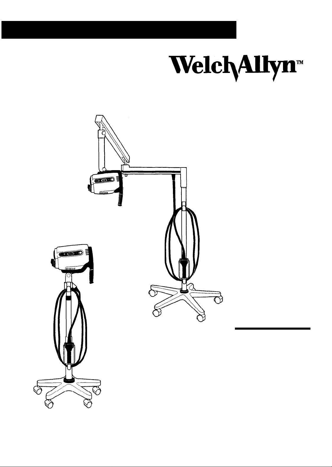
VideoPathTM Colposcope
Stand Alone Colposcope
Women's Health
Operating
Instruction
Manual
Page 2

Table of Contents
Conventions
General Precautions
Symbols
Summary of Warnings and Cautions
Components
VideoPathh
VideoPath Light Source
Optional Accessory
Nomenclature
VideoPath
VideoPath
VideoPath
Vertical Pole Stand
Swing Arm Stand
. . . . . . . . . . . . . . . . . . . . . . . . . . . . . . . . . . . . . . . . . .
.................................................................................
..................................................................................................
................................................................................................
Colposcope
.............................................................................................
Colposcope Front View
Colposcope Side View
Colposcope Back View
...........................................................................
..........................................................................
.................................................................................
..................................................................................
....................................................................................
. . . . . . . . . . . . . . . . . . . . . . . . . . . . . . . . . . . . . . . . . . . . . . . . . . . . . .
.......................................................
.........................................................
.........................................................
..........................................................
2
2
.3
3
4
.4
4
4
5
9
10
6
6
7
Monitor
Light Source
Connection Diagrams
Connecting
Connecting
Connecting
Preparation
General Precautions
Assembly
Vertical Pole Stand Assembly
...................................................................................................
............................................................................................
..............................................................................
VideoPath VLX-10/20
VideoPath
VCR/Video
Printer
VideoPathh
Use..
for
VideoPathh
of
...............................................................................
...............................................................................
Light Source with Monitor..
VLX- 10/20 Light Source with
..........................................................................
Colposcope
Colposcope
...............................................................
with Light Source..
....................................................
......................
.......
.8
9
11
..11
.11
.12
.13
13
.13
.13
Page 3

Swing Arm Stand Assembly
. . . . . . . . . . . . . . . . . . . . . . . . . . . . . . . . . . . . . . . . . . . . . . . . . . . . . . . . . . . . . . . . .
14
SettingUp
Operation
PowerSwitch
Focus and Zoom Controls
Green Filter Controls
Illumination Beam Director
Vertical Height Adjustment Ring
Swing Arm Height Adjustment
Right or Left Positioning of Swing Arm Colposcope
Positioning
Remote Video Functions
Storage of the VideoPath Colposcope Connector Terminal . . . . . . . . . . . . . . . . . . .17
Maintenance
VideoPath
VideoPathh
. . . . . . .
,...
. . . . . . . . . . . . . . . . . . . . . . . . . . . . . . . . . . . . . . . . . . . . . . . . . . . . . . . . . . . . . . . . . . . . . . . . . . . . . .
. . . . . . . . . . . . . . . . . . . . . . . . . . . . . . . . . . . . . . . . . . . . . . . . . . . . . . . . . . . . . . . . . . . . . . . . . . . . . . . . .
VideoPath
. . . . . . . . . . . . . . . . . . . . . . . . . . . . . . . . . . . . . . . . . . . . . . . . . . . . . . . . . . . . . . . . . . . . . . . . . . . . . . . . . . . . . . . . . . .
Colposcope Cleaning
Colposcope
. . . . . . . . . . . . . . . . . ..*.................................................
. . . . . . . . . . . . . . . . . . . . . . . . . . . . . . . . . . . . . . . . . . . . . . . . . . . . . . . . . . . . . . . . . . . . . . . . . . . . .
Colposcope
. . . . . . . . . . . . . . . . . . . . . . . . . . . . . . . . . . . . . . . . . . . . . . . . . . . . . . . . . . . . . . . . . . . . . . .
. . . . . . . . . . . . . . . . . . . . . . . . . . . . . . . . . . . . . . . . . . . .. . . . . .
. . . . . . . . . . . . . . . . . . . . . . . . . . . . . . . . . . . . . . . . . . . . . . . . . . . . . . . . . . . . . . . . . .
. . . . . . . . . . . . . . . . . . . . . . . . . . . . . . . . . . . . . . . . . . . . . . . . . . . . . . . . . .
. . . . . . . . . . . . . . . . . . . . . . . . . . . . . . . . . . . . . . . . . . . . . . . . . . . . . . . . . . . . .
. . . . . . . . . . . . . . . . . . . . . . . . . . .
. . . . . . . . . . . . . . . . . . . . . . . . . . . . . . . . . . . . . . . . . . . . . . . . . . . . . . .
. . . . . . . . . . . . . . . . . . . . . . . . . . . . . . . . . . . . . . . . . . . . .
. . . . . . . . . . . . . .
15
16
16
16
16
16
16
16
16
16
17
.18
18
Disinfecting Solutions
Illumination Lens Cleaning
Camera Lens Cleaning
Service Information
Troubleshooting
Specifications
. . . . . . . . . . . . . . . . . . . . . . . . . . . . . . . . . . . . . . . . . . . . . . . . . . . . . . . . . . . . . . . . . . . . . . . . . . . . . . . . . . . . . . . . . . . .
. . . . . . . . . . . . . . . . . . . . . . . . . . . . . . . . . . . . . . . . . . . . . . . . . . . . . . . . . . . . . . . . . . . . . . . . . . . . . . . . .
. . . . . . . . . . . . . . . . . . . . . . . . . . . . . . . . . . . . . . . . . . . . . . . . . . . . . . . . . . . . . . . . . . . . . . . . . . . . . . . . . . . . . . . .
. . . . . . . . . . . . . . . . . . . . . . . . . . . . . . . . . . . . . . . . . . . . . . . . . . . . . . . . . . . . . . . . . . . . . . . . . . .
. . . . . . . . . . . . . . . . . . . . . . . . . . . . . . . . . . . . . . . . . . . . . . . . . . . . . .
. . . . . . . . . . . . . . . . . . . . . . . . . . . . . . . . . . . . . . . . . . . . . . . . . . . . . . . . . . . . . . . . . . . . . . . . . .
. . . . . . . . . . . . .
18
18
18
19
20
21
Page 4

Thank you for purchasing the Welch Allyn
1
found in this manual and your VideoPath Colposcope will provide you with many years of reliable service. Please read these
instructions thoroughly before attempting to use your new VideoPath Colposcope.
CAUTION: Federal law restricts sale of this device to, or on the order of, a physician or other
appropriately licensed medical professional.
VideoPath
Colposcope. Follow the operation and maintenance instructions
IMPORTANT:
equipment.
INDICATIONS FOR USE: For examination of the tissues of the vagina, cervix, and external genitalia, to investigate, by
means of magnification, abnormal cervical cytology or suspicious lesions of the lower female genital tract. Also used for
corresponding biopsy and treatment, when indicated.
NOTE: This device complies with the guidelines of the American Conference of Governmental Industrial Hygienists’
threshold limits values for ultraviolet radiation for exposure time and distance consistent with the intended use of this device.
The material outlined in this manual should be reviewed and understood prior to operation of the
Page 5

Conventions
CAUTION:
or moderate injury and/or damage to the equipment. They also alert against unsafe practices.
NOTE: Notes provide supplemental information to the text and indicate a potentially hazardous situation, which, if not
avoided, may result in property damage. They also highlight important information on the use of this equipment.
Cautions indicate a potentially hazardous situation that, if not avoided, may result in minor
General Precautions
.
For safety, the VideoPath Colposcope should only be connected to either Welch Allyn VideoPath model number
VLX-10 or VLX-20 Light Sources.
.
The VideoPath Colposcope should not be operated in the presence of flammable or explosive gases or chemicals, or
installed in areas where these materials are commonly used.
.
Keep all liquids away from electrical equipment to avoid the possibility of shock and instrument damage.
.
Occasionally inspect the umbilical cord and plug for signs of cuts, abrasions or other damage.
.
The VideoPath Colposcope should never be stored or operated in areas where it could get wet or could be exposed to
any environmental conditions such as extreme temperature or humidity, direct sunlight, dust, etc.
.
The illumination light is extremely bright. DO NOT stare directly into illumination beam director when the Light
Source lamp is lit.
.
All service to the VideoPath Colposcope must be performed by Welch Allyn or by an authorized repair center.
.
VideoPath Colposcope user should adhere to the operating conditions found in this manual and the applicable Light
Source manual. Otherwise, instrument damage may occur and/or operator/patient safety may be compromised.
.
There are no user serviceable parts in this unit or in its accessories. Any attempt to disassemble and/or repair this unit
will result in voiding of the warranty.
.
Do not immerse any portion of the VideoPath Colposcope.
2
Page 6
Symbols
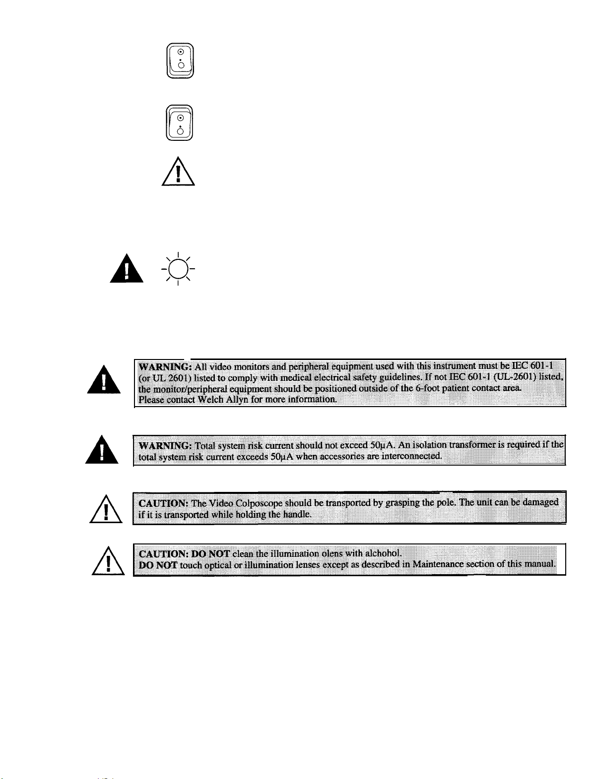
On: Power: Connects to the low voltage supply.
0
6
cl
!
A
Off: Power: Disconnects from the low voltage supply.
Caution: Consult user’s manual for additional information.
Warning: Consult user’s manual for additional information.
A
A
Summary of Warnings and Cautions
XJ-
Warning: High-intensity light
3
Page 7
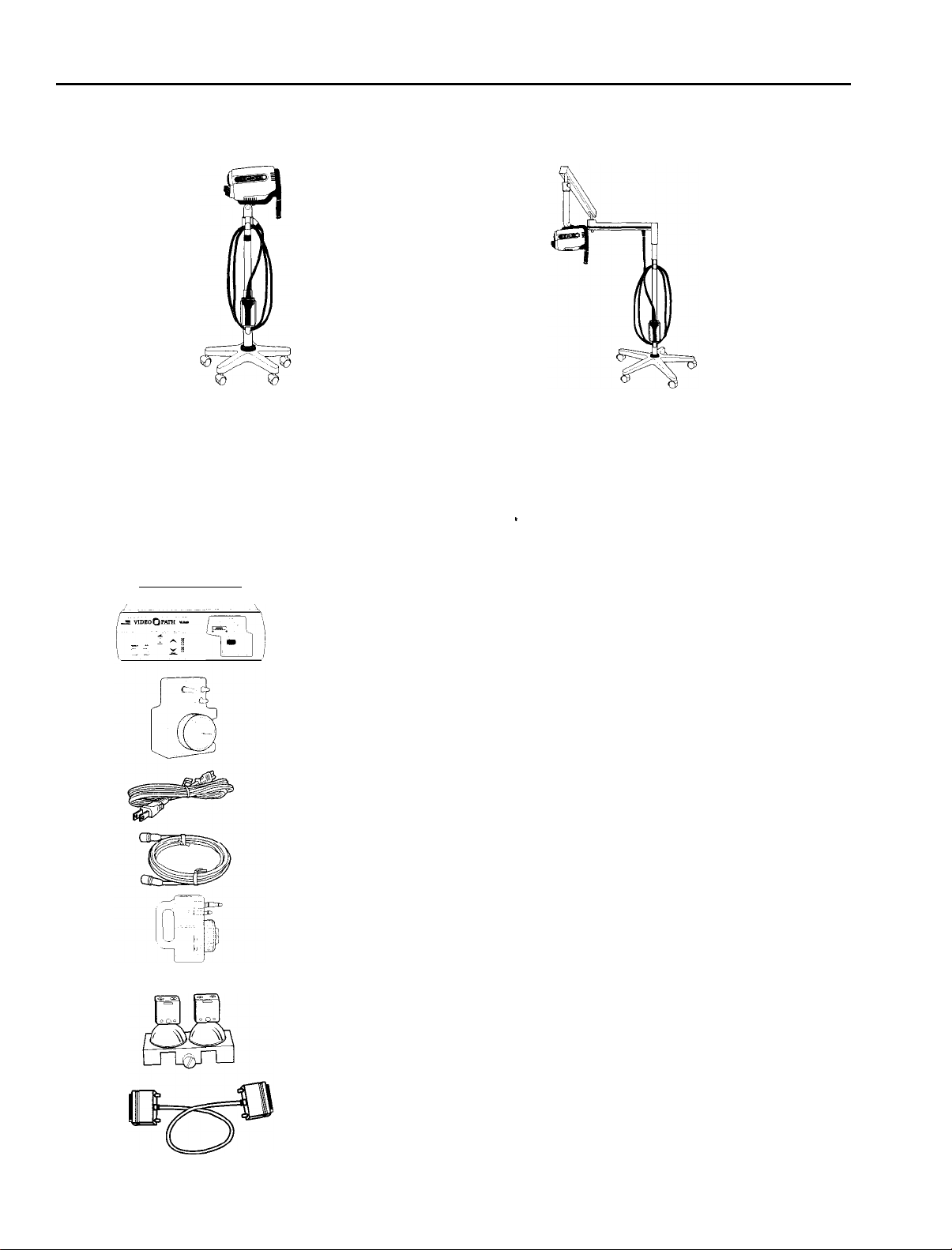
Components
VideoPath Colposcope
The video colposcope includes . .
.
VideoPath Colposcope and vertical stand models
88100/88110
Vertical stand hardware kit:
l Allen wrench
l Mounting cap
VLX-10/VLX-20
Light Source Includes:
VideoPath Colposcope and swing arm stand models
89100/89110
Swing arm hardware kit:
l Allen wrench
l Mounting washer
l Bolt
.
Optional Accessory
40500 Light Source (VLX- 10)
45500
45510
Light Source (VLX-20)
Water Bottle (Not applicable for VideoPath Colposcope)
761076-0 Power Cord
45512
45520
S-Video Cable
Cleaning/Disinfection Bottle (Not applicable for
VideoPath Colposcope)
04060
Lamp Replacement Assembly
65158
RS232 Interface Cable
NOTE: Only accessories and components indicated in this manual are to be used
with the Welch Allyn Video Colposcope system.
4
Page 8
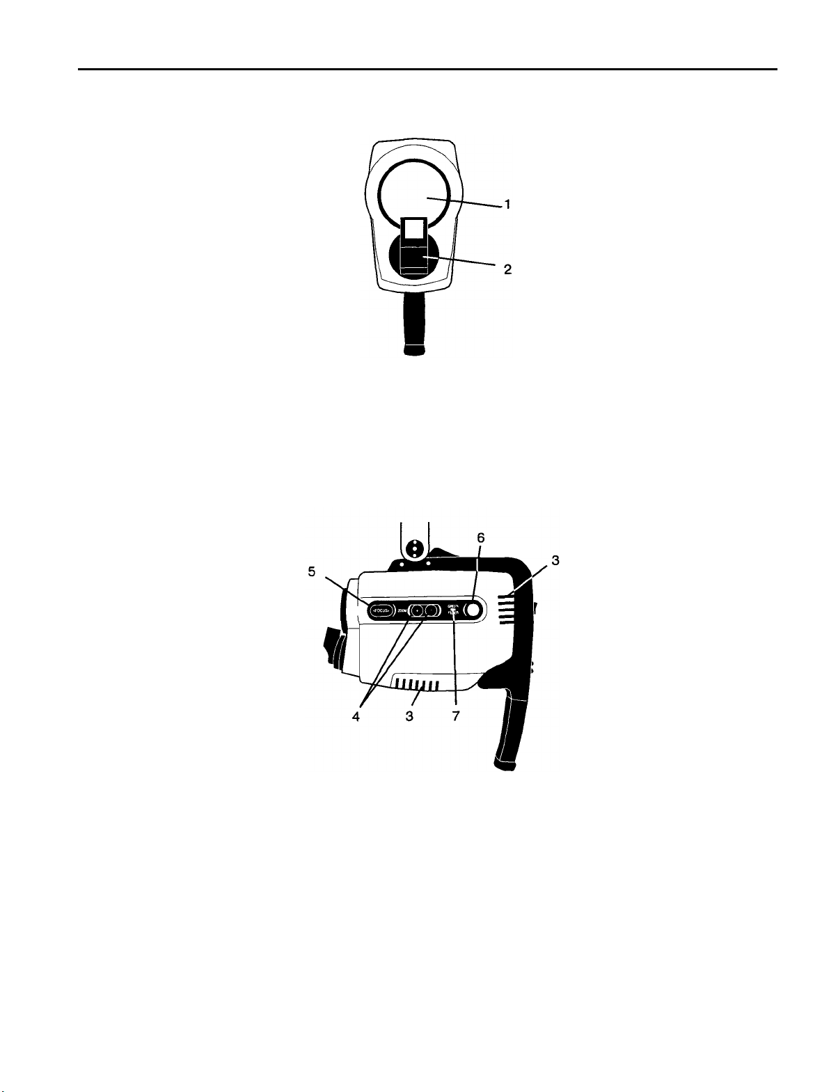
Nomenclature
5
VideoPath Colposcope Front View
Name
1. Objective lens
2. Illumination beam director
VideoPath Colposcope Side View
Function
The lens that establishes the magnification and field of view.
Directs light beam.
Name
3. Ventilation slots
4. Zoom control button
5. Focus control button
6. Green filter button
7. LED indicator
Function
Allow air to enter and leave unit, cooling internal components.
Pressing + or - increases or decreases magnification accordingly.
Pressing < or > adjusts the focus.
Pressing turns the electronic green filter on or off.
Illuminates if the electronic green filter is on. Flashes during activation
or deactivation.
Page 9

VideoPath Colposcope Back View
9-
11
10
Name
8. Power switch
9. Ventilation slots
10. VideoPath Colposcope handle
11. Remote video function buttons
Vertical Pole Stand
Function
Power control for the VideoPath Colposcope.
Allow air to enter and leave unit, cooling internal components.
For positioning the colposcope in the proper up/down, left/right
position.
Allow use of remote video printer functions.
(When equipped. Models 88110, 89110 only)
Name
12. Vertical rolling base stand
13. Colposcope connector terminal cord
14. Colposcope connector terminal
15. Colposcope connector terminal hook
16. Colposcope connector terminal hanger
17. Height adjustment ring
Allows vertical movement and locking of stand at desired height;
Function
Allows mobility with 5-caster base, including two locking casters.
Couples colposcope camera to colposcope terminal connector.
Couples colposcope to Welch Allyn Light Source Model VLX- 10
or VLX-20.
Storage hook to support umbilical cord.
Storage hanger to support colposcope connector terminal.
vertical height adjustment 36”-46” (91.4 cm to 116.8 cm).
6
Page 10

Swing Arm Stand
7
18
Name
18. Swing arm rolling base stand
19. Stop pin
20. Light Guide
21. Electrical Contacts
Function
Allows overhead positioning of the instrument with 5-caster weighted
base, including two locking casters; vertical height 29.5” to 49.5”
(74.9 cm to 125.7 cm).
Prevents positioning of colposcope in a configuration that limits lateral
adjustment.
Transmit light from the Light Source lamps to and through the
illumination beam director.
Electrical connection from the light source to the VideoPath Colposcope.
7
Page 11

Monitor
NOTE: The following is a brief overview of the nomenclature of the Sony PVM-1350 Video Monitor. For detailed
instructions, please refer to the operation manual that is provided by the manufacturer.
Front Panel of Monitor Back Panel of Monitor
30
29
282624
i
32
PLEASE REFERENCE YOUR SONY MONITOR MANUAL FOR FURTHER INFORMATION.
Name
22.
Power
23.
Volume
24.
Contrast
25.
Phase (tint)
Function
Press to turn the monitor on. The indicator will light up in green.
No
function.
Turn clockwise to increase contrast and counterclockwise to decrease it.
Turn clockwise to make the skin tones greenish and counterclockwise to
make them purplish.
26.
Chroma
Turn clockwise to make the color intensity higher and counterclockwise to
make it lower.
Bright (brightness)
27.
28.
Aperture (sharpness)
Menu button
29.
Degauss button
30.
Turn clockwise for more brightness and counterclockwise for less.
Turn clockwise for more sharpness and counterclockwise for less.
On-screen programmable controls of the picture.
Press this button momentarily. The screen will be demagnetized. Wait for
10 minutes or more before activating this button again.
Input select buttons
31.
Press (light on) to select the program to be monitored.
A: For signal fed through the LINE A connector.
B:
For signal fed through the LINE B connector.
C:
For signal fed through the LINE C connector.
(This is the Y/C (S-Video) input signal.)
RGB: For signal fed through the RGB connectors.
Power supply cord receptacle
32.
Couples with power cord, which should be plugged into a 110-120 VAC
hospital grade outlet (220-240 volt, 50 cycle for international).
Line A, line B connectors
33.
34.
Line C connector Y/C (S-Video)
Two groups (A and B) of line input connectors for composite video.
High resolution S-Video input.
NOTE: This monitor is shipped with default picture settings. Any change of the on-screen controls may result in
poor picture quality.
8
Page 12

Light Source (Front View)
9
37
Main power switch
35.
Air pump switch
36.
Lamp ignition
37.
Lamp standby indicator
38.
Colposcope connector port
39.
Air output port
40.
Picture brightness control
41.
35 36
38 41
Primary power control for the Light Source. If not activated, other controls
will not function.
Not applicable to
Activates the lamps when switch is depressed and main power switch
is on.
When
LED blinks, lamps cannot be ignited even if lamp ignition switch
is depressed.
Accepts VideoPath Colposcope umbilical plug to transmit light and
electrical signals to the colposcope.
Not applicable to
Not applicable to the VideoPath Colposcope.
VideoPath
VideoPath
Colposcope.
Colposcope.
9
Page 13

Light Source (Back View)
10
45
48
43
44
/
/
46
42.
Power supply cord receptacle
43.
S-Video
44. Composite
45. Earth ground terminal connector Provides a terminal that is connected to earth ground through the VLX-20
46. Equipotentiality terminal connector Accepts ground connector from electrosurgery equipment to provide a
47. RS-232 communication connector por
48. Auxilliary port
Couples with power cord, which should be plugged into a
grade outlet.
Outputs S-Video or Y/C, 4 pin DIN. (Dual connection, VLX 20 only)
Outputs NTSC (composite video), BNC connector. (Not applicable with
the VideoPath Colposcope)
line cord (1/4-36 UNS-2A thread). (VLX 20 only)
secondary or redundant ground path. (VLX 20 only)
t
Communication port for use with video printers.
No function. Future capability.
I
115V
hospital-
(VLX 20 only)
(VLX 20 only)
10
Page 14

Connection Diagrams
Connecting
The diagram below illustrates an example of recommended coupling between the
Connecting VideoPath VLX-1
The diagram below illustrates an example of recommended coupling between the
VideoPath VLX-10/20
0/20
Light Source with Monitor
S-Video Out
Light Source with VCR/Video Printer
VLX-10/20
VLX-10/20
and a monitor.
and peripheral equipment.
, S-Video In
I
I
Monitor
NOTE: The RS-232 cable is required for the Function Control Buttons to perform properly.
11
Page 15

Connection Diagrams
Connecting the VideoPath Colposcope with Light Source
12
Page 16

Preparation For Use
General Precautions
Make sure the unit is always grounded and secure during use. Do not disable power cord ground connection. Grounding
reliability is achieved only when power cord is connected to a hospital-grade receptacle. Inspect the electrical plug and cord
routinely. Do not use if damaged. Do not use the VideoPath Colposcope in the presence of any flammable anesthetics.
Do not open the VideoPath Colposcope housing. An electrical shock hazard exists due to high voltage. There are no user
serviceable parts inside the VideoPath Colposcope.
NOTE: Opening of the VideoPath Colposcope housing by an unauthorized repair facility will void the product warranty.
Assembly of VideoPath Colposcope
Before initial set up of the VideoPath Colposcope, check all components received against the parts list of components (see
Components section of this manual) to verify a complete set. If parts are missing, please notify Welch Allyn. Review the
Nomenclature, Preparation for Use, Operation and Maintenance sections to become familiar with the equipment.
Vertical Pole Stand Assembly
The VideoPath Colposcope stand is shipped unassembled. Minimal assembly is required.
1.
To assemble the stand, remove the stand and base parts from their cartons.
2.
Place base upside down on the floor and insert casters into holes on the bottom of the base. (Do not place two locking
casters next to each other.)
Locking caster
49
I
Locking caster
.lP-
=
‘*
3.
Place the base on the floor with casters down. Lock the two locking casters.
4.
Place pole in the base and screw the mounting cap onto the end using the enclosed Allen wrench. Be sure to tighten
securely. (The assembly may need to be tilted.)
5.
Before using the VideoPath Colposcope, refer to “Setting Up VideoPath Colposcope” section of this manual.
13
Page 17

Swing Arm Stand Assembly
The VideoPath Colposcope stand is shipped unassembled. Minimal assembly is required.
NOTE: Base weighs 58 lbs. Assistance may be required to lift.
To assemble the stand, remove the stand and base parts from the cartons.
1.
Place base upside down on the floor and insert casters into holes on the bottom of the base. (Do not place two locking
2.
casters next to each other.)
Locking caster
Place the base on the floor with casters down. Lock the two locking casters.
3.
4.
Place the vertical pole section of the assembly into the base.
5.
Locate the packaged mounting washer and bolt.
Place the bolt through the washer into the bottom of the pole. (The assembly may need to be tilted.)
6.
+/i/i
‘?W?!!!F
I
I
I
0
9
a
eiir
Locking caster
7.
Tighten securely with the enclosed Allen wrench.
8.
Remove the bolt from the arm of the colposcope assembly and insert it through the hole near the top of the pole.
Position the pole and the arm of the remaining
9.
colposcope assembly in close proximity.
Tighten the bolt securely with the enclosed Allen
10.
wrench.
Before using the VideoPath Colposcope, refer to
11.
“Setting Up
this manual.
VideoPath Colposcope” section of
/
14
Page 18

Setting Up VideoPath Colposcope
1.
Connect the Light Source power cord to the power cord receptacle on the back of the Light Source.
2.
Plug the remaining end of the power cord into a properly grounded 11
3.
Connect the S-Video cable to the S-Video output located on the back of the Light Source and connect the other end of
the S-Video cable into the line C connector Y/C (S-Video) on the back of the monitor.
4.
Plug the colposcope connector terminal into the connector port of
the Light Source. The umbilical plug should fully engage and
“click” into place.
5.
Activate the Power switch on the front panel. The green Lamp Ignition/Standby light will blink for
approximately 11 seconds.
Standby LED Light
_
-
0 -
120 volt AC outlet.
itor
’
Line C Y/C In
6.
Once the green Lamp Ignition/Standby
light remains lit, press the Lamp Ignition
Switch. The lamps will ignite and the
Lamp Ignition/Standby light will go out.
The lamps require 11 seconds to warm
up. This length of time will be indicated
by the center LED of the Picture
Brightness Indicator, which blinks until
the lamps reach full intensity. Once the
Picture Brightness Indicator remains constant, the lamps are fully warmed up, and the system is ready for use.
NOTE:
ignition Standby LED will remain blinking and lamp ignition cannot occur.
If the Light Source is powered up without having the VideoPath Colposcope attached, the lamp
$$he
Brightness
Indicator
Page 19

Operation
Power Switch
With the Light Source power cord connected to a properly grounded outlet, the S-Video cable connected to the Light Source
and monitor, and lamps activated, activate the power switch on the handle of the VideoPath Colposcope.
Focus and Zoom Controls
Once the power switch has been activated, the VideopPath Colposcope will execute a setup procedure, ending in the low
magnification setting, or
300 mm from the target. Adjust the VideoPath Colposcope by moving the stand (for vertical stand), or the arm (for the swing
arm stand), until the picture is in focus. Press the + on one of the zoom controls until maximum magnification is obtained,
and readjust the position of the stand or the swing arm until the picture is in focus. Fine focus, in either direction, is provided
by the focus controls once coarse focus has been achieved. After coarse focus is achieved at maximum magnification, zoom
control can be set to a desired lower magnification by pressing either zoom control. Focus will be maintained throughout the
entire magnification range once these steps have been completed, if the VideoPath Colposcope or target is not moved.
NOTE: The setup (nominal) setting of the focus controls can be recovered by pressing one of the zoom + controls for
4 seconds after maximum magnification has been achieved.
Green Filter Controls
Activate the electronic green filter by pressing the green button located on either side of the VideoPath Colposcope. Full
activation of the green filter occurs in less than 10 seconds. Deactivated the filter by pressing the green filter button again.
The green filter LED indicator flashes during activation and deactivation and remains on after activation is complete.
4.5x.
To obtain coarse focus, position the distal end of the VideoPath Colposcope approximately
Illumination Beam Director
The illumination beam director can be rotated up to 45” clockwise or counterclockwise to better illuminate the examination
area. To rotate the director, grasp the flat sides and twist in either direction as desired. The illumination beam director moves
with some resistance. This helps to hold it securely in the desired position. The center position can be recovered by returning
the director to the detent position.
Vertical Height Adjustment Ring (Vertical Colposcope Models
The height of the vertical stand can be adjusted by rotating the black height adjustment ring, located on the pole of the stand,
counterclockwise. Once the ring has been loosened, adjust the pole to the desired height and then tighten the ring again by
rotating it clockwise.
Swing Arm Height Adjustment (Swing Arm Colposcope Models 89100
Adjust the height of the swing arm stand by loosening the height adjustment knob located on the arm of the stand. The swing
arm can then be moved to the desired position. After moving the arm, tighten knob
desired drag can be obtained by adjusting this knob either clockwise or counterclockwise.
Right or Left Positioning of Swing Arm (Swing Arm Colposcope Models 89100
The swing arm of the VideoPath Colposcope can be positioned to the right or left side of the exam table. To alter the position
of the swing arm, pull down the stop pin located under the elbow of the swing arm while rotating the swing arm to the
desired side. Release the stop pin once the desired position is achieved.
88100 &
88110 Only)
&
89110 Only)
securely by rotating clockwise. The
&
89110 Only)
Positioning VideoPath Colposcope
The VideoPath Colposcope can be angled up and down and left and right. To change the up/down tilt angle, loosen the knob
located on the tilt axis. The
knob located on the support shaft. The drag of either knob can be set by loosening or tightening as necessary.
VideoPath Colposcope can then be tilted as necessary. To change the horizontal angle, loosen the
16
Page 20

Remote Video Functions (for VideoPath Colposcope Models 88110
The handle of the VideoPath Colposcope contains three buttons that control three video functions. These functions, provided
by a remote video printer, are Freeze, Print and Toggle. (See Connection Diagram section of this manual for connecting the
printer to the VideoPath Colposcope.) The VideoPath Colposcope models 88110 and 89110, when used with the VLX-20
Light Source and compatible video printer, have the ability to capture, store and print images. The function controls on the
VideoPath Colposcope interface with the system for convenient control of the Freeze, Copy and Video features. The
RS-232 cable must be connected from the VLX-20 Light Source.
Pressing the freeze ("F") button stores a new image in printer memory. The frozen image is displayed on the monitor.
&
89110 Only)
Pressing the copy
when the button was pressed will be printed.
Pressing the video
video to printer memory (frozen image), depending on the current mode.
Storage of the
When the VideoPath Colposcope is removed from the Light Source, the colposcope connector terminal should be stored in
the receptacle hanger.
1.
To properly place the VideoPath Colposcope connector plug in the hanger, remove the plug from the Light Source.
("C")
button prints the image displayed on the monitor. If live video is displayed, the image visible
("V")
button changes the display from printer memory (frozen image) to live video, or from live
VideoPath
Colposcope Connector Terminal
2.
Wrap the cord in a loop using the VideoPath Colposcope connector terminal hooks located on the colposcope stand.
3.
Place the VideoPath Colposcope connector terminal into the hanger as indicated.
L
Page 21

Maintenance
VideoPath
Colposcope Cleaning
IMPORTANT
Be careful not to allow solution to drip into the air vents.
DO NOT spray solution into the air vents.
DO NOT sterilize any part of the unit.
DO NOT IMMERSE any part of the unit in cleaning solutions.
Turn the power switch off and unplug the connector terminal cord from the Light Source prior to cleaning.
The VideoPath Colposcope housing and connector terminal cord can be wiped down with a cloth dampened slightly with a
mild solution of disinfectant. Be careful not to allow the plug prongs to get wet. Also be careful not to allow the camera lens
or lamp lens to get wet.
Disinfecting Solutions
The disinfecting solutions listed below are safe for cleaning the housing of the VideoPath Colposcope if used according to
the manufacturer’s instructions for cleaning and disinfecting, and in accordance with procedures detailed in the cleaning
section of this manual.
l Cidex, Cidex Plus
l 70% isopropyl alcohol
l 10% mild bleach solution
l
Metracide
l 10% Wescodyne
l
Banicide
l
Wavecide-01
NOTE: References to brand names are not endorsements of their efficacy as disinfecting solutions. However, tests have
shown these solutions to be compatible with Welch Allyn colposcopes, providing the manufacturers’s directions are
followed. Do not use any other solutions unless a sample has been sent to Welch Allyn for compatibility testing.
Illumination Lens Cleaning
The lamp lens may be cleaned with a cloth dampened slightly with warm water and mild detergent.
Camera Lens Cleaning
The camera lens may be cleaned with isopropyl alcohol or any commercial lens cleaner.
18
Page 22

Service Information
Customers in North America should return instruments requiring service to the Welch Allyn Technical Service Department
listed below, or to an authorized Welch Allyn distributor. The part and serial numbers are located on the VideoPath
colposcope connection terminal.
Technical Service Department
Welch Allyn, Inc.
4341 State Street Road
Skaneateles Falls, NY 13153-0220
U.S.A.
Telephone: 800-669-9771
Fax: 315-685-4653
19
Page 23

Troubleshooting
Condition
Power does not come on.
No image on monitor. Monitor/other peripheral devices
Dim image on monitor.
Lamp will not light.
(No illumination)
Printer does not respond
properly to handle
buttons.
(model #s 88110, 89110)
back into outlet. At the same time, turn printer off
Unplug power cord from wall outlet, then plug cord
Light source’s power cord
Light source
Colposcope power switch
Light source’s lamp housing door
Light source’s fuse blown Remove fuse panel and replace blown fuse with
Light source’s power socket
Cable connections
Colposcope
Lamps
Monitor input selection
Colposcope connector terminal
Light source
Power cord and pnnter
Printer
RS-232 cable not connected
between VLX-20 and video printer Connect RS-232.
Check
Action
Make sure proper connection at unit and wall outlet.
Make sure lightsource is on.
Make sure power switch on colposcope is on.
Make sure lamp housing door is properly closed.
T2.0A-250V.
Plug the power cord into a socket known to work.
Make sure power is on for all devices.
Make sure all video cables are connected properly.
(Use S-video cable only)
Make sure the colposcope is properly connected.
Advance colposcope connector terminal until it clicks
into place.
Make sure lamps are ignited.
Make sure correct input selection is made on the
monitor front panel.
Colposcope connector terminal not properly engaged.
Make sure lamp assembly is properly installed. Make
sure lamps are not burned out.
and
then on again.
Make sure printer is on and is properly connected.
Video printer not in proper signal
input mode
Printer not adjusted to proper
baud rate
Check light source to make sure
light source is properly connected
and on.
20
Adjust video printer until proper input mode is
selected. (S-video)
Set printer to 9600 baud. If changed, turn printer off
and then on.
Page 24

Specifications
Item
Power requirements
Dimensions
Weight
Focal length
Magnification
Field of view
Specification
Voltage
Frequency
Current
Vertical stand
Swing arm stand
Optical centerline to swing arm
bottom
Colposcope HxWxD (excluding
handles)
Vertical stand
Swing arm stand
300 mm
4.5x -
25x (typ.)
66
mm - 14 mm
Technical Data
115 VAC domestic
50/60
Hz
See Light
Low:
(91.4 cm to 116.8 cm)
Low:
(74.9 cm to 125.7 cm)
15.0” (38.1 cm)
8.25” x 5.75” x 3.37”
(21.0 cm x 14.6 cm x 8.6 cm)
29 lbs (13.2 kg)
84 lbs (38.1 kg)
Source manual.
36.0",
high: 46.0”
29.5",
high: 49.5”
Depth of field
Operating environment
Light Source Illumination
112mm - 5mm
Ambient temperature
Relative humidity
Atmospheric pressure
Lamp type
Lamp life
Brightness adjustment
Lamp
Lamp voltage
50o F to 104o F
95% max
70kPa to
Dual 21 Watt metal halide arc
750 hrs
Automatic electronic shutter (camera)
Welch Allyn part no. 04060
60 Volts
@
(+10o)
110kPa
1 hr per start
C to
+40o C)
21
Page 25

Specifications
Item
Cooling method
Color system
Video output
Transport/Storage environment
Output devices
Compliance
Listed
Specification
Forced air via fan (Light source)
Color mosaic CCD
Y/C (S-Video)
Ambient temperature
Relative Humidity
VCR
Monitor
Thermal or video printer
Complies
Explosion proofing
Technical Data
45o F (-40o C) to 122o F
95% max
UL2601-1
CAN/CSA
Use with potentially flammable
surroundings is prohibited.
C22.2 No. 601.1
(+50o C)
Fuses
Classification
Patents
See applicable light source
Electro medical equipment
Degree of Protection
against electrical shock
This product is covered by the
following patents:
5,117,154;
5,291,100.
Patents pending.
5,083,059;
5,138,228; 5,144,201;
Class I equipment
Type B (light source)
22
Page 26

Welch Allyn, Inc.
4341 State Street Road
P.O. Box 220
Skaneateles Falls, NY 13153-0220
Telephone: 315-685-4560
l-800-535-6663
Part No. 881014
Rev. A
 Loading...