

Page 1
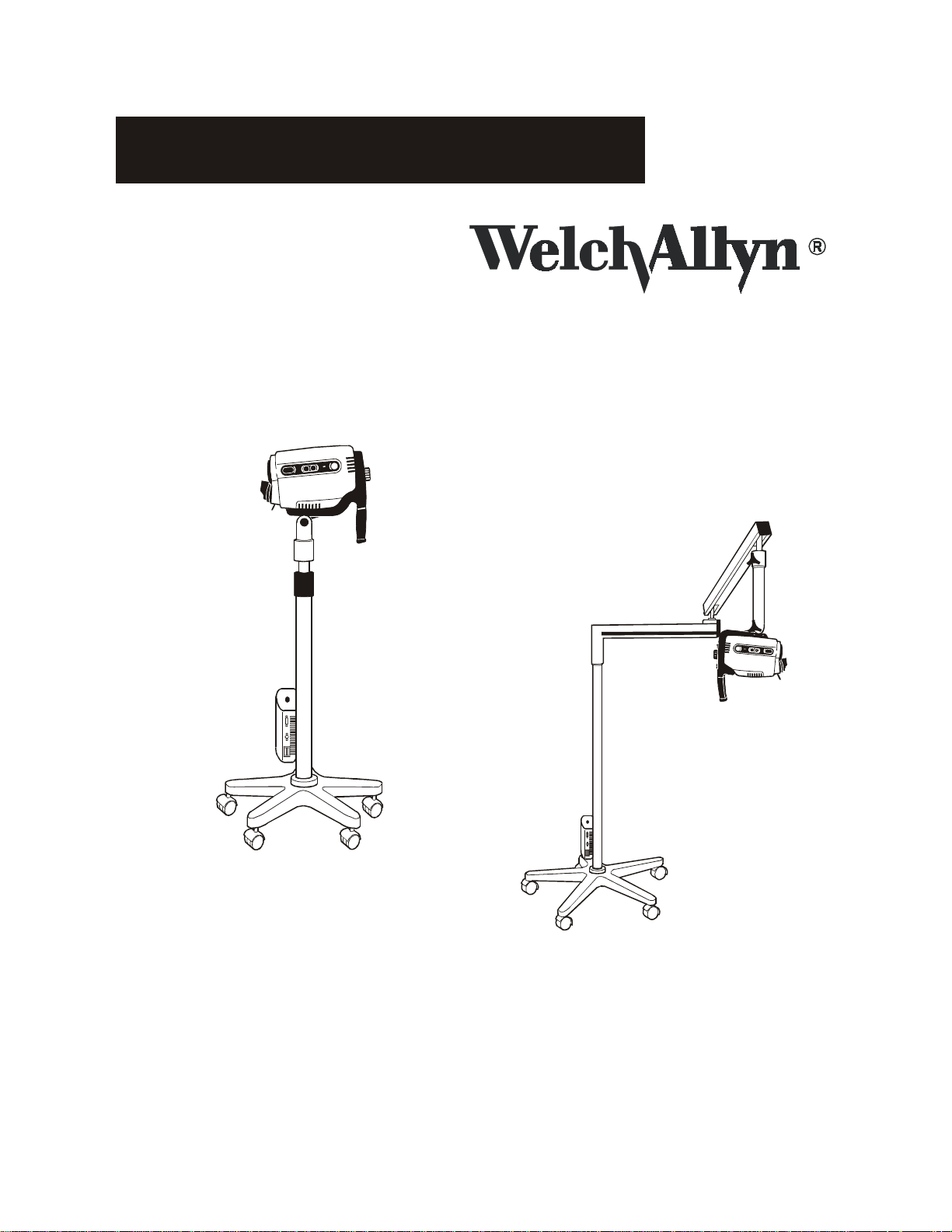
Welch Allyn Video Colposcope
Women's Health
Service Manual
Models 88000A/89000A
Operating Instruction Manual
Page 2

Page 3

Table of Contents
Conventions . . . . . . . . . . . . . . . . . . . . . . . . . . . . . . . . . . . . . . . . . . . . . . . . . . . . . . . . . . . . 2
General Precautions . . . . . . . . . . . . . . . . . . . . . . . . . . . . . . . . . . . . . . . . . . . . . . . . . . . . . . . . . . . . . . . 2
Symbols . . . . . . . . . . . . . . . . . . . . . . . . . . . . . . . . . . . . . . . . . . . . . . . . . . . . . . . . . . . . . . . . . . . . . . . . 3
Summary of Warnings and Cautions . . . . . . . . . . . . . . . . . . . . . . . . . . . . . . . . . . . . . . . . . . . . . . . . .4
Components . . . . . . . . . . . . . . . . . . . . . . . . . . . . . . . . . . . . . . . . . . . . . . . . . . . . . . . . . . . . 5
Video Colposcope . . . . . . . . . . . . . . . . . . . . . . . . . . . . . . . . . . . . . . . . . . . . . . . . . . . . . . . . . . . . . . . . 5
Optional Accessories . . . . . . . . . . . . . . . . . . . . . . . . . . . . . . . . . . . . . . . . . . . . . . . . . . . . . . . . . . . . . . 5
Nomenclature . . . . . . . . . . . . . . . . . . . . . . . . . . . . . . . . . . . . . . . . . . . . . . . . . . . . . . . . . . . 7
Video Colposcope Front View . . . . . . . . . . . . . . . . . . . . . . . . . . . . . . . . . . . . . . . . . . . . . . . . . . . . . . .7
Video Colposcope Side Views . . . . . . . . . . . . . . . . . . . . . . . . . . . . . . . . . . . . . . . . . . . . . . . . . . . . . . . 7
Video Colposcope Back View . . . . . . . . . . . . . . . . . . . . . . . . . . . . . . . . . . . . . . . . . . . . . . . . . . . . . . .8
Video Colposcope Bottom View . . . . . . . . . . . . . . . . . . . . . . . . . . . . . . . . . . . . . . . . . . . . . . . . . . . . .8
Vertical Pole Stand . . . . . . . . . . . . . . . . . . . . . . . . . . . . . . . . . . . . . . . . . . . . . . . . . . . . . . . . . . . . . . . 9
Swing Arm Stand . . . . . . . . . . . . . . . . . . . . . . . . . . . . . . . . . . . . . . . . . . . . . . . . . . . . . . . . . . . . . . . . . 9
Monitor . . . . . . . . . . . . . . . . . . . . . . . . . . . . . . . . . . . . . . . . . . . . . . . . . . . . . . . . . . . . . . . . . . . . . . . .10
Front Panel of Monitor . . . . . . . . . . . . . . . . . . . . . . . . . . . . . . . . . . . . . . . . . . . . . . . . . . . . . . . . . . .10
Back Panel of Monitor . . . . . . . . . . . . . . . . . . . . . . . . . . . . . . . . . . . . . . . . . . . . . . . . . . . . . . . . . . . .10
Connection Diagrams . . . . . . . . . . . . . . . . . . . . . . . . . . . . . . . . . . . . . . . . . . . . . . . . . . . . 11
Connecting Video Colposcope with Monitor . . . . . . . . . . . . . . . . . . . . . . . . . . . . . . . . . . . . . . . . . .11
Connecting Video Colposcope with VCR/Video Printer . . . . . . . . . . . . . . . . . . . . . . . . . . . . . . . . .12
Preparation for Use . . . . . . . . . . . . . . . . . . . . . . . . . . . . . . . . . . . . . . . . . . . . . . . . . . . . . 13
General Precautions . . . . . . . . . . . . . . . . . . . . . . . . . . . . . . . . . . . . . . . . . . . . . . . . . . . . . . . . . . . . . .13
Assembly of Video Colposcope . . . . . . . . . . . . . . . . . . . . . . . . . . . . . . . . . . . . . . . . . . . . . . . . . . . . .13
Vertical Pole Stand Assembly . . . . . . . . . . . . . . . . . . . . . . . . . . . . . . . . . . . . . . . . . . . . . . . . . . . . . .13
Swing Arm Stand Assembly . . . . . . . . . . . . . . . . . . . . . . . . . . . . . . . . . . . . . . . . . . . . . . . . . . . . . . . 14
Setting Up Video Colposcope . . . . . . . . . . . . . . . . . . . . . . . . . . . . . . . . . . . . . . . . . . . . . . . . . . . . . .15
Page 4

Operation . . . . . . . . . . . . . . . . . . . . . . . . . . . . . . . . . . . . . . . . . . . . . . . . . . . . . . . . . . . . . 16
Power Switch . . . . . . . . . . . . . . . . . . . . . . . . . . . . . . . . . . . . . . . . . . . . . . . . . . . . . . . . . . . . . . . . . . . 16
Lamp Ignition . . . . . . . . . . . . . . . . . . . . . . . . . . . . . . . . . . . . . . . . . . . . . . . . . . . . . . . . . . . . . . . . . . 16
Focus and Zoom Controls . . . . . . . . . . . . . . . . . . . . . . . . . . . . . . . . . . . . . . . . . . . . . . . . . . . . . . . . . 16
Mag Index Control . . . . . . . . . . . . . . . . . . . . . . . . . . . . . . . . . . . . . . . . . . . . . . . . . . . . . . . . . . . . . . . 16
Green Filter Control . . . . . . . . . . . . . . . . . . . . . . . . . . . . . . . . . . . . . . . . . . . . . . . . . . . . . . . . . . . . . 16
Polarization Filter Control . . . . . . . . . . . . . . . . . . . . . . . . . . . . . . . . . . . . . . . . . . . . . . . . . . . . . . . . 16
Illumination Beam Director . . . . . . . . . . . . . . . . . . . . . . . . . . . . . . . . . . . . . . . . . . . . . . . . . . . . . . . 16
Vertical Height Adjustment Ring (Vertical Colposcope Model Only) . . . . . . . . . . . . . . . . . . . . . . 16
Swing Arm Height Adjustment (Swing Arm Colposcope Model Only) . . . . . . . . . . . . . . . . . . . . 16
Positioning Video Colposcope . . . . . . . . . . . . . . . . . . . . . . . . . . . . . . . . . . . . . . . . . . . . . . . . . . . . . 17
Remote Video Functions . . . . . . . . . . . . . . . . . . . . . . . . . . . . . . . . . . . . . . . . . . . . . . . . . . . . . . . . . . 17
Maintenance . . . . . . . . . . . . . . . . . . . . . . . . . . . . . . . . . . . . . . . . . . . . . . . . . . . . . . . . . . . 17
Video Colposcope Cleaning . . . . . . . . . . . . . . . . . . . . . . . . . . . . . . . . . . . . . . . . . . . . . . . . . . . . . . . 17
Disinfecting Solutions . . . . . . . . . . . . . . . . . . . . . . . . . . . . . . . . . . . . . . . . . . . . . . . . . . . . . . . . . . . . 17
Illumination Lens Cleaning . . . . . . . . . . . . . . . . . . . . . . . . . . . . . . . . . . . . . . . . . . . . . . . . . . . . . . . 17
Camera Lens Cleaning . . . . . . . . . . . . . . . . . . . . . . . . . . . . . . . . . . . . . . . . . . . . . . . . . . . . . . . . . . . . 18
Replacing Lamp . . . . . . . . . . . . . . . . . . . . . . . . . . . . . . . . . . . . . . . . . . . . . . . . . . . . . . . . . . . . . . . . . 18
Replacing Fuses . . . . . . . . . . . . . . . . . . . . . . . . . . . . . . . . . . . . . . . . . . . . . . . . . . . . . . . . . . . . . . . . . 20
Service Information . . . . . . . . . . . . . . . . . . . . . . . . . . . . . . . . . . . . . . . . . . . . . . . . . . . . . 21
Troubleshooting . . . . . . . . . . . . . . . . . . . . . . . . . . . . . . . . . . . . . . . . . . . . . . . . . . . . . . . . 22
Specifications . . . . . . . . . . . . . . . . . . . . . . . . . . . . . . . . . . . . . . . . . . . . . . . . . . . . . . . . . . 23
Page 5
Thank you for purchasing the Welch Allyn Video Colposcope. Follow the operation and maintenance instructions found in
this manual and your video colposcope will provide you with many years of reliable service. Please read these instructions
thoroughly before attempting to use your new video colposcope.
CAUTION: Federal law restricts sale of this device to, or to the order of, a physician or other appropriately
licensed medical professional.
WARNING: Users of this equipment should be thoroughly trained in the appropriate medical procedures. Furthermore, they should take the time to read and understand these instructions before performing any procedure. They should also read and understand the instructions for any other equipment used in conjunction with
the video colposcope (i.e. electrosurgical generators). Failure to do so may result in injury to the patient and/or
damage to the video colposcope.
IMPORTANT: The material outlined in this manual should be reviewed and understood prior to operation of the equipment.
NOTE: This equipment has been tested and complies with emissions standard EN60601-1-2: 1993, CISPR Publication
11:1990/EN55011: 1991 for Radiated and Conducted Emissions, Group 1, Class B.
This equipment also has been tested and complies with susceptibility standards to electrostatic discharge (ESD), radiated electromagnetic fields, fast transient bursts, and conducted surge interference. The procedures and criteria for conformance are
contained in IEC801-2, 801-3, 801-4, 801-5, and EN60601-1-2: 1993.
In addition, this equipment has been tested and complies with EN6000-3-2 (1st Edition) covering harmonic disturbances in
supply systems caused by household appliances and similar electrical equipment, Part 2, and EN 6000-3-3 (1st Edition) covering voltage fluctuation disturbances in supply systems caused by household appliances and similar electrical equipment Part
3.
INDICATIONS FOR USE: For examination of the tissues of the vagina, cervix, and external genitalia, to investigate, by means
of magnification, abnormal cervical cytology or suspicious lesions of the lower female genital tract. Also used for corresponding biopsy and treatment, when indicated.
NOTE: This device complies with the guidelines of the American Conference of Governmental Industrial Hygienists
threshold limits values for ultraviolet radiation for exposure time and distance consistent with the intended use of
this device.
1
Page 6

Conventions
WARNING: Warnings alert the user to the possibility of serious injury, death, or other adverse reaction associated with the
use or misuse of the device.
CAUTION: Cautions indicate a potentially hazardous situation that, if not avoided, may result in minor or moderate injury
and/or damage to the equipment. They also alert against unsafe practices.
NOTE: Notes provide supplemental information to the text and indicate a potentially hazardous situation, which, if not
avoided, may result in property damage. They also highlight important information on the use of this equipment.
General Precautions
• For safety, the video colposcope should only be coupled to a grounded 110-120 VAC hospital-grade outlet (220 - 240 volt,
50 cycle international).
• The video colposcope should not be operated in the presence of flammable or explosive gases or chemicals, or installed in
areas where these materials are commonly used.
• To avoid overheating, the video colposcope should not be positioned closer than 6” to any wall.
• Keep all liquids away from electrical equipment to avoid the possibility of shock and instrument damage.
• Occasionally inspect the power cord for signs of cuts, abrasions or dents.
• The video colposcope should never be stored or operated in areas where it could get wet or could be exposed to any environmental conditions like extreme temperature or humidity, direct sunlight, dust, etc.
• The lamp is extremely bright. DO NOT stare directly into illumination lens when the lamp is lit.
• All service to the video colposcope must be performed by Welch Allyn or by an authorized repair center.
• Video colposcope user should adhere to the operating conditions found in this manual. Otherwise, instrument damage
may occur and/or operator/patient safety may be compromised.
• There are no user servicable parts (other than the lamp and fuses) in this unit or in its accessories. Any attempt to disassemble and/or repair this unit will result in voiding of the warranty.
2
Page 7
Symbols
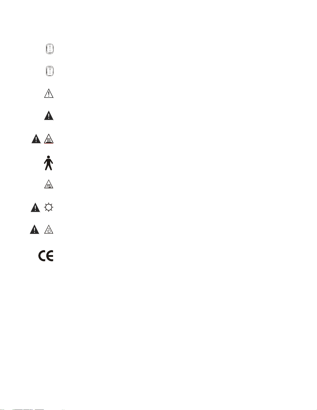
On: Power: Connects to the low voltage supply.
Off: Power: Disconnects from the low voltage supply.
Caution: Consult user's manual for additional information.
War n ing: Consult user's manual for additional information.
War n ing: High temperatures
Type B Equipment
Risk of fire. Replace fuses as marked.
War n ing: High-intensity light
War n ing: Power supply of unit is energized whenever power cord is plugged in.
The CE mark on this product indicates it has been tested to and conforms with the provisions noted in the 93/
42/EEC Medical Device Directive.
Authorized European Representative:
European Regulatory Manager
Welch Allyn, Ltd.
Kells Road, Navan,
County Meath, Republic of Ireland
Tel 353 46 79060
Fax 353 46 27128
3
Page 8
Summary of Warnings and Cautions
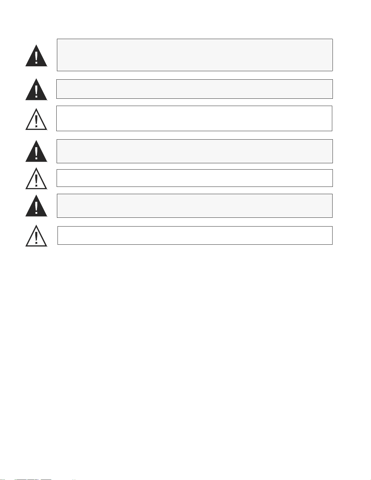
WARNING: All video monitors and peripheral equipment used with this instrument must be IEC 601-1 (or
UL 2601) listed to comply with medical electrical safety guidelines. If not IEC 601-1(UL-2601) listed, the
monitor/peripheral equipment should be positioned outside of the 6-foot patient contact area.Please contact
Welch Allyn for more information.
WARNING: Total system risk current should not exceed 50µA. An isolation transformer is required if the
total system risk current exceeds 50µA when accessories are interconnected.
CAUTION: The video colposcope is cooled via a vent fan located in the back of the unit. The fan draws air in
from beneath the video colposcope and exhausts the air out the back of the video colposcope. Verify that the
unit is no less than 6" from a wall.
WARNING: DO NOT use a converter adapter that will convert the three-prong AC plug to a two-prong line
plug. The power supply in the video colposcope will not be properly grounded and electric shock might
result.
CAUTION: DO NOT clean illumination lens with alcohol. DO NOT touch optical or illumination lenses
except as described in Maintenance section of this manual.
WARNING: The lamp operates at a high temperature. DO NOT attempt to remove the lamp before allowing
it to cool. Allow at least five minutes for the lamp to cool before replacing. Replace with Welch Allyn lamp
#09800 only.
CAUTION: The colposcope can be damaged if the unit is transported while holding the handle. The unit
should be transported by grasping the pole.
4
Page 9
Components
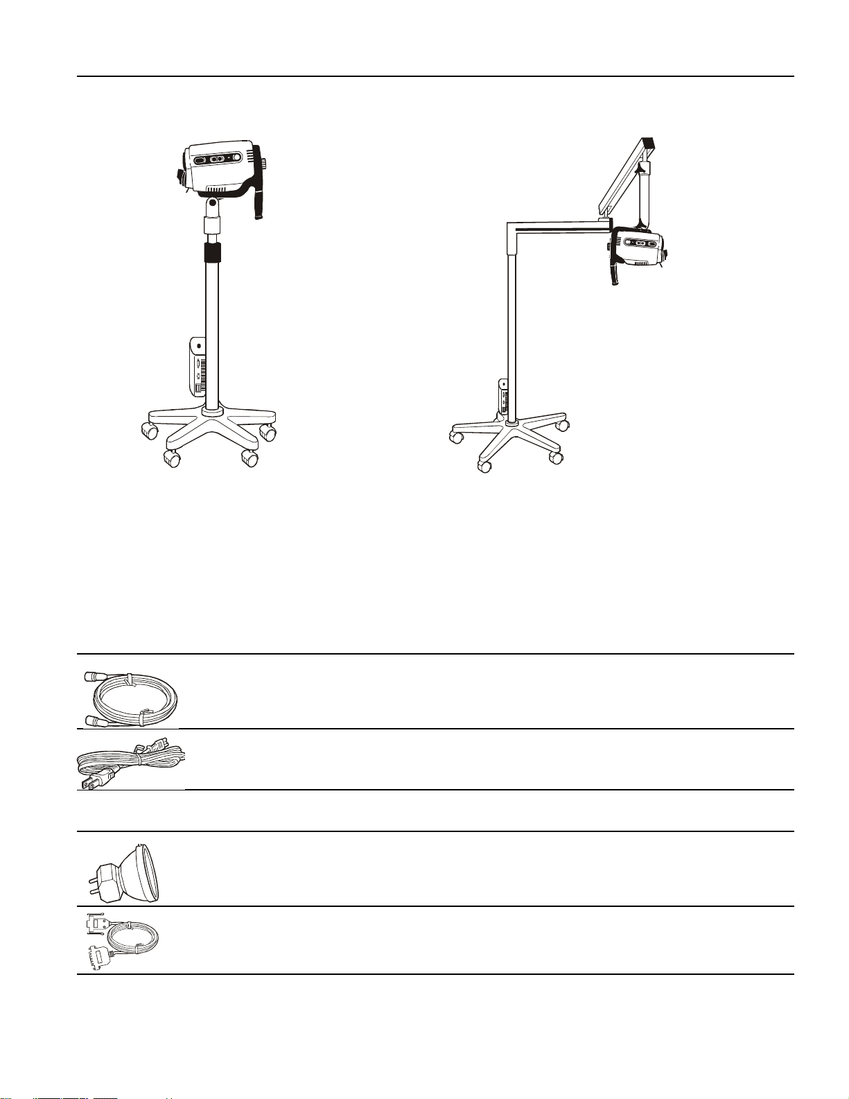
Video Colposcope
88000A
Video colposcope and vertical stand with
vertical stand hardware kit:
• Allen wrench
• Allen bolt
• Mounting washer
• Spacer
88600 S-Video Cable
761076-0 Power Cord
Optional Accessories
09800 Replacement Lamp
89000A
Video colposcope and swing arm stand
with swing arm hardware kit:
• Allen wrench
• Bolt
88500 RS-232 Interface Cable
5
Page 10

488307-9 Replacement Fuse (2 required)
88010 Cervical Model
88040 Dust Cover for Vertical Stand
89040 Dust Cover for Swing Arm
88030 Vertical Stand with Base Only
89030 Swing Arm Stand with Base Only
NOTE: Only accessories and components indicated in this manual are to be used with the Welch Allyn Video Colposcope
system.
6
Page 11

Nomenclature
Video Colposcope Front View
1
2
Name Function
1. Objective Lens The lens that establishes the magnification and field of view.
2. Illumination beam director Directs lamp beam.
Video Colposcope Side Views
6
5
3
8
4
3
7
Name Function
3. Ventilation slots Allow air to enter and leave unit, cooling internal components.
4. Zoom control button Pressing + or - increases or decreases magnification accordingly.
5. Fine Focus control button Pressing < or > adjusts the focus.
6. Green filter button Pressing turns the electronic green filter on or off.
7. Green filter LED indicator Illuminates if the electronic green filter is on.
8. Polarization filter control Adjusts the proportion of glare removed from the image.
9. Mag button Displays magnification index on screen.
10. Mag LED indicator Illuminates if Mag Index is on.
9
10
5
4
7
Page 12

Video Colposcope Back View
11
12
14
15
13
Name Function
11. Power switch Power control for the video colposcope.
12. Ventilation slots Allow air to enter and leave unit, cooling internal components.
13. Video colposcope handle For positioning the colposcope in the proper up/down, left/right position.
14. Attachment knob Fastens handle to video colposcope.
15. Remote video function buttons Allow use of remote video printer functions.
Video Colposcope Bottom View
17
18
Name Function
16. Lamp access door Removes for lamp replacement. (Note: If door is not properly closed, interlock power
switches will not activate and the lamp will not start.)
17. Ventilation slots Allow air to enter and leave unit, cooling internal components.
18. Mounting piece Allows the video colposcope to attach to the stand. On the swing arm model, the
mounting piece is located at the top of the colposcope. On the vertical stand model, the
mounting piece is located at the bottom of the colposcope.
16
8
Page 13

Vertical Pole Stand
24
23
22
20
19
Name Function
19. Vertical rolling base stand Allows mobility with 5-caster base, including two locking casters.
20. Fuse drawer Opens for replacement of fuses.
21. Power supply cord receptacle Couples with power cord, which should be plugged into a 110-120 VAC hospital-grade
outlet (220-240 volt, 50 cycle international).
22. S-Video output Outputs Y/C (S-Video).
23. RS232 interface cable output Couples with RS232 interface cable.
24. Height adjustment ring Allows vertical movement and locking of stand at desired height;vertical height adjust-
ment 36”-46” (91.4cm to 116.8cm).
21
Swing Arm Stand
27
25
Name Function
25. Swing arm rolling base stand Allows overhead positioning of the instrument with 5-caster weighted base, including
two locking casters; vertical height 29.5” to 49.5” (74.9cm to 125.7cm).
26. Power supply cord receptacle Couples with power cord, which should be plugged into a 110-120 VAC hospital-grade
outlet (220-240 volt, 50 cycle international).
27. Fuse drawer Opens for replacement of fuses.
26
9
Page 14

Monitor
NOTE: The following is a brief overview of the nomenclature of the Sony PVM-14N1U Video Monitor. For detailed
instructions, please refer to the operation manual that has been provided by the manufacturer
Front Panel of Monitor
28
29
30
PLEASE REFERENCE YOUR SONY MONITOR MANUAL FOR FURTHER INFORMATION.
31
32
33
Back Panel of Monitor
36
35
34
Name Function
28. Power Switch Press to turn the monitor on. The indicator lights in green. To turn the monitor power
off, press again.
29. Line A/Line B Press Line A if the signal is fed through a Line A connector on the back of (input select)
the monitor. Press Line B if the signal is fed through a Line B connector on the back of
the monitor.
30. Menu/Exit Press to make the on-screen menu appear. Press again to leave the on- screen menu. The
following parameters can be modified using the on- screen menu system:
Volume - No function.
Contrast - Adjust the contrast of the screen using the arrow buttons.
Brightness - Adjust the brightness of the screen using the arrow buttons.
Chroma - Adjust the color intensity of the video signal using the arrow buttons.
Phase - Adjust the phase of the video signals using the arrow buttons.
Color Select - Select the color system of the current input signals.
Language - Select the menu language.
User memory - Select options for storing and recalling menu settings.
31. Down Arrow In item selection menus, moves the cursor downward. In adjustment and setting
menus, decreases the value of the selected item or moves downward through item
selections.
32. Up Arrow In item selection menus, moves the cursor upward. In adjustment and setting menus,
increases the value of the selected item or moves upward through item selections.
33. Enter Chooses the selected item. Is active only during the first level of on-screen selections.
34. Power supply Couples with power cord, which should be plugged into a 110-120 VAC hospital grade
cord receptacle outlet (220-240 volt, 50 cycles for international).
35. Line A/Line B Video In Input connectors for composite video.
36. Line A/Line B Y/C In Input connectors for high resolution S-Video
NOTE: This monitor is shipped with default picture settings. Any change of the on-screen controls may result in poor
picture quality.
10
Page 15

Connection Diagrams
Connecting Video Colposcope with Monitor
S-Video Cable
Line A Y/C In
Back Panel of Monitor
Connecting Video Colposcope with VCR/Video Printer
RS232 Interface Cable
S-Video In
S-Video Out
S-Video Cable
Line A Y/C In
Back Panel of Monitor
WARNING: All video monitors and peripheral equipment used with this instrument must be IEC 601-1 (or UL
2601) listed to comply with medical electrical safety guidelines. If not IEC 601-1(UL-2601) listed, the monitor/
peripheral equipment should be positioned outside of the 6-foot patient contact area. Please contact Welch Allyn
for more information.
11
Page 16

Preparation for Use
General Precautions
Make sure the unit is always grounded and secure during use. Do not disable power cord ground connection. Grounding reliability is achieved only when power cord is connected to a hospital-grade receptacle. Inspect the electrical plug and cord routinely. Do not use if damaged. Do not use the video colposcope in the presence of any flammable anesthetics.
Do not open the video colposcope housing. An electrical shock hazard exists due to high voltage. There are no user serviceable parts inside the video colposcope, except the lamp.
NOTE: Opening of the video colposcope housing by an unauthorized repair facility will void the product warranty.
WA R N I N G : Total system risk current should not exceed 50µA. An isolation transformer is required if the
total system risk current exceeds 50µA when accessories are interconnected.
CAUTION: The video colposcope is cooled via a vent fan located in the back of the unit. The fan draws air
in from beneath the video colposcope and exhausts the air out the back of the video colposcope. Verify that
the unit is no less than 6" from a wall.
WARNING: DO NOT use a converter adapter that will convert the three-prong AC plug to a two-prong line
plug. The power supply in the video colposcope will not be properly grounded and electric shock might
result.
.
CAUTION: The colposcope can be damaged if the unit is transported while holding the handle. The unit
should be transported by grasping the pole.
Assembly of Video Colposcope
Before initial set up of the video colposcope, check all components received against the parts list of components (see Components section of this manual) to verify a complete set. If parts are missing, please notify Welch Allyn. Review the Nomenclature, Preparation for Use, Operation, and Maintenance sections to become familiar with the equipment.
Vertical Pole Stand Assembly
The video colposcope stand is shipped unassembled. Minimal assembly is required.
1. To assemble the stand, remove the stand and base parts from their cartons.
Locking caster
2. Place base upside down on the floor and insert casters into
holes on the bottom of the base. (Do not place two locking
casters next to each other.)
3. Place the base on the floor with casters down. Lock the two locking casters.
12
Page 17

4. Place pole into the base, aligning the pin on the flange with the pin hole in the base. Place bolt, spacer, and washer, oriented as shown, into the pole. Tighten securely with the enclosed Allen wrench. (The assembly may need to be tilted.)
Was h er
Spacer
Hex Bolt
Allen Wrench
Align pin with hole
5. Before using the video colposcope, refer to “Setting Up Video Colposcope” section of this manual.
Swing Arm Stand Assembly
The video colposcope stand is shipped unassembled. Minimal assembly is required.
NOTE: BASE WEIGHS 58 LBS. YOU MAY REQUIRE ASSISTANCE TO LIFT IT.
1. To assemble the stand, remove the stand and base parts from the
cartons.
2. Place base upside down on the floor and insert casters into holes on
the bottom of the base. (Do not place two locking casters next to
each other.)
3. Place the base on the floor with casters down. Lock the two locking
casters.
4. Place the vertical pole section of
the assembly into the base, aligning
the pin on the flange with the pin
hole in the base.
5. Locate the packaged bolt.
6. Place the bolt through the bottom of
the pole. (The assembly may need
to be tilted.)
7. Tighten securely with the enclosed
Allen wrench.
8. Remove the bolt from the arm of the colposcope assembly and insert it through the hole near the top of the pole.
9. Position the pole and the arm of the remaining colposcope assembly in close proximity.
Hex Bolt
Allen Wrench
10. Connect the two wire harnesses via their connectors. (This may
require assistance for proper assembly.)
Locking caster
Align pin with hole
13
Page 18

11. Bring the colposcope swing arm assembly to the
pole while at the same time pushing the electrical
connectors into the colposcope arm.
12. Tighten the bolt securely with the enclosed Allen wrench. Be sure
not to pinch any of the electrical wires between the vertical pole and
arm of the colposcope assembly.
13. Before using the video colposcope, refer to Setting Up Video Colposcope section of this manual.
Setting Up Video Colposcope
1. Connect the power cord to the power cord receptacle in the power supply located on the video colposcope stand.
2. Plug the other end of the power cord into a properly grounded 110-120 volt AC outlet (220-240 volt, 50 cycle for international).
3. Connect the S-Video cable to the S-Video output on the side of the power supply located on the video colposcope stand.
4. Connect the other end of the S-Video cable into the Line C connector Y/C (S-Video) on the back of the monitor.
5. Plug the monitor into a properly grounded
110-120 volt AC outlet (220-240 volt, 50 cycle
for international).
RS232 output
S-Video output
14
Page 19

Operation
Power Switch
With the power cord connected to a properly grounded outlet, and the S-video cable connected to the video colposcope and
monitor, activate the power switch on the handle of the video colposcope.
Lamp Ignition
Once the video colposcope's power switch has been activated, the lamp will ignite. The lamp requires approximately 11 seconds to warm up.
Focus and Zoom Controls
Once the power switch has been activated, the video colposcope will execute a setup procedure, ending in the low magnification setting, or 4.5x. To obtain coarse focus, position the distal end of the video colposcope approximately 300mm (12”) from
the target. Adjust the video colposcope by moving the stand (for vertical stand), or the arm (for the swing arm stand), until the
picture is in focus. Press the + on one of the zoom controls until maximum magnification is obtained, and readjust the position
of the stand or the swing arm until the picture is in focus. Fine focus, in either direction, is provided by the focus controls
once coarse focus has been achieved. After coarse focus is achieved at maximum magnification, zoom control can be set to a
desired lower magnification by pressing either zoom control. Focus will be maintained throughout the entire magnification
range once these steps have been completed if the video colposcope or target is not moved.
NOTE: The setup (nominal) setting of the focus controls can be recovered by pressing one of the zoom + controls for 4
seconds after maximum magnification has been achieved.
Mag Index Control
Activate the magnification index button by pressing the blue button located on the right side of the colposcope (see Video Colposcope Side Views). The Mag Index refers to magnification relative to a 14” monitor. Deactivate the magnification index by
pressing the mag index control again.
To determine the magnification*, multiply the mag index by the number in the table below.
NUMBER BY WHICH
DISPLAY DEVICE
TO MULTIPLY MAG
INDEX
Sony 14” Monitor, model
PVM-14M2U
Sony video printer, model
UP2100 & model UP2300
Sony 20” Monitor, model
PVM-20N5U
*Magnification is the size of an object displayed on a display device (monitor, video print, etc.) divided by the actual size of the
object.
1.0 5 5
0.37 5 1.85
1.44 5 7.2
EXAMPLE:
Mag. Index on screen
EXAMPLE:
Magnification
Green Filter Control
Activate the electronic green filter by pressing the green button located on the left side of the video colposcope (see Video Colposcope Side Views). Deactivate the filter by pressing the green filter button again.
Polarization Filter Control
The Polarization Filter control can be rotated to reduce glare from the image as desired. The filter is completely engaged (minimum glare) when the control is fully rotated to the left. The filter can be disengaged by returning the Polarization Filter control
to the full right hand position.
15
Page 20

Illumination Beam Director
The illumination beam director can be rotated up to 45° clockwise or counterclockwise to better illuminate the examination
area. To rotate the director, grasp the flat sides and twist in either direction as desired. The illumination beam director moves
with some resistance. This helps to hold it securely in the desired position. The center position can be recovered by returning
the director to the detent position.
Vertical Height Adjustment Ring (Vertical Colposcope Model Only)
The height of the vertical stand can be adjusted by rotating the black height adjustment ring, located on the pole of the stand,
counterclockwise. Once the ring has been loosened, adjust the pole to the desired height and then tighten the ring again by
rotating it clockwise.
Swing Arm Height Adjustment (Swing Arm Colposcope Model Only)
Adjust the height of the swing arm stand by loosening the height adjustment knob located on the arm of the stand. The swing
arm can then be moved to the desired position. After moving the arm, tighten knob securely by rotating clockwise. The desired
drag can be obtained by adjusting this knob either clockwise or counterclockwise.
Positioning Video Colposcope
The video colposcope can be angled up and down and left and right. To change the up/down tilt angle, loosen the knob located
on the tilt axis. The video colposcope can then be tilted as necessary. To change the horizontal angle, loosen the knob located
on the support shaft. The drag of either knob can be set by loosening or tightening as necessary.
Remote Video Functions
The handle of the video colposcope contains three buttons that control three video functions. These functions, provided by a
remote video printer, are Freeze, Print, and Toggle. (See “Connection Diagrams” on page 11. of this manual for connecting the
printer to the video colposcope.)
1. Pressing the freeze (“F”) button stores a new image in printer memory. The frozen image is displayed on the monitor.
2. Pressing the copy (“C”) button prints the image displayed on the monitor. If live video is displayed, the image visible
when the button was pressed will be printed.
3. Pressing the video (“V”) button changes the display from printer memory (frozen image) to live video, or from live video to
printer memory (frozen image), depending on the current mode.
16
Page 21

Maintenance
Video Colposcope Cleaning
Turn the power switch off and unplug the power cord from the electrical outlet prior to cleaning.
The video colposcope housing can be wiped down with a cloth dampened slightly with a mild solution of disinfectant. Be
careful not to allow the plug prongs to get wet. Also be careful not to allow the camera lens or lamp lens to get wet.
Disinfecting Solutions
The disinfecting solutions listed below are safe for cleaning the housing of the video colposcope if used according to the manufacturer’s instructions for cleaning and disinfecting, and in accordance with procedures detailed in the cleaning section of
this manual.
• 70% isopropyl alcohol
• 10% mild bleach solution
• 10% Wescodyne
NOTE: References to brand names are not endorsements of their efficacy as disinfecting solutions. However, tests have
shown these solutions to be compatible with Welch Allyn colposcopes, providing the manufacturers' directions
are followed. Do not use any other solutions unless a sample has been sent to Welch Allyn for compatibility testing.
IMPORTANT
Be careful not to allow solution to drip into the air vents.
DO NOT spray solution into the air vents.
DO NOT sterilize any part of the unit.
DO NOT IMMERSE any part of the unit in cleaning solutions.
Illumination Lens Cleaning
The lamp lens may be cleaned with a cloth dampened slightly with warm water and mild detergent.
CAUTION: DO NOT clean illumination lens with alcohol. DO NOT touch optical or illumination lenses
except as described in Maintenance section of this manual.
Camera Lens Cleaning
The camera lens may be cleaned with isopropyl alcohol or any commercial lens cleaner.
17
Page 22

Replacing Lamp
WARNING: The lamp operates at a high temperature. DO NOT attempt to remove the lamp before allowing it
to cool. Allow at least five minutes for the lamp to cool before replacing. Replace with Welch Allyn lamp
#09800 only.
1. Turn the power switch off and unplug the power cord from the electrical outlet.
2. Holding the video colposcope
as shown, turn the knob
located at the back of the handle counterclockwise and
unscrew and remove the video
colposcope from the handle.
3. Place the unit on a suitable work surface.
Slide the lamp access
door away from the
housing as shown until
the door is completely
removed.
4. Unplug the lamp from the electrical connector.
18
Page 23

5. Push the retainer spring toward the back of the
colposcope and remove the lamp from its housing.
6. Remove a Welch Allyn replacement lamp # 09800 from its package. Do not touch the lamp itself or the interior reflective
surface of the lamp. Skin oils will cause premature lamp failure. Hold lamp by the outside of the reflector or the connector
only. Remove any grease or fingerprints with a clean cotton swab moistened with alcohol. Do not leave any lint on the
lamp.
7. Holding the retainer spring as in ’step 5’ , slide the new lamp into the lamp housing so that the lamp's alignment pin
engages the alignment slot in the lamp holder. (Make sure lamp is properly seated and snaps into place.)
8. Plug the electrical connector onto the new lamp.
9. Slide the lamp access door securely back into place, reversing the process described in ’step 3’ above.
10. Place the video colposcope back into the handle, making sure the power connector is engaged.
11. Tighten the knob by rotating clockwise until snug.
12. Plug the power cord back into the electrical outlet.
19
Page 24

Replacing Fuses
Two fuses are located in slots adjacent to the power supply cord receptacle on the side of the power supply housing. This
housing is attached to the pole of the video colposcope stand.
1. To replace a blown fuse, remove the fuse holder by
pressing the tab and pulling the holder out of the power
supply.
Ta b
2. Pull out and remove the
blown fuse from the fuse
holder.
3. Replace with new fuses # T1.00L-250V 1A Time lag/Low Breaking Capacity (Welch Allyn Part # 488307-9).
4. Reinsert the fuse holder by pressing until it snaps into place.
20
Page 25

Service Information
Customers in North America should return instruments requiring service to the Welch Allyn Technical Service Department
listed below, or to an authorized Welch Allyn distributor.
Technical Service Department
Welch Allyn, Inc.
4341 State Street Road
Skaneateles Falls, NY 13153-0220
U.S.A.
Telephone: 1-800-535-6663
Fax: 315-685-4653
Customers outside of North America should return their units to a local, authorized Welch Allyn distributor, or to their nearest
Welch Allyn service center.
Welch Allyn, Inc., U.S.A. - 4341 State Street Road, Skaneateles Falls, NY 13153-0220,
Tel: 800-535-6663, Fax: 315-685-4653
Welch Allyn, Ltd., Canada - 160 Matheson Blvd. E., Unit #3, Mississauga, Canada L4Z 1V4,
Tel: 905-890-0004, Fax: 905-890-0008
Welch Allyn, Ltd., UK - Aston Abbots, Buckinghamshire, England HP22 4ND,
Tel: 011-44-1296-682140, Fax: 011-44-1296-68210
Welch Allyn, GmbH, Germany - Zollerstrasse 2-4, D72417 Jungingen, Germany,
Tel: 011-49-7477-9271-73, Fax: 011-49-7477-9271-93
Welch Allyn, Ltd., Singapore - 6001 Beach Road #21-09, Golden Mile Tower, Singapore 199589,
Tel: 011-65-291-0882, Fax: 011-65-291-5780
Welch Allyn, Ltd., Australia - PO Box 132, Rydalmere, NSW 1701, Unit 5-38 South Street, Rydalmere NSW 2116,
Australia,
Tel: 011-61-294-183-155, Fax: 011-61-294-183-650
The part and serial numbers are located on the housing of the colposcope near the fan. Remove the colposcope from the handle
to locate these numbers.
21
Page 26

Troubleshooting
Condition Check Action
Power does not come on. Power Cord
Attachment of unit to handle
No image on monitor. Attachment of unit to handle
and door to unit
Fuses
Wall outlet
Monitor/other peripheral
devices
Cable connections
Monitor input selection
Lamp will not light. Lamp housing
Lamp
Lamp access door
Check connections at power supply and wall outlet.
Check colposcope unit’s alignment with handle.
Make sure lamp access door and handle are properly attached.
Remove fuse panel & replace blown fuse with
T1.00L 250V 1A time lag (Welch Allyn part number
# 488307-9).
Plug the power cord into a wall outlet known to
work.
Make sure power is on for all devices.
Make sure all video cables are connected properly.
Make sure correct input selection is made on the
front panel.
Make sure lamp assembly is installed properly.
Replace lamp.
Make sure lamp access door is properly closed.
Printer does not respond
properly to handle buttons.
Power cord and printer
Printer
Unplug power cord from wall outlet, then plug cord
back in to outlet. At the same time, turn printer off
and then on again.
Make sure printer is on and is properly connected.
22
Page 27

Specifications
Item Specification Technical Data
Power requirements Voltage
Frequency
Current
Dimensions Vertical Stand
Swing arm stand
Optical centerline to swing arm
bottom
Colposcope HxWxD (excluding
handles)
Weight Colposcope
Vertical Stand
Swing arm stand
Focal length 300 mm (12”)
Magnification (relative to a 14”
monitor)
4.5x - 30x (typ.)
115VAC domestic
220-240VAC international
50/60Hz
1.0 Amp
Low: 36.0”, high: 46.0”
(91.4 cm to 116.8 cm)
Low: 29.5”, high: 49.5”
(74.9 cm to 125.7 cm)
15.0” (38.1 cm)
8.25” x 5.75” x 3.37”
(21.0 cm x 14.6 cm x 8.6 cm)
3.1 lbs (1.4 kg)
25 lbs (11.3 kg)
80 lbs (36.3 kg)
Field of view 66mm - 14mm
Depth of field 112mm - 5mm
Operating environment Ambient temperature
Relative humidity
Atmospheric pressure
Illumination Lamp type
Lamp life
Brightness adjustment
Lamp
Lamp voltage
Cooling method Forced air via fan
Color system Color mosaic CCD
Video output Y/C (S-Video)
50° F (+10° C) to 104°F (+40° C)
95%
70kPa to 110kPa
21 Watt metal halide arc
750 hrs @ 1 hr per start
Automatic electronic shutter
Welch Allyn part no. 09800
60 volts
23
Page 28

Item Specification Technical Data
Transport/Storage environment Ambient temperature
Relative humidity
Output devices VCR
Monitor
Thermal or video printer
Compliance Listed
Listed
Listed
Certified
Conformace
Explosion proofing
Fuses T1.00L-250V
(Welch Allyn part # 488307-9)
Classification Electro medical equipment
Degree of protection against
electrical shock
-40°F (-40°C) to 120° F (+50° C)
95% max.
UL2601-1
CAN/CSA C22.2 No. 601.1
IEC 601-1
IEC601-1-2
CE*
Use with potentially flammable
surroundings is prohibited
1 Amp time lag,
low breaking capacity
Class I equipment
Typ e B
Patents This product is covered by the following patents:
5,083,059; 5,117,154; 5,138,228; 5,144,201; 5,291,100; D391,360,
D395,084; 5,840,012; 5,879,286; D416,088; 6,068,593; 6,147,705.
Patents pending
The CE mark on this product indicates it has been tested to and conforms with the provisions noted in the 93/42/
EEC Medical Device Directive.
Authorized European Representative:
European Regulatory Manager
Welch Allyn, Ltd.
Kells Road, Navan,
County Meath, Republic of Ireland
Tel 353 46 79060
Fax 353 46 27128
24
Page 29

Page 30

4341 State Street Road
Skaneateles Falls, NY 13153, U.S.A.
Tel.: 1-315-685-4560
Fax: 1-315-685-3361
Printed in the USA 880324 Rev. A
 Loading...