

Page 1
VideoPath
®
VG-2 00
VideoGastroscope
Operating
Manual
Endo Menu
Service Manual
Page 2
Thank you for your purchase of a Welch Allyn Flexible
VideoGastroscope. The operating and maintenance instructions
found in this manual should be followed to ensure many years of
reliable service. Please read these instructions thoroughly before
attempting to use your new Flexible VideoGastroscope.
WARNING: The user of this equipment should be thoroughly trained in
the medical procedures appropriate to the equipment. Furthermore, time
should be taken to read and understand these instructions before performing any procedures. Instructions for other equipment used in conjunction with any VideoEndoscope (e.g., suction machines) should also be
read and understood. Failure to do so may result in injury to the patient
and/or damage to the instrument.
While this manual describes the recommended protocol for inspecting
and operating the equipment, it does not outline procedural techniques.
Only physicians trained and versed in flexible endoscopy should use this
equipment.
CAUTION: Federal (USA) law restricts this device to sale by/to or on the
order of a physician or other appropriately licensed medical professional.
Infection Control Note
This manual includes a current list of disinfecting and sterilizing solutions
and processes. However, since infection control procedures involve
complex and controversial issues and are constantly changing, it is recommended that the users of this equipment keep informed of the latest
information and regulations pertaining to infection control.
The CE mark on this device indicates it has been tested to and conforms
with the provisions noted within the 93/42/EEC Medical Devices Directive.
Authorized European Representative Address:
European Regulatory Manager
Welch Allyn, Ltd.
Kells Road, Navan,
County Meath,
Republic of Ireland
Tel.: 353-46-79060
Fax: 353-46-27128
Page 3
Table of Contents
Conventions
WARNING: alerts the user to possible serious injury, death or other
adverse reaction associated with the use or misuse of the device.
CAUTION: indicates a potentially hazardous situation which, if not
avoided, may result in minor or moderate injury. It also alerts against
unsafe practices.
NOTE
: provides supplemental information to the text and indicates a
potentially hazardous situation, which, if not avoided, may result in
property damage. Additionally, it highlights important information on
the use of this equipment.
The Welch Allyn 31750 Gastroscope is intended to be used in facilitating
gastroscopy procedures.
VG-200 Gastroscope 1
Conventions ....................................................1
Specifications..................................................2
Symbols ..........................................................2
Warnings..........................................................2
Components....................................................3
Nomenclature and Function ..........................6
Flexible VideoGastroscope ..............................6
Light Source ......................................................8
Water Bottle/Cleaning Bottle ............................9
Preparation and Inspection for Use............10
Prior to Initial Use ..........................................10
System Set-up ................................................10
Physical System Inspection............................12
Operations ....................................................15
Procedure ......................................................15
Holding the Instrument....................................16
Preparation Before Insertion of the
VideoEndoscope ............................................16
Insertion and Withdrawal ................................17
Biopsy Passage..............................................18
Electrosurgery ................................................19
Video Printer ..................................................20
Cleaning and Disinfection............................20
Endoscope Internal Schematic ......................20
Semi-Automated Cleaning Method ............23
Cleaning at the Examination Room................23
Leakage Testing..............................................25
Disinfection Procedure (Total Immersion) ......27
Final Rinse......................................................28
Manual Cleaning Method ............................29
Cleaning at the Examination Room................29
Leakage Testing..............................................31
Cleaning the Instrument..................................33
Enzymatic Cleaning Solutions ........................35
Cleaning of Accessories – Biopsy Forceps....35
High-Level Disinfection ..................................36
Disinfecting Solutions......................................36
Sterilization and Aeration ............................37
Ethylene Oxide Gas Sterilization....................37
Cold Sterilization ............................................38
Other Sterilization Methods ............................38
Accessory Sterilization ....................................39
Accessory and Instrument Storage............39
Servicing........................................................40
Care and Maintenance Tips ........................41
Troubleshooting............................................43
Page 4
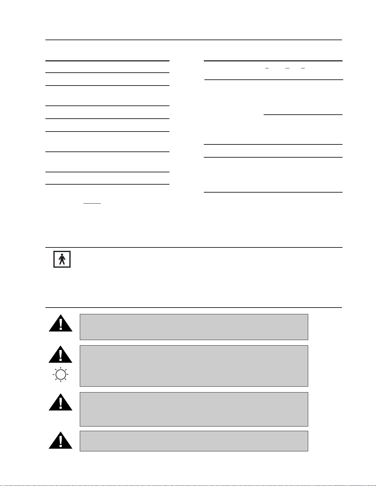
Symbols
Type BF IPX7 Protected against the effects of immersion
Warnings
WARNING: Total system risk current should not exceed 50µA. An isolation
transformer is required if the total system risk current exceeds 50µA when
accessories are interconnected.
WARNING: If the endoscope is removed from the light source, the lamps will
remain lit. DO NOT look directly into the lights. The intensity of the illumination
may damage your eyes. If the instrument is removed from the light source,
either turn off the main power switch or press the Lamp Ignition/Standby switch
to turn off the lamps and put them in a standby mode.
WARNING: High energy radiated light may be transmitted from the light
emission window of the endoscope, giving rise to high temperatures in front
of the light emission window. To minimize hazards, avoid prolonged exposure
or contact.
WARNING: DO NOT use this equipment in the presence of any flammable
anesthetics.
Specifications
2 VideoPath
Gastroscope
Parameter (31750)
Angle of View 120°
Depth of View 5-100mm
Tip Deflection Up: 210° Down: 120°
Right: 120° Left: 120°
Distal Rigid Diameter ∅10.0mm
Insertion Tube Diameter ∅9.8mm
Diameter of Accessory/ ∅2.8mm
Suction Channel
Insertion Tube 1050mm
Working Length
Total Length 1370mm
Gastroscope
Parameter (31750)
Function Controls- Freeze, Copy, Video
Communication Version Lockable Steering Brakes
Environment
Operating +10°C (50°F) to +40°C (104°F)
30 - 75% R.H.
700 hPa - 1060 hPa Altitude
Transport/Storage -20°C to +49°C
95% R.H. Max.
700 hPa - 1060 hPa Altitude
Operating Mode Continuous
Compliance UL 2601-1, IEC 60601-1,
IEC 60601-2-18,
CAN/CSA C22.2 No. 601.1,
EN 60601-1-2, CE
NOTE: This device complies with current required standards for electromag-
netic interference and should not present problems to other equipment
or be affected by other devices. As a precaution, avoid using this device
in close proximity to other equipment.
Page 5
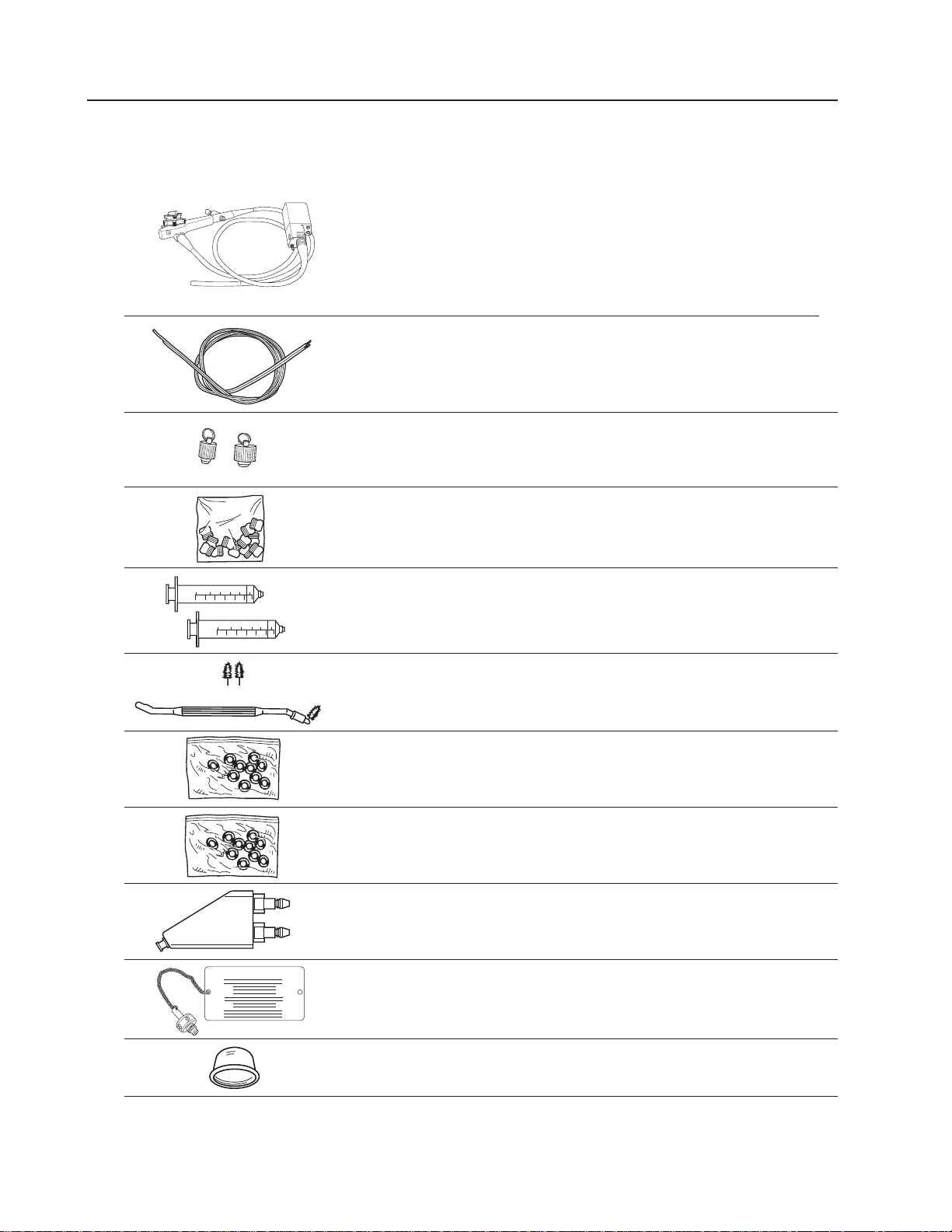
Components
Flexible VideoGastroscope Set Includes:
31750 Flexible VideoGastroscope
31020 Channel Cleaning Brush (2 each)
31021 Valve Reprocessing Caps
31039 (Biopsy Seals) Procedure Scope
31023 60cc Syringes (2 each)
33924 Air/Water Nozzle Cleaning Brush
31024 Air/Water Valve “O” Ring Kit
31025 Suction Valve “O” Ring Kit
31027 Air/Water Reprocessing Adapter
31029 Shipping/ETO Vent Cap
31730 Distal Reprocessing Cap (6 each)
VG-200 Gastroscope 3
ETO Vent Cap
Page 6
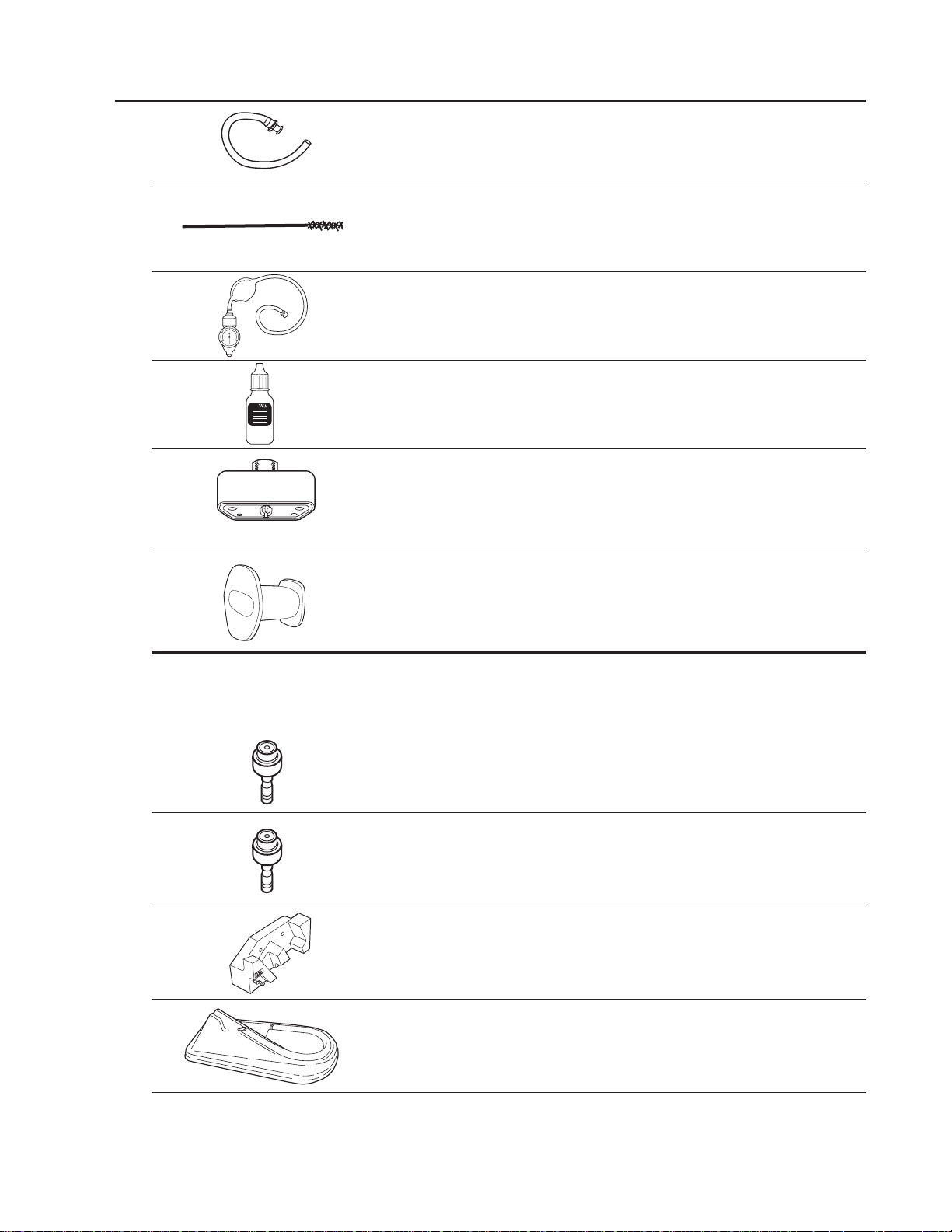
Components (continued)
31038 Suction Reprocessing Adapter
31031 Valve Well Cleaning Brush
31037 Leakage Tester
33918 Valve Lubricant
31028 Soaking Cap
31710 Disposable Bite Block (20 each)
Optional Accessories (not included in set):
31032 Air/Water Valve
31033 Suction Valve
31035 Instrument Hanger
33902 Disinfection Tray
4 VideoPath
Page 7
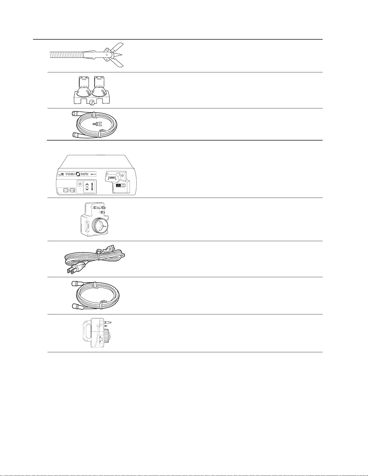
Components (continued)
33950 Biopsy Forceps with Needle
04060 Lamp Replacement Assembly
33915 Electrosurgical Ground Kit
VLX-20 Light Source Includes:
45500 Light Source
45510 Water Bottle
761076-0 Power Cord
45512 S-Video Cable
45520 Cleaning Bottle
VG-200 Gastroscope 5
POWER AIR
!
STANDBY
LAMP
IGNITION
LAMP
SERVICE
PICTURE
BRIGHTNESS
2
Page 8
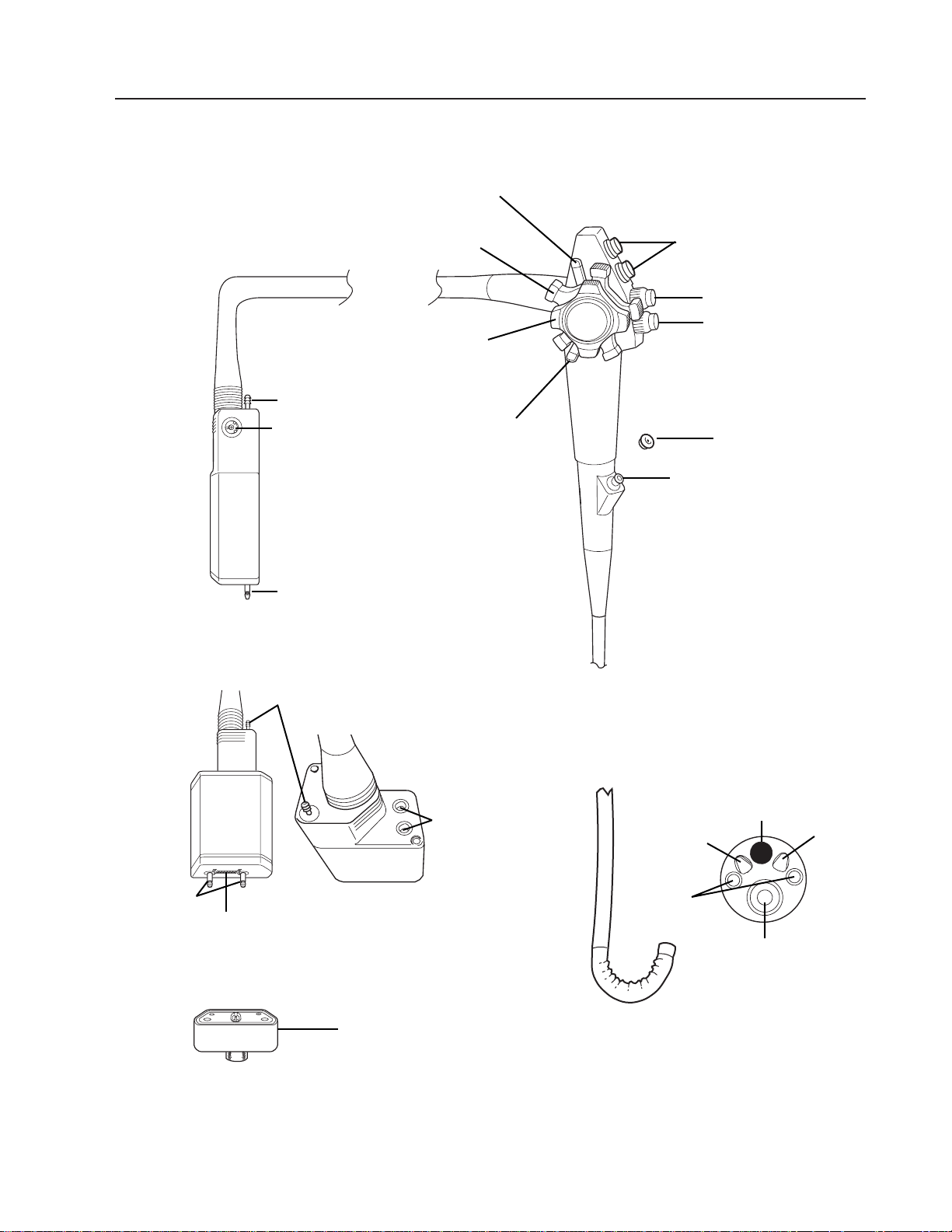
Nomenclature and Function
Flexible VideoEndoscope (200 Series)
VideoEndoscope
6 VideoPath
CONTROL BODY
INSERTION TUBE
BENDING SECTION
DISTAL TIP
ENDOSCOPE CONNECTOR
TERMINAL
Suction Valve
Air/Water Valve
Biopsy Seal
Biopsy Port
Up/Down Deflection
Control Knob
Air
Nozzle
Light
Guides
Biopsy/Suction
Channel
Objective Lens
Water
Nozzle
Suction Port
Side View
Rear/Top View
Front/Bottom
View
Soaking
Cap
ETO/Shipping Vent
Electrical Contacts
Air/Water
Input Ports
Suction Port
Right/Left
Deflection
Control Knob
Light Guide
Light
Guides
Function Control
Switches
Right/Left
Deflection
Control Brake
Up/Down Deflection
Control Brake
Page 9

Nomenclature and Function (continued)
Flexible VideoEndoscope
CONTROL BODY
Suction Valve – Depress to aspirate fluids or air through the biopsy/suction channel.
Air/Water Valve – Covering the vent hole in the top of the valve delivers pressurized air
through the air nozzle in the distal tip. Covering the hole and fully depressing the valve
delivers pressurized water through the water nozzle in the distal tip.
Biopsy Seal – Allows passage of accessories while preventing escape of fluids and air.
Biopsy Port – For introduction of biopsy forceps and other accessories.
Up/Down Deflection Control Knob – Rotation of the knob toward the operator will deflect
the bending section up. Rotation away will deflect the bending section down.
Right/Left Deflection Control Knob – Rotation of the knob toward the operator will
deflect bending section left. Rotation away will deflect the bending section right.
Up/Down Deflection Lock – When this lever is in the “F” (Free) position (rotated fully clock-
wise) the bending section moves freely. When the brake lever is rotated counterclockwise,
deflection of the bending section becomes progressively more stabilized. When the lever is
rotated fully counterclockwise, the bending section is locked into position. Note that when the
lock is engaged, deflection can still be accomplished by rotating the deflection lever.
Right/Left Deflection Lock – Function similarly to Up/Down lock.
ELECTRONIC FUNCTION CONTROLS (when connected to video printer with built-in memory).
F (Freeze) Button – Push to freeze an image.
C (Copy) Button – Push to activate the remote video printer.
V (Video) Button – Push to switch between “frozen” image (stored in printer memory) and
“live” image.
INSERTION TUBE – Contains random light guides, biopsy/suction channel, air and water
lines, steering cables and wires from CCD (Charge Coupled Device).
BENDING SECTION – Contains articulating vertebra that allows deflection in two planes.
DISTAL TIP
Air Nozzle – Directs pressurized air across objective lens to remove moisture and to
distend cavity being examined.
Light Guides – Provide illumination of examination area.
Biopsy/Suction Channel – Opening from which biopsy forceps and other accessories exit
and where fluid/debris is aspirated when the suction valve is depressed.
Objective Lens – Contains the lens system that provides depth of field and field of view.
Water Nozzle – Directs pressurized water, via the water nozzle, across objective lens to
remove debris.
ENDOSCOPE CONNECTOR TERMINAL
Air/Water Input Ports – Couples with the air/water bottle to allow the introduction of
pressurized air and water to the instrument.
Suction Port – Port where the auxiliary suction machine hose is attached to the
instrument.
Soaking Cap – Covers electrical contacts during immersion (cleaning/disinfection).
Electrical Contacts – Provides power to the endoscope and provides pathway for video
signal input into the light source.
ETO/Shipping Vent – Vent where ETO/Shipping Vent Cap couples to equalize instru-
ment’s internal pressure with room pressure during shipping and ETO gas sterilization.
Light Guides – Couple to lamps in light source to provide illumination.
VG-200 Gastroscope 7
Page 10
Nomenclature and Function (continued)
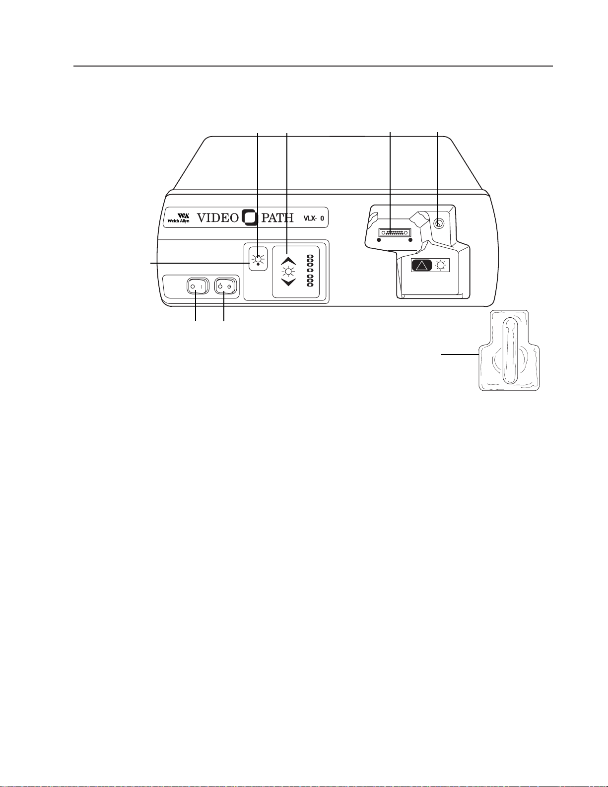
Light Source
Front Panel
Main Power Switch – Primary power control for the light source. If not activated, other
controls will not function.
Air Pump Switch – Activates flow of air at air output connector in light source’s endoscope
connector port.
Lamp Ignition – Activates the lamps when switch is depressed and main power switch
is on.
Lamp Standby Indicator – When LED blinks, lamps cannot be ignited even if lamp igni-
tion switch is depressed.
Endoscope Connector Port – Accepts VideoEndoscope connector terminal to transmit
light, electrical signals, water, and air through the endoscope.
Water Bottle – Couples to endoscope connector terminal’s air and water input ports and
light source’s air output port.
Air Output Port – Couples to water bottle to provide air and water to the endoscope.
Picture Brightness Control – Pressing up or down arrows adjusts image on monitor to
desired average brightness level (level indicated by illuminated green LED).
8 VideoPath
POWER AIR
!
STANDBY
LAMP
IGNITION
LAMP
SERVICE
PICTURE
BRIGHTNESS
2
Main
Power
Switch
Air
Pump
Switch
Lamp
Ignition
Lamp
Standby
Indicator
Endoscope
Connector
Port
Air Output
Port
Picture
Brightness
Control
Water
Bottle
Page 11
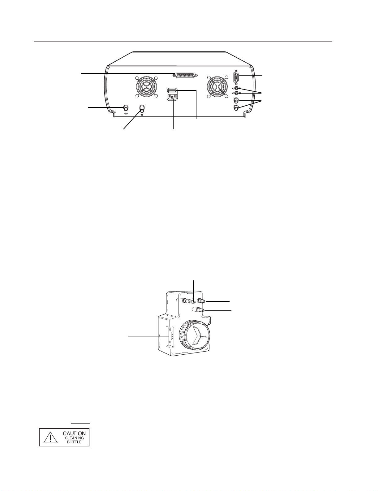
Nomenclature and Function (continued)
Back View
Power Supply Cord Receptacle – Couples with power cord which should be plugged into
an 115V hospital grade outlet.
S-Video – Outputs S-Video or Y/C, 4 pin DIN.
Composite – Outputs NTSC (composite video), BNC connector.
Earth Ground Terminal Connector – Provides a terminal which is connected to earth
ground through the VLX-20 line cord (1/4-36 UNS-2A thread).
Equipotentiality Terminal Connector – Accepts ground connector from electrosurgery
equipment to provide a secondary or redundant ground path.
RS-232 Communication Connector Port – Communication port for use with video printers.
Aux(illiary) Port – No function. Future capability.
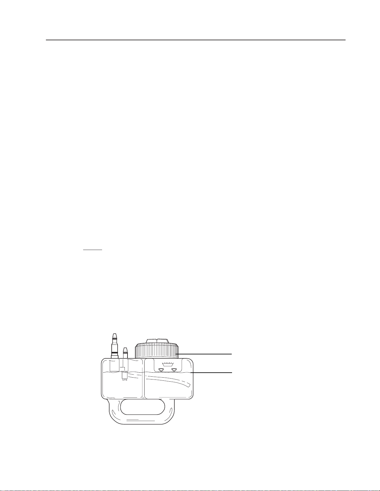
WaterBottle/Cleaning Bottle
Water Bottle
Air Input Terminal – Couples to light source air output port.
Air Output Terminal – Couples to VideoEndoscope air input port.
Water Output Terminal – Couples to VideoEndoscope water input port.
Fill Line – Indicates maximum water level bottle should be filled to.
NOTE
: The cleaning bottle is identical to water bottle with the exception
that it allows fluid to be introduced into the air input port of the
endoscope. The cleaning bottle can be easily identified via the
red caution label on the front of the bottle.
VG-200 Gastroscope 9
Fill Line
Air Input
Terminal
Air Output Terminal
Water Output Terminal
S-Video
Power Supply
Cord Receptacle
Composite
Earth Ground
Terminal Connector
Equipotentiality
Terminal Connector
RS-232
Communication
Connector Port
Fuse Drawer
Auxilliary Port
Page 12
Preparation and Inspection for Use
Prior to Initial Use
Before preparation or set up of the equipment, check all components received against
the list of components (see components section) to verify a complete set. If parts are
missing, please notify Welch Allyn. Review the nomenclature, set-up, operation, and
cleaning/disinfection sections to become familiar with the equipment.
Specifically, inspect:
Video Endoscope
Insertion Tube – for tears, cuts, dents, bubbles, bumps
Control Section – depress valves and test bending section deflection to assure smooth
rotation of controls.
Biopsy Port – pass cleaning brush through biopsy/suction channel to verify
smooth passage
Leak Test – the watertight integrity of the instrument should be verified following the
procedures outlined on page 25.
Light Source
Cabinet – for any dents, scratches or other abnormalities
Water Bottle – for any cracks, leaks, etc.
System Set-up
NOTE: The instrument should be cleaned and disinfected prior to initial
use, following the steps starting on page 23 and 29.
1. Connect the power cord to the power cord receptacle on the back of the light source.
2. Plug the remaining end of the power cord into a properly grounded 100-240 volt AC
outlet.
3. Fill the water bottle to the fill line with clean, distilled water and replace the sealing cap.
10 VideoPath
Fill Line
Sealing Cap
Page 13
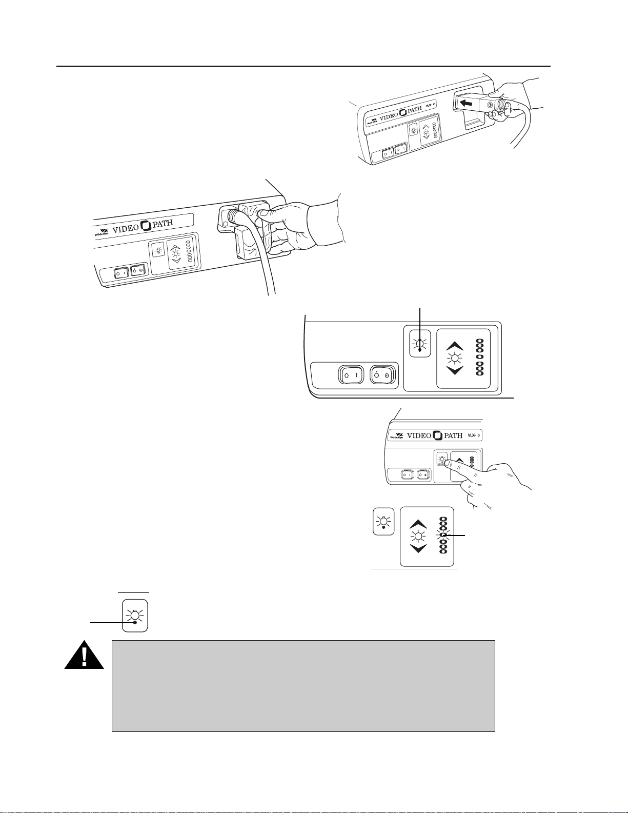
Preparation and Inspection for Use (continued)
4. Plug the endoscope connector terminal into the
endoscope connector port of the light source.
The endoscope connector terminal should fully
engage and “click” into place.
5. Plug the water bottle into the
recessed area on the front panel
of the light source. This will couple
the water bottle both to the light
source air output port and the
VideoEndoscope connector
terminal air/water input ports.
6. Activate the Power switch on the
front panel. The green Lamp
Ignition/Stand-By light will blink for
approximately 11 seconds. Once the
LED stops blinking, the lamps are
ready to be ignited.
7. Once the green Lamp Ignition/Standby light remains
lit, press the Lamp Ignition Switch. The lamps will
ignite and the Lamp Ignition/Standby light will go
out. The lamps require 11 seconds to warm up. This
length of time will be indicated by the center LED of
the Picture Brightness Indicator, which blinks until
the lamps reach full intensity. Once the Picture
Brightness Indicator remains constant, the lamps are
fully warmed up, and the system is ready for use.
NOTE
: If the Light Source is powered up without having the Video-
Endoscope attached, the lamp ignition Standby LED will remain
blinking and lamp ignition cannot occur.
WARNING: Once lamps have been lit, do not remove the instrument
from the light source without turning the main power switch off or putting the lamps on Stand-By by pressing the Lamp Ignition switch. If
the VideoEndoscope is removed from the light source, avoid looking
directly into the intense light provided by the light source to prevent
damage to your eyes.
VG-200 Gastroscope 11
Standby LED Light
Standby
LED
Center
LED of the
Picture
Brightness
Indicator
VLX-20
LAMP
IGNITION
STANDBY
PICTURE
BRIGHTNESS
LAMP
SERVICE
2
LAMP
IGNITION
PICTURE
BRIGHTNESS
LAMP
SERVICE
LAMP
IGNITION
POWER AIR
STANDBY
LAMP
SERVICE
PICTURE
BRIGHTNESS
LAMP
IGNITION
STANDBY
LAMP
IGNITION
STANDBY
LAMP
SERVICE
POWER AIR
PICTURE
BRIGHTNESS
LAMP
IGNITION
LAMP
SERVICE
2
PICTURE
BRIGHTNESS
Page 14
Preparation and Inspection for Use (continued)
8. Activate the Air switch to verify function of the pump. Air should begin to flow immediately
out of the top hole in the air/water valve on the control section of the instrument.
WARNING: It is essential that the instruction manual for the VLX-20 Light
Source be reviewed in detail prior to using the system.
Physical System Inspection
Before inspecting the system, the VideoEndoscope should be tested to verify that it is watertight. Refer to the Leak Test procedures on page 25.
The following steps should be repeated prior to every procedure to verify that the system is
working properly. If any problem is encountered, immediately consult the troubleshooting section of this manual or contact Welch Allyn Customer Service (1-800-535-6663) for assistance.
Insertion Tube, Umbilical Tube, and Bending Section
N
OTE: The insertion tube may have a slight curve when first removed
from the package due to product settling. This can be eliminated by
storing the instrument with the insertion tube in a straight position.
1. Inspect the insertion tube and bending section for tears, cuts, dents, bubbles, bumps or
other abnormalities on the surface.
2. Run your fingers carefully over the entire length of the insertion tube and bending section
to check for protruding braid.
3. Inspect the umbilical cord for outward indications of damage (e.g., dents, cuts).
CAUTION: To avoid harm to the patient and further damage to the equipment, Do Not use a VideoEndoscope with outward signs of damage.
NOTE
: Make sure the distal end of the instrument is not damaged. The
distal end has an atraumatic non-removable tip. Do Not try to
remove the distal tip. Doing so will result in damage to the distal
portion of the instrument.
12 VideoPath
Page 15
Preparation and Inspection for Use (continued)
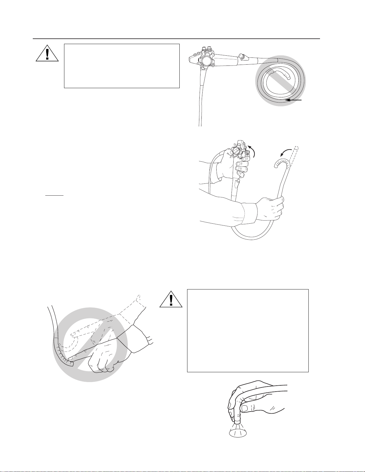
CAUTION: Do Not wind the insertion
tube into a tight radius. Serious
internal damage could result. Proper
storage procedures are outlined
on page 39.
Deflection Controls
1. Rotate the up/down and right/left deflection
control knobs to the limit in each direction.
The knobs should rotate without excess
friction or grinding.
NOTE
: Do Not attempt to rotate the deflection
knobs past their limits. This can result
in severe damage to the steering
mechanism.
2. Make sure the bending section can be
locked into position by engaging the deflection brakes. The brakes are disengaged
when the brake levers are rotated fully clockwise (looking at the steering knobs straight
on). The bending section will move freely. As the brake levers are rotated counterclockwise, the bending section becomes progressively stiffer. When the brake levers are
rotated fully counterclockwise, the bending section is locked into position.
CAUTION: Do Not deflect the bending
section of the VideoEndoscope by
hand. This applies excess force to the
deflection mechanism and may result
in steering cable failure. If the deflection controls do not operate smoothly
do not use the VideoEndoscope. Doing
so may result in injury to the patient or
further damage to the instrument.
Inspection of Light Guides and Optics
1. With the lamps on, hold the distal tip approximately
40mm from any surface.
2. Verify light is being emitted from both light guides.
VG-200 Gastroscope 13
Do Not
Wind
Page 16

Preparation and Inspection for Use (continued)
Inspection of Air Feed Valve
1. Place the tip of the bending section into a container of clear water. Cover the hole in
the top of the air/water feed valve (green ring). Do not depress the valve. Air should
flow freely from the air nozzle in the distal tip of the instrument and the water should
bubble vigorously.
2. Remove your finger from the valve – the bubbling should end immediately.
Inspection of Water Feed Valve
1. Depress the air/water valve completely to initiate the flow of water from the water nozzle
in the distal tip of the instrument. Water should flow in a constant stream over the objective lens and light guides. Upon initial set-up, depress and hold the valve for several
seconds for water to fill the entire line.
NOTE
: If air or water do not flow from the distal tip, refer to the
Troubleshooting section (page 43).
Inspection of Suction Mechanism
1. Connect the suction tubing from the suction machine to the Suction Port hose barb on the
endoscope connector terminal.
2. Immerse the distal tip of the bending section into clear water and completely depress the
suction valve (orange ring). Make sure biopsy seal is in place.
3. Verify aspiration by viewing water flow into suction receptacle. Releasing valve should
stop suction immediately.
14 VideoPath
Cover
Depress
Depress
Suction Port
Page 17

Preparation and Inspection for Use (continued)
NOTE: It is important that the rubber biopsy seal on the biopsy port is in
good condition. Worn seals will result in poor suction and leakage
and should be replaced.
Inspection of Biopsy/Suction Channel
1. Check for kinks in the flexible shaft of the biopsy forceps.
2. Clean any debris from the biopsy forceps before using them.
3. Make sure the handle mechanism on the forceps works
freely and the jaws open and close freely.
4. Close and inspect the jaws of the forceps to make sure the
cups are in proper alignment. If there is a spike in the forceps, make sure the spike is completely straight and within
the cups.
WARNING: It is important that forceps or accessories not be used if they
show any sign of damage or if they do not operate correctly. If the forceps
or an accessory does not work properly during a procedure, serious injury
to the patient could result. Use of damaged forceps or accessories could
also result in damage to the VideoEndoscope.
5. Straighten the VideoEndoscope and insert the forceps through the biopsy port.
If resistance is encountered, contact Welch Allyn Technical Service. Do Not insert
the accessory further. Damage could occur to the instrument. Do Not use the
VideoEndoscope.
Operations
Procedure
The methods and techniques of flexible gastroscopy are well-defined and documented.
Endoscopy training seminars and preceptorship programs are also in existence worldwide.
No attempt is made in this manual to outline the medical procedure or techniques of flexible
gastroscopy. The physician should always take care to understand the clinical background of
each patient and the possible contraindications of the procedure.
Before beginning the procedure, make sure the patient is prepared for the examination using
the normal steps required for endoscopy.
VG-200 Gastroscope 15
Page 18

Operations (continued)
Holding the Instrument
The control section is designed for the left hand. The
“V” formed by the left thumb and index finger should
be positioned beneath the area where the umbilical
cord exits the control section. The suction and
air/water valves are controlled by the index finger and
middle finger respectively. The up/down deflection
control is operated by the thumb. The right hand is
used to advance and rotate (torque) the insertion
tube. In some instances, it may be necessary to have
an assistant hold the insertion tube while the right/left
deflection control is rotated by the right hand.
Preparation Before Insertion of the VideoEndoscope
WARNING: Make sure the VideoEndoscope is properly disinfected or
sterilized prior to every use. Current infection control guidelines require
that VideoEndoscopes and their patient contact accessories be subjected
to high level disinfection or sterilization.
1. Use a clean gauze to gently wipe the insertion tube.
2. Moisten a cotton-tip swab with alcohol and gently
clean the objective lens on the distal tip. If a lens
cleaner (anti-fogging agent) is used, apply it first to
gauze or other applicator. Make sure to wipe off all
excess cleaner.
3. Apply a medical grade water soluble lubricant
(e.g., KY Jelly) to the bending section and
insertion tube. Do Not use petroleum based
lubricants. Do Not contaminate the lens with
lubricant.
16 VideoPath
Lens
Bending
Section
Page 19

Operations (continued)
Insertion and Withdrawal
1. Slowly insert the lubricated instrument.
2. Use the deflection controls to guide the instrument through the lumen. The deflection of
the tip should be done under direct vision in a gentle and deliberate manner.
WARNING: If resistance is encountered, Do Not force the deflection
controls. Doing so may result in serious injury to the patient and/or
damage the instrument.
Do Not advance the instrument if the lumen is not visible. Blind advancement could result in perforation.
If during the procedure, the deflection controls cease to function or the
image is lost due to a power shortage, lamp or processor failure, etc.,
terminate the examination. Return one (or both) of the deflection controls
to the neutral position. Slowly withdraw the VideoEndoscope from the
patient. Do Not operate the controls during withdrawal.
3. A collapsed lumen can be opened by insufflation. Cover the hole on the top of
the air/water valve to insufflate. Adequate distension can be maintained by insufflation
and periodic aspiration of air. Use the suction control to decrease the
level of insufflation.
WARNING: It must be recognized that variations in air flow (pressure
and volume) for patient insufflation may exist from one manufacturer’s
equipment (light source and/or endoscope) to another. It is, therefore,
important to closely monitor the patient at all times and to aspirate
excessive air to prevent over insufflation and patient discomfort.
4. Fluid and secretions can be aspirated by depressing the suction valve, thus improving
visualization. Do Not try to aspirate solid material since this will clog the suction channel.
NOTE
: When using Welch Allyn endoscopes for the aspiration of waste substances,
always follow local waste disposal practices and procedures to minimize
hazards due to contamination.
5. Lubricant and mucous can cloud or fog the objective lens. Use the air/water and
suction control valves alternately to clean the objective lens.
NOTE
: Water drops retained on the lens can be removed by covering the hole on
top of the air/water valve, pushing air through the scope and over the lens.
6. Before removing the VideoEndoscope, aspirate any remaining air to reduce any patient
discomfort.
7. Before withdrawing the scope, return the bending section to the neutral position.
Always withdraw the VideoEndoscope under direct visualization.
VG-200 Gastroscope 17
CAUTION: Care should be taken to avoid sucking mucosa into the
suction channel. This phenomena can result in a “suction polyp” that can
be mistaken for a lesion.
Page 20

Operations (continued)
Biopsy Passage
1. Biopsy forceps and accessories should be inserted through
the biopsy seal and into the channel. Hold the forceps handle so that the jaws are fully closed during insertion.
NOTE
: Failure to insert the forceps in the fully closed
position may cause serious damage to the
biopsy/suction line.
Temporary resistance will be experienced when the cups
are first passed through the seal. Advance the forceps using
short strokes, started by grasping the forceps sheath tightly
at about 5cm from the cups.
WARNING: If resistance is encountered during the passage through the
bending section, relax the deflection angle until the passage is smooth
and easy. Wetting the forceps with water or a medical grade silicone
lubricant will promote easier passage. Never apply excessive pressure
when inserting any accessory into the biopsy channel, since the channel
may be damaged, resulting in malfunction of the VideoEndoscope and
costly repairs.
If the biopsy seal “Splits” or leaks while the VideoEndoscope is in place, remove the
defective seal and replace it.
NOTE
: When replacing the biopsy seal, rotate the
seal one full turn clockwise after pushing on
the luer lock fitting to insure a proper seal.
NOTE
: Always flush the biopsy/suction channel
immediately after a procedure by aspirating
clear water through the channel (see the
Cleaning instructions). This flushing will
assist passage of instruments in
subsequent procedures.
2. Collect a tissue sample by opening the forceps and advancing the open cups up
against the mucosa. Carefully close the cups until resistance is felt, and then hold.
Gently pull back on the forceps until a small tissue sample is removed. Always keep
the accessory in view during advancement.
3. Withdraw the forceps with the cups closed. Opening the cups during withdrawal may
damage the biopsy channel.
18 VideoPath
Page 21

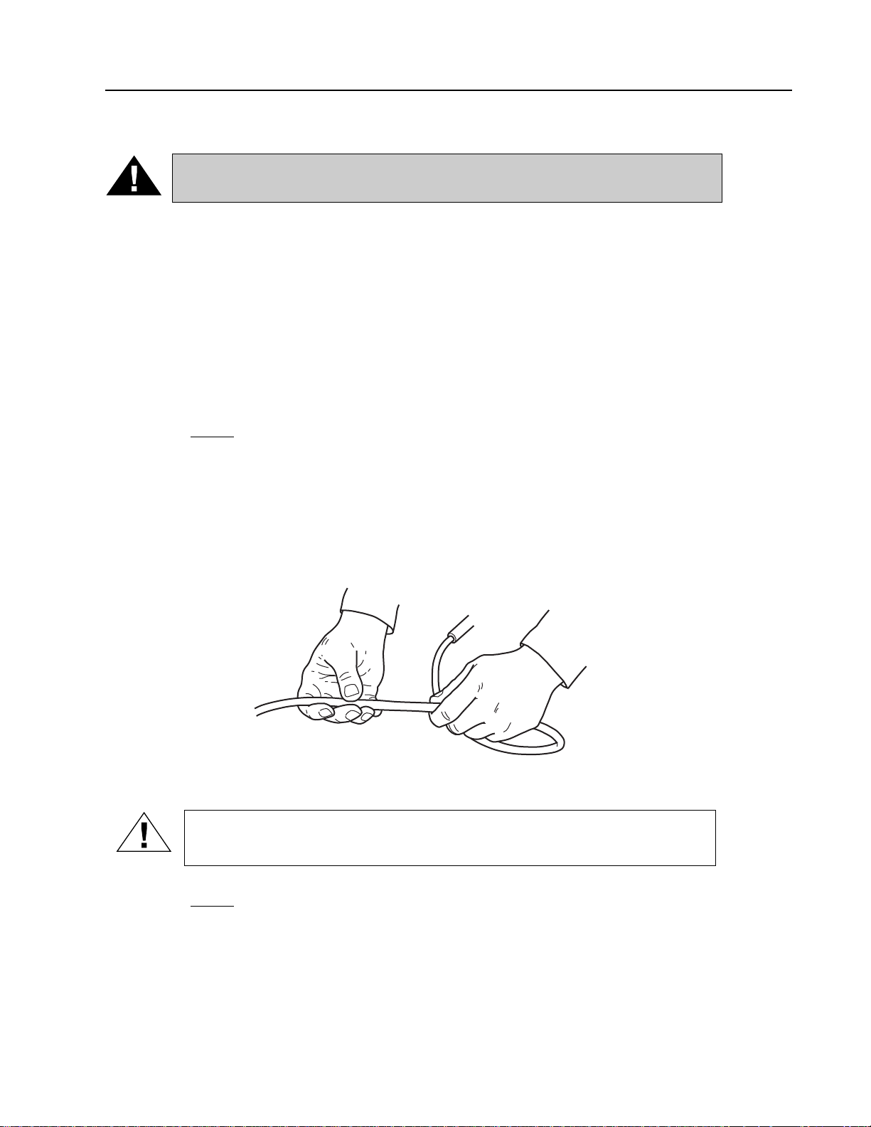
Operations (continued)
NOTE: If the forceps fail to close during a procedure,
close the cups by winding the proximal portion of the forceps cable around your index
finger. If the forceps still do not close, retract
the cups as close as possible to the distal tip
and slowly withdraw the instrument under
direct visualization.
Because of the effect that accessories
used in the biopsy/suction channel of the
VideoEndoscope can have on the performance of the VideoEndoscope itself, it is
strongly recommended that only Welch Allyn
accessories be used with Welch Allyn instruments. If a unique or highly specialized
accessory is available from another source,
please contact Welch Allyn to arrange for a test of its compatibility
before using it through the Welch Allyn VideoEndoscope.
Electrosurgery
The user must carefully read and understand all the instructions in the operating manuals
supplied with the electrosurgical generator and associated accessories. All electrosurgical
equipment must be thoroughly inspected prior to use. Only the user can determine if the
condition of the electrosurgical generator and accessories is correct and safe for clinical use.
1. The electrosurgical accessories should be introduced through the VideoSigmoidoscope
in the same manner as described for the biopsy forceps in the preceding section.
2. The active portion of the electrosurgical accessory should always be clearly visualized
before applying electrical energy to the instrument.
CAUTION: High frequency surgical equipment used with the endoscope
must comply with the IEC 60601-2-2, Particular Requirements for the
Safety of High Frequency Surgical Equipment.
CAUTION: The chassis of the high frequency surgical equipment, if
accessible, should be connected to the Equipotentiality Terminal of the
VLX-20 Light Source to eliminate the potential of RF voltage potential
between the two devices during electrosurgery.
CAUTION: Before use, inspect the insulation of all endoscopic accessories designed for high frequency electrosurgery.
NOTE
: The maximum rated recurring peak voltage of the high frequency generator
used with this endoscope for electrosurgery shall not exceed these limits.
Cut Mode 1000 Volts peak
Coagulation Burst Mode 2000 Volts peak
Coagulation Spray Mode 3000 Volts peak
CAUTION: Avoid using high frequency surgical equipment where
explosive gas concentrations may be in the area of use.
VG-200 Gastroscope 19
Page 22

Operations (continued)
NOTE: The VS-200 Endoscope is Type BF and does not require electri-
cal connection between the endoscope and the neutral electrode
of the high frequency generator during electrosurgery.
Video Printer
The VG-200 VideoEndoscope, when used with the VLX-20 Light Source and compatible
video printer, has the ability to capture, store and print endoscopic images. The function
controls on the endoscope interface with the system for convenient control of the Freeze,
Copy and Video features. The RS-232 Cable must be connected from the VLX-20 Light
Source to the video printer for this feature to perform properly. Please refer to the
Connection Diagrams in the VLX-20 Light Source Instruction Manual for further information. It is important that the user review and understand the instruction manuals associated
with all the components of the system, including the Light Source and video printer.
To save and print an image, perform the following:
F (Freeze) Button – Push and release the button to freeze an image.
C (Copy) Button – Push and release the button to activate the print function.
V (Video) Button – Push and release the button to return to the live image after comple-
tion of the print process. Returning to the live image prior to printing a frozen image will
result in the loss of the frozen image. Please refer to the instruction manual of the video
printer for more detailed instructions.
Cleaning and Disinfection
Endoscope Internal Schematics
These schematic illustrations are intended to provide the user with a better understanding of
how the Welch Allyn VideoEndoscope works. All the internal channels are indicated to better
show their relationship to one another. This understanding should assist the user in caring for
and reprocessing the VideoEndoscope.
The design of VideoEndoscopes and its components allows for efficient and effective cleaning and disinfecting by either manual methods or automated processes prior to patient use.
Standard size luer lock and/or luer-slip fittings are used on the connectors on all cleaning/
disinfecting adapters and scope inlet ports. These locks and fittings easily accommodate
reprocessing devices or systems available from other manufacturers.
As illustrated in the schematics, the cleaning system promotes efficient unidirectional flow of
solution beginning from connections at the endoscope connector terminal, traveling up channels in the umbilical cord to the valve cylinders in the control section, passing through the
channels in the insertion tube and finally exiting nozzles or channel openings at the distal tip
of the scope.
The elimination of multiple branching channels, combined with a direct and straightforward
pathway for solutions to travel maximizes flow efficiency and ensures contact of
disinfectant/sterilant with all internally exposed channel surfaces.
20 VideoPath
Page 23

Cleaning and Disinfection (continued)
WARNING: It is imperative that flexible VideoEndoscopes and other
semi-critical devices be reprocessed such that high level disinfection is
achieved with an EPA registered sterilant/disinfectant. It should be noted
that any endoscope automated reprocessing device or system* must be
cleared for marketing by the FDA via the 510 (k) premarket notification or
PMA approval process.
Only reprocessing solutions/systems satisfying the above conditions and tested and found to
be compatible by Welch Allyn should be used with Welch Allyn products.
*Liquid chemical germicides (disinfectants/sterilants) to reprocess medical devices come under FDA regulation and new products
must, therefore, undergo a 510 (k) premarket notification submission prior to introduction into interstate commerce.
Internal Schematic
NOTE
: Endoscopic instruments should be meticulously cleaned
immediately after each use prior to disinfection or sterilization.
Endoscopes are delicate and will degrade, if not cleaned properly,
due to the effects of digestive contents (e.g., blood, mucous). The
methods outlined on the following pages have been tested and
verified to have no damaging effects. Therefore, it is important to
adhere to these procedures.
VG-200 Gastroscope 21
Valve Reprocessing Cap
Valve Reprocessing Cap
Biopsy Port
From Syringe (under vacuum)
Insertion Tube
Distal Head
Distal Reprocessing Cap
(fluid collects in cap from air and
water lines and is then pulled
through suction line)
Endoscope Connector
Terminal
Cleaning Fluid
Cleaning Bottle
To Suction Container
(suction pump pulls vacuum
on closed system)
Umbilical Tube
Suction Line
Water
Air
Page 24

22 VideoPath
Cleaning and Disinfection (continued)
Required Equipment (for cleaning and disinfection):
Basin of Clean Water
Basin of Enzymatic Solution
Gauze Pads
Disposable Gloves
31020 Channel Cleaning Brush
31021 Valve Reprocessing Caps
31023 60cc Syringes (2 each)
33924 Air/Water Nozzle Cleaning Brush
31027 Reprocessing Adapter
31530 Distal Reprocessing Cap
(semi-automated cleaning only)
31028 Soaking Cap
31037 Leak Tester
33918 Valve Lubricant
31038 Suction Reprocessing Adapter
31031 Valve Well Cleaning Brush
Page 25

VG-200 Gastroscope 23
Cleaning and Disinfection (continued)
WARNING: The importance of meticulous mechanical cleaning of Video
Endoscopes cannot be overemphasized. Prior to disinfection or sterilization, all instruments must be scrupulously cleaned. Failure to do so could
result in incomplete or ineffective disinfection and/or sterilization.
The bending section of the instrument should be handled with care during
the cleaning process. The most common failure that results in an instrument being returned for repair is a leak in the bending section rubber due
to a pin hole leak. Do Not strike the bending section against any hard surface or use abrasive material to wipe clean.
Semi-Automated Cleaning Method
(Utilizing the #45520 Cleaning Bottle)
The following steps should be performed immediately after removal of the instrument from a
patient. For further clarification of the channels affected by this process, please refer to the
internal schematic on page 20.
NOTE
: Protective garments (i.e., gloves, gowns, face masks or shields)
should always be worn during the cleaning process to minimize
the risk of cross contamination.
Cleaning at the Examination Room
Power-off and Wipedown
Remove scope from patient. Turn off suction pump and light source. Leave the scope
plugged into light source and suction tubing attached.
Wipe off insertion tube with enzymatic cleaner and gauze to remove any debris.
Perform Semi-Automated Cleaning Process using enzymatic cleaner.
Note: If for some reason the Semi-Automated Cleaning Process cannot
be performed, refer to the Manual Cleaning Process outlined later
in this section.
Semi-Automated Cleaning Process
Enzymatic Cleaner
See list of approved enzymatic cleaners on page 35.
Remove Water Bottle (45510) from light source. Locate the
Cleaning Bottle (45520) and fill it to the line with enzymatic
cleaner. Dry excess fluid from the exterior of the bottle and
insert it into the light source.
Remove valve plungers and biopsy seal from the scope and
place them in a small container of enzymatic cleaner.
Page 26

Cleaning and Disinfection (continued)
Replace the plungers with the corresponding color-coded Valve Reprocessing Caps (31021).
Attach Distal Reprocessing Cap (31030).
Load a 60cc (31023) syringe with enzymatic cleaner.
Attach to the biopsy port.
Turn on suction
pump. Power up
the light source
and turn on the air
pump. Run until
no enzymatic
cleaner remains in
the cleaning bottle. Empty the suction pump collection bottle periodically throughout the procedure.
When completed, turn off the light source and then
the suction pump.
Disconnect the suction pump tubing from the suction port. Remove the syringe, valve
reprocessing caps and the distal reprocessing cap.
Mechanically Cleaning the Channels
The Channel Cleaning Brush (31020) can now be used to clean the various channels. Insert
the brush into the suction valve well, directing it towards the opening in the
side of the wall which is furthest away from the deflection knobs. Advance
the brush until it exits the suction port on the endoscope connection terminal.
Clean away any debris with a soft, lint-free gauze pad moistened with
enzymatic cleaner and repeat until debris no longer
appears on the brush.
Next, insert the channel cleaning brush into the open
suction valve well and direct it towards the bottom of
the channel. Feed the brush through the opening
until resistance is felt (approx. 15 cm). Do not use
excessive force. Withdraw the brush and clean away
any debris using a gauze pad moistened with enzymatic cleaner.
Repeat the process until debris no longer appears on the brush.
Insert the brush into the open biopsy port and advance
it until it exits from the distal tip of the instrument.
Remove debris from the brush with a gauze pad and withdraw it from the channel. Repeat until no debris appears on the brush.
Insert the Suction Valve Well Cleaning Brush (31031)
into the suction valve well and clean the surface of the
well by rotating the brush while inserting and removing.
Using the Air/Water Nozzle Cleaning Brush (33924),
clean the nozzles at the distal tip of the instrument.
24 VideoPath
Suction
Tube
Distal
Reprocessing Cap
Distal
Reprocessing
Cap
Page 27

Cleaning and Disinfection (continued)
Leakage Testing
Stage 1
Remove the cleaning bottle and scope from the light source.
After making sure that the Leakage Tester (31037) and the ETO vent on the endoscope
connector terminal are dry, attach the leakage tester to the ETO vent. They should be
screwed together until snug to insure a watertight seal.
After making sure that the pressure release valve on the back of the gauge is closed,
(turn fully counter-clockwise) pressurize the inside of the instrument by pumping the
hand bulb until the indicator needle is within the TEST zone. Do not overpressurize
or the scope may be damaged.
Observe the gauge indicator needle. It should remain in the TEST zone for at least one
minute. If it does not remain in the TEST zone, the scope has a leak. Contact the Welch Allyn
Service Dept. immediately before any further processing so that proper steps can be taken to
prevent any damage to the endoscope.
Leakage Testing
Stage 2
If no leaks are determined during the Stage 1 test, the instrument should now be tested for
loss of integrity in the watertight construction due
to small pinholes.
Attach the Soaking Cap (31028) to the endoscope
connector terminal to seal off the electrical contacts. Make sure the leakage tester is securely
attached to the ETO Vent port and that the gauge
indicator needle is still in the TEST zone.
VG-200 Gastroscope 25
T
D
S
A
E
N
T
2
1
2.5
33 22
PSI
G
E
R
3
4
5
S
E
T
2.5
2
1
T
PSI
D
A
N
G
E
R
3
4
5
Page 28

Cleaning and Disinfection (continued)
Immerse the entire instrument, with all
valves and biopsy seals removed, into enzymatic cleaner. Immerse only a small part of
the leakage tester tubing. Never immerse
the entire leakage tester.
Carefully observe the instrument for bubbles
while deflecting the distal tip in all 4 directions. Observe for at least one minute. Afew
bubbles may initially rise from the biopsy
channel or recessed areas of the scope.
This is normal. If bubbles continue to rise
from the same location, a leak is indicated.
Remove the scope immediately from the
basin and contact the Welch Allyn Service
Dept. before any further processing so that
proper steps can be taken to prevent any
damage to the endoscope.
Mechanically Cleaning the Exterior of the Instrument
If the scope has successfully passed the leakage test it should now be cleaned.
Make sure
that the leakage tester remains securely attached to the endoscope light source connector.
While still immersed in the enzymatic cleaner, gently but thoroughly wash the entire exterior
surface of the endoscope with a gauze pad moistened with enzymatic cleaner. In addition,
wash the valves plungers, biopsy seal and reprocessing cap with enzymatic solution.
Clean Water Rinse
Remove the endoscope and accessories from the enzymatic solution and immerse it in a
container of clean water. Rinse all components thoroughly.
After removing the instrument from the water,
open the pressure release valve on the leak-
age tester to release the air pressure. Remove the leakage tester
. Never connect or discon-
nect the leakage tester under water. The instrument will be severely damaged.
Remove the soaking cap from the light source connector.
Semi-Automated Cleaning Process
Clean Water
Refill the cleaning bottle and 60cc syringe with clean water and repeat the Semi-Automated
Cleaning Process as previously described to remove enzymatic cleaner from the channels.
Remove the syringe and the distal reprocessing cap. Leave the valve reprocessing caps in
place. Remove the cleaning bottle and the scope from the light source.
Now proceed with disinfection of the instrument by using Disinfection Procedure (Total
Immersion).
26 VideoPath
Page 29

VG-200 Gastroscope 27
Cleaning and Disinfection (continued)
Disinfection Procedure (Total Immersion)
See the list of approved disinfectants on page 36.
Fill a covered basin with activated disinfectant to a level that will allow the entire instrument
to be immersed in solution.
Connect the Air/Water Reprocessing Adapter (31027) to the air and water ports on the
endoscope connector.
Attach the color-coded valve reprocessing caps.
Attach the soaking cap to the endoscope connector terminal.
Place the entire endoscope into the basin making sure that all surfaces are immersed
in the disinfectant. Place the air/water and suction valves and the biopsy seal into
the solution as well.
Fill a 60cc syringe with disinfectant and attach it to
the air/water reprocessing adapter. Fill another
60cc syringe and attach
it to the biopsy port.
Depress the plungers
of both syringes to
fill all channels with
disinfectant.
Following the solution manufacturer’s recommendations,
allow the instrument to soak for the proper time period.
Air/Water
Reprocessing Adapter
Air/Water
Reprocessing Cap
Suction Reprocessing
Cap
Page 30

28 VideoPath
Cleaning and Disinfection (continued)
Following the disinfection soak cycle ....
Remove the endoscope connector terminal from the disinfectant and uncouple the syringe
from the adapter. Also remove the other syringe. Fill both syringes with air and reattach.
Inject air from both syringes to purge the lines of disinfectant. Repeat until bubbles appear
indicating that all solution has been removed.
Remove the instrument from the solution and uncouple the syringes and the adapter.
Place the entire instrument into a basin or sink of clean water. Thoroughly wipe down the
exterior of the instrument to remove any residual solution. Remove all accessories from the
basin and rinse them thoroughly with clean water.
Proceed to Final Rinse.
Final Rinse
Perform the
Semi-Automated Cleaning Process
, this time using
Clean Water
. Attach the light
guide connector to the light source and follow the steps in the Semi-Automated Cleaning
Process section above, this time using
Clean Water
instead of enzymatic solution.
The Semi-Automated Cleaning Process may be repeated with alcohol, if desired, to promote
drying. Use only 70% Isopropyl alcohol.
Apply a thin coating of Welch Allyn Valve Lubricant (33918) to the Air/Water Valve “O” Rings
(31024) and Suction Valve “O” Rings (31025). Remove air/water and suction caps and insert
the valves into the open valve wells. Reattach the Biopsy Seal (33930) to the biopsy port.
Disconnect the endoscope from the light source and hang it on the Instrument Hanger
(31035) to dry.
Page 31

Cleaning and Disinfection (continued)
Manual Cleaning Method
(Alternative to the Semi-Automated Cleaning Process described above)
Cleaning at the Examination Room
The following steps should be performed immediately
after removal of the instrument from a patient.
NOTE
: Protective garments (i.e., gloves, gowns,
face masks or shields) should always be
worn during the cleaning process to minimize the risk of cross contamination.
Immediately after the instrument is removed from the
patient, put the lamps on stand-by by pressing the lamp ignition switch. Next, wipe off all
debris from the insertion tube with a soft, lint-free cloth moistened with enzymatic detergent.
See page 35 for a list of compatible detergents.
With the instrument still coupled to the suction machine, insert the distal tip into the enzymatic solution and depress the suction valve. Aspirate solution through the biopsy/suction
channel until the solution exiting from the suction port is clean and free of debris. Alternate
aspiration of solution and air for 5-10 seconds.
VG-200 Gastroscope 29
Cover
PICTURE
BRIGHTNESS
2
LAMP
IGNITION
POWER AIR
LAMP
SERVICE
Page 32

Cleaning and Disinfection (continued)
Keeping the distal tip in the container of solution (air switch is still “on”), depress the air/water
feed valve (green valve) for 5-10 seconds. Release the valve and cover the hole on top for
5-10 seconds. This will expel any mucous, debris, etc. which may have entered the air and
water nozzles during the procedure.
Turn off the light source and then the suction pump, and remove the suction line from the
endoscope suction port.
Grasp the water bottle handle and pull
back gently to disconnect the bottle
from the light source.
Detach the endoscope connector terminal from the light source by grasping the
umbilical cord strain relief and pulling
back gently. The instrument is now
ready to be transported to the cleaning
room for further processing.
Mechanically Cleaning the Channels
Remove the valve plungers and biopsy seal from the scope and place them in a small container of enzymatic cleaner. The Channel Cleaning Brush (31020) can now be used to clean
the various channels. Insert the brush into the suction valve well, directing it towards the
30 VideoPath
Cover
Depress
VLX-20
LAMP
IGNITION
STANDBY
PICTURE
BRIGHTNESS
LAMP
SERVICE
Page 33

Cleaning and Disinfection (continued)
opening in the side of the wall which is furthest away from the deflection
knobs. Advance the brush until it exits the suction port on the endoscope
connection terminal. Clean away any debris with a soft, lint-free gauze pad
moistened with enzymatic cleaner and repeat until debris no longer
appears on the brush.
Next, insert the channel cleaning brush into the open suction valve well
and direct it towards the bottom of the channel.
Feed the brush through the opening until resistance is felt (approx. 15 cm). Do not use exces-
sive force. Withdraw the brush and clean away
any debris using a gauze pad moistened with enzymatic cleaner.
Repeat the process until debris no longer appears on the brush.
Insert the brush into the open biopsy port and advance it until it
exits from the distal tip of the instrument.
Remove debris from the brush with a gauze
pad and withdraw it from the channel. Repeat
until no debris appears on the brush.
Insert the Suction Valve Well Cleaning Brush
(31031) into the suction valve well and clean the
surface of the well by rotating the brush while
inserting and removing.
Using the Air/Water Nozzle Cleaning Brush
(33924), clean the nozzles at the distal tip of
the instrument.
Leakage Testing
Stage 1
Remove the cleaning bottle and scope from the light source.
After making sure that the Leakage Tester (31037) and the ETO vent on the endoscope
connector terminal are dry, attach the leakage tester to the ETO vent. They should be
screwed together until snug to insure a watertight seal.
After making sure that the pressure release valve on the back of the gauge is closed,
(turn fully counter-clockwise) pressurize the inside of the instrument by pumping the
hand bulb until the indicator needle is within the TEST zone. Do not overpressurize
or the scope may be damaged.
VG-200 Gastroscope 31
Page 34

Cleaning and Disinfection (continued)
Observe the gauge indicator needle. It should remain in the TEST zone for at least one
minute. If it does not remain in the TEST zone, the scope has a leak. Contact the Welch Allyn
Service Dept. immediately before any further processing so that proper steps can be taken to
prevent any damage to the endoscope.
Leakage Testing
Stage 2
If no leaks are determined during the Stage 1
test, the instrument should now be tested for
loss of integrity in the watertight construction
due to small pinholes.
Attach the Soaking Cap (31028) to the endoscope connector terminal to seal off the electrical contacts. Make sure the leakage tester is
securely attached to the ETO Vent port and
that the gauge indicator needle is still in the
TEST zone.
Immerse the entire instrument, with all valves
and biopsy seals removed, into enzymatic cleaner. Immerse only a small part of the leakage
tester tubing. Never immerse the entire leakage
tester.
32 VideoPath
T
D
S
A
E
N
T
G
E
R
3
2.5
2
4
33 22
1
5
PSI
T
D
S
A
E
T
2.5
2
1
N
G
E
R
3
4
5
PSI
Page 35

Cleaning and Disinfection (continued)
Carefully observe the instrument for bubbles while deflecting the distal tip in all 4 directions.
Observe for at least one minute. Afew bubbles may initially rise from the biopsy channel or
recessed areas of the scope. This is normal. If bubbles continue to rise from the same location, a leak is indicated. Remove the scope immediately from the basin and contact the
Welch Allyn Service Dept. before any further processing so that proper steps can be taken to
prevent any damage to the endoscope.
Mechanically Cleaning the Exterior of the Instrument
If the scope has successfully passed the leakage test it should now be cleaned.
Make sure
that the leakage tester remains securely attached to the endoscope light source connector.
While still immersed in the enzymatic cleaner, gently but thoroughly wash the entire exterior
surface of the endoscope with a gauze pad moistened with enzymatic cleaner. In addition,
wash the valves plungers, biopsy seal and reprocessing cap with enzymatic solution.
Enzyme Cleaning the Channels of the Instrument
Connect the Air/Water Reprocessing Adapter (31027) to the air and water ports on the
endoscope connector.
Attach the color-coded valve reprocessing caps.
Attach the soaking cap to the endoscope connector terminal.
Fill a 60cc syringe with enzymatic cleaner and attach it to the air/water reprocessing adapter.
Fill another 60cc syringe and attach it to the biopsy port.
Depress the plungers of both syringes to fill
all channels.
Following the solution manufacturer’s recommendations, allow the instrument to soak for the
proper time period.
VG-200 Gastroscope 33
Air/Water
Reprocessing Adapter
Air/Water
Reprocessing Cap
Suction Reprocessing
Cap
Page 36

Cleaning and Disinfection (continued)
Following the soak cycle, remove the instrument from the solution and place into a sink or
basin filled with clean water, along with the air/water, suction valves and biopsy seal.
Rinse the exterior of the instrument (including valves and seal) thoroughly to remove any
residual solution.
Lift the endoscope connector terminal out of the basin and remove the syringe coupled to
the air/water reprossessing adapter. Refill the syringe with clean water and reattach. Inject
clean water into the air and water lines to rinse. Continue until the water exiting from the air
and water nozzles is clear.
Remove the syringe connected to the biopsy port and fill with clean water. Reconnect and
inject water until it sprays from the open biopsy/suction channel and the suction port.
Continue until the water exiting from channel and port is clear.
WARNING: Make sure that ALL internal channels (e.g., air, water,
suction), the outside of the instrument, and components are thoroughly
rinsed with clean water to remove any remaining enzymatic detergent
solution.
Uncouple both syringes. Fill with air, recouple and inject air through the lines to dry. Repeat
until water does not exit from the channels.
Lift the entire instrument out of the clean water and place on a clean, dry towel to dry
(valves and biopsy seal, as well).
Gently dry the outside surfaces of the instrument with a soft, clean, lint-free cloth. Dry the
objective lens with a cotton-tipped applicator. Open the pressure release valve on the
leakage tester to release the air pressure. Remove the leakage tester. Never connect or
disconnect the leakage tester under water. The instrument will be severely damaged.
NOTE
: 70% alcohol, followed by air may be introduced through the
channels to promote drying.
The instrument is now ready to be disinfected.
34 VideoPath
Page 37

Cleaning and Disinfection (continued)
Enzymatic Cleaning Solutions
NOTE: Specific references to brand name is not an endorsement of
efficacy as a cleaning solution. Tests have shown these solutions
to be compatible with Welch Allyn endoscopes, providing the
manufacturer’s directions are followed.
The materials listed below are considered safe for use with the Welch Allyn
VideoEndoscope if used according to the manufacturer’s instructions for cleaning
and in accordance with procedures detailed in the cleaning section of this manual.
Brand Name Source Usage
Endozime The Ruhof Corp.
Klenzyme Calgon Vestal Labs Follow
Enzy-Clean Burnishine Products Manufacturer’s
Metrizyme Metrex Research Corp. Instructions
Enzol J & J Medical
These solutions must be enzymatic detergents or other cleaning agents specially
formulated to clean endoscopes.
WARNING: Before disinfection or sterilization, be sure that any enzymatic
cleaning solution is thoroughly rinsed off all surfaces. Cleaning solutions
should not be combined with disinfecting or sterilizing solutions since they
can alter the germicidal effectiveness.
Cleaning of Accessories – Biopsy Forceps
1. Clean reusable forceps immediately after each use since dried blood, mucous, or other
debris may cause damage and make it impossible to use the forceps. If forceps are not
clean prior to sterilization, the user may not be able to reprocess them properly.
2. Place the forceps in a container of warm water and enzymatic detergent. Do Not tightly
coil or kink the flexible shaft.
3. Clean the handle and flexible shaft with a soft, clean cloth. Carefully and gently clean the
biopsy cups, pivot pin, and needle with a soft brush.
4. Rinse any remaining detergent from the forceps by rinsing the entire forceps with clean
water while manipulating the handle and biopsy cups mechanism.
VG-200 Gastroscope 35
Page 38

Cleaning and Disinfection (continued)
NOTE: Make certain all detergent is removed from the inner mechanism
of the forceps. Any remaining detergent after the water evaporated causes increased friction that may cause the mechanism not
to work. Any remaining detergent also may interfere in the subsequent sterilization process.
5. After the forceps are cleaned and thoroughly rinsed, dry them gently with a soft, clean lint
free cloth. Do not tightly coil or kink or put tension on the flexible shaft of the forceps.
NOTE
: Clean all other reusable accessories (e.g., channel cleaning
accessories, cleaning brushes) and scope components (e.g.,
rubber biopsy seals, air/water and suction control valves) in the
same way as the forceps were cleaned.
High-Level Disinfection
The Welch Allyn VideoEndoscopes are manufactured from a variety of special materials
which optimize the instrument’s performance, but may not withstand some disinfection solutions and methods.
Prior to disinfection, the instrument should be thoroughly cleaned and dried following the
methods previously discussed. Incomplete or improper cleaning will decrease the effectiveness of the disinfection process.
CAUTION: Before complete immersion in any disinfecting solution,
make sure the instrument has been leak tested. Refer to instructions
on page 31.
Disinfecting Solutions
NOTE: Specific references to brand name is not an endorsement of
efficacy as a disinfecting solution. Tests have shown these solutions to be compatible with Welch Allyn endoscopes, providing
the manufacturer’s directions are followed.
The materials listed below are considered safe for use with the Welch Allyn flexible VideoEndoscope if used according to the manufacturer’s instructions for cleaning and in accordance with procedures explained in the disinfecting section of this manual.
Solution Brand Name Source Usage
Cidex (14 day) (2.4%) J & J Medical
Follow
Glutaraldehyde Wavicide-01 (2.5%) Wave Energy System Inc.
Manufacturer’s
Metricide (14 day) (2.6%) Metrex Research Corp.
Instructions
36 VideoPath
Page 39

Cleaning and Disinfection (continued)
NOTE: Do not use any other solutions until a sample has been sent to
Welch Allyn for compatibility testing.
Refer to the infection control note located on the inside cover of
the manual.
CAUTION: Before immersing the scope, remove the ETO/Shipping vent
and place the soaking cap on the electrical contacts located on the endoscope connector terminal.
For clarity the reader may wish to refer to the internal schematic on
page 21 showing the pathways involved during the disinfection process.
Sterilization and Aeration
Before sterilizing the instrument make certain to thoroughly follow the cleaning instructions in
the cleaning section of this manual. It is up to the user to determine if the sterilization procedures described in this section meet the requirements of the facility.
CAUTION: NEVER put the instrument in a steam autoclave.
Ethylene Oxide Gas Sterilization
If Ethylene Oxide (ETO) Gas sterilization is performed on this instrument, make sure to follow
the steps below. This is an acceptable method of sterilization for this instrument, however the
steps are different from those used for other endoscopes.
1. Properly clean and dry the instrument according to the instructions presented previously
in this manual. Remove all component parts (e.g., air/water valve, suction valve, biopsy
seal, etc.).
VG-200 Gastroscope 37
Page 40

Cleaning and Disinfection (continued)
WARNING: If all surface areas are not completely dried, the ETO gas
may not make contact with the contaminated surfaces, causing incomplete or ineffective sterilization.
Important: Before placing the instrument in a gas sterilizer or aeration chamber, be sure to:
• Couple the Shipping/ETO vent to the ETO vent on the endoscope connector terminal.
• The soaking cap (Part No. 31028) should not be attached and must be OFF of the
electrical contacts.
WARNING: Failure to attach the Shipping/ETO Vent Cap will result in
severe damage to the instrument.
NOTE
: This is the opposite procedure from the immersion instructions.
• Make sure the temperature does not exceed 55°C (131°F).
• Make certain the pressure does not exceed 24 psi.
• Make sure the humidity does not exceed 70%.
• Make certain the sterilization procedure does not exceed
4 hours.
2. After ETO Gas sterilization, 72 hours of aeration at room temperature must follow. The
aeration time may be shortened to 12 hours if an aeration chamber is used. The temperature must not exceed 55°C (131°F).
Cold Sterilization
If Ethylene Oxide (ETO) Gas sterilization is not available, the Welch Allyn VideoEndoscope
can withstand immersion in glutaraldehyde solution for a maximum of 12 hours to achieve
cold sterilization. Before fully immersing the instrument, perform the leakage test described in
the Leakage Testing section.
CAUTION: NEVER IMMERSE THE ENDOSCOPE FOR MORE THAN
12 HOURS. After the 12 hours, thoroughly rinse the instrument to remove
all of the glutaraldehyde solution.
After rinsing the instrument, attach the Shipping/ETO Vent to balance the internal and external humidity.
Other Sterilization Methods
CAUTION: While there are other types of cleaning and/or sterilization
systems or processes available, these types may have damaging effects
on the instrument because of the heat sensitive nature and/or the specific
biocompatible materials used in construction of the endoscopes.
38 VideoPath
Page 41

VG-200 Gastroscope 39
Cleaning and Disinfection (continued)
To avoid damage to the instrument, check the compatibility of reprocessing systems/
processes other than described in this manual with your Welch Allyn representative.
Accessory Sterilization
WARNING: According to current infection control guidelines all acces-
sories that break the mucosal barrier (e.g., biopsy forceps), must be
sterilized.
Before sterilizing the accessories, make certain to thoroughly follow the cleaning instructions
in the Cleaning Section of this manual. It is up to the user to determine if the sterilization procedures described in this section meet the requirements of the facility.
1. Once the accessories have been cleaned and thoroughly dried, Ethylene Oxide (ETO)
Gas sterilization can be performed.
2. Aeration is necessary after the accessories have been subjected to ETO sterilization.
Accessory and Instrument Storage
1. Make sure all water is removed from the instrument and accessories.
2. Store the instrument with the insertion tube and umbilical cable as straight as possible. If
coiling is necessary, the insertion tube and umbilical cable should not be wound in more
than one loop.
3. Do Not store the instrument in an area exposed to temperature extremes, high humidity, or
direct sunlight. The storage area should be dry and clean.
4. Apply silicone oil to the cups of the biopsy forceps to prevent rust.
5. Couple the Shipping/ETO vent to the instrument to balance the internal and external
humidity. Before storing, remove all valves, biopsy seals, soaking caps, etc. to allow
thorough drying of internal parts.
WARNING: Prior to storage, it is important that no residual water be left
within any internal channels/lumens of the instrument or accessories.
Thoroughly dry all instrument surfaces to reduce the potential for bacteria
colonization during storage.
6. Use optional Welch Allyn wall hanger to store instrument securely (#31035).
NOTE
: This equipment contains no hazardous materials and can be dis-
posed after its useful life without any environmental risks.
CAUTION: Avoid crushing or puncturing any video monitor due to risk of
CRT implosion. Consult your local waste authority for safe disposal.
Page 42

Servicing
Prior to returning any instrument for repair to Welch Allyn, the instrument should first undergo
appropriate reprocessing/decontamination procedures for the purpose of infection control.
1. All instruments requiring repair should be shipped in the original shipping package with
appropriate packing along with comments describing the instrument damage and complaint.
2. A repair/return authorization number, contact name and phone number of the individual
responsible for authorizing repairs, as well as shipping address should be included.
3. The ETO/Shipping vent should be attached to the instrument if it will be shipped by air
freight.
4. Any accessories potentially related to the scope damage or complaint also should be
included with the VideoEndoscope.
5. Soaking caps (if applicable) also should be returned with the VideoEndoscope to
check/confirm the integrity of their watertight seal.
NOTE
: Instrument repairs should only be performed by an authorized
Welch Allyn service facility. Welch Allyn assumes no liability for
any patient/user injury, instrument damage or malfunction, or
reprocessing failure due to repairs made by unauthorized
personnel.
Customer Service Telephone Assistance: 1-800-535-6663
For repairs, ship to:
Welch Allyn Repair Department
4341 State Street Road
Skaneateles Falls, NY 13153
40 VideoPath
Page 43

Care and Maintenance Tips
Flexible endoscopes have been an invaluable tool in the medical community’s armamentarium
to successfully diagnose and treat a wide variety of illnesses in patients for several decades.
Perhaps due to their longevity and progressive design changes over the years which have simplified their use, flexible endoscopes have been somewhat taken for granted and have erroneously not been considered highly technological medical devices.
In fact, current generation flexible endoscopes, although easier to clinically use, are more
sophisticated than ever. Special reprocessing instructions must be followed to make sure the
instruments are patient ready and patient safe. Special care and handling must be exercised
and practiced to prevent instrument malfunction and prolong the reliability of the endoscope.
The burden of responsibility to make sure of safe and reliably functioning instruments is left
in the hands of the healthcare professionals who actually care for and reprocess flexible
endoscopes.
Naturally, equipment manufacturers share this responsibility and tremendous efforts have been
spent in designing instruments which could be reprocessed and maintained as easily as possible. However, due to the nature of their use and application, flexible endoscopes must be subjected to special cleaning procedures, followed by a disinfection or sterilization process after
each and every patient use.
To highlight and simplify what may appear to some as being complicated maintenance
and reprocessing instructions, Welch Allyn strongly recommends that users review the
following suggestions and advice on the care and maintenance of your Welch Allyn flexible
VideoEndoscope.
These tips, particularly those involving scope reprocessing, should not be construed as “shortcuts” and are not intended as substitute directions for complete instructions found elsewhere in
the owner’s manual.
• Avoid soaking of the instrument with accessories (e.g., forceps, injection or aspiration needles) or any sharp-edged objects which could inadvertently scratch or cut the distal bending
section sheath. (Subsequent flexing back and forth of the rubber sheath could eventually
stretch the scratched rubber until a pinhole appears and leak develops.)
• Exposure to a compatible enzymatic detergent is essential to thorough cleaning of all surfaces of the instrument. Rinsing and drying after cleaning is imperative to prevent dilution of
the disinfectant/sterilant.
• Do not reuse disposable accessories intended for single patient or one-time use.
• Do not expose the instrument or accessories to harsh chemical solutions. Strictly adhere to
exposure times recommended by the manufacturers of compatible solutions.
• Avoid contact of any flexible portion of the instrument with any sharp objects (e.g., bed
frames, table top corners, sink drains, accessories hanging in storage cabinets) at any time
during the handling, reprocessing, or storage of the instrument.
• Avoid stretching of the bending section rubber sheath at the distal portion of the scope.
During mechanical cleaning of the instrument with a dampened gauze, do not use excessive force. Agentle back and forth wiping motion should be sufficient to remove gross
debris. Subsequent soaking in an enzymatic detergent will clean the remainder of the
debris.
• Disinfectants and sterilants are toxic substances by nature. All residual solution must be
thoroughly rinsed and dried prior to each patient use.
• The key to preventing clogged air or water channels/nozzles is to immediately flush the
channels upon removal from the patient. This should be followed by soaking with an enzymatic detergent.
VG-200 Gastroscope 41
Page 44

Care and Maintenance Tips (continued)
• Avoid attempting to remove or unscrew the instrument’s components which should not be
removed. Parts such as the distal portion on the end of the bending section and any rubber
strain reliefs on either the insertion tube or umbilical cord are essential to the watertight
integrity of the instrument. Removal or loosening of these components and subsequent
immersion could lead to fluid invasion into the instrument.
• Avoid excessive and/or tight bends in the insertion tube and umbilical cord. Tight curling of
these portions of the instrument can result in serious internal damage.
• Never articulate the bending section by applying force directly to the bending section. This
can cause serious damage to the internal steering cables.
• If resistance is felt during rotation of the deflection control knobs, do not apply excess force.
• Check for any sharp edges on all surfaces of an automated cleaning/reprocessing unit
which may come in contact with an endoscope. Some units may have sharp edged wire
mesh filters and baskets or inlet/outlet ports which could damage the instrument.
• The air/water and suction control valves must be screwed down onto their respective
cylinders on the instrument’s control body to function properly. This is unlike other
manufacturer’s semi-disposable valves with a rubber base which do not have threads to
secure attachment.
• Do NOT overtighten the cap to the water bottle assembly. Overtightening could cause the
cap to crack.
• Do NOT introduce air bubbles into the instrument’s internal channels during flushing of
cleaning and/or disinfecting/sterilizing solutions since the bubbles could interfere in the
effectiveness of the disinfection/sterilization process.
• Do NOT store the instrument and accessories in the carrying case since this type of dark,
humid, and unventilated environment is conducive to bacteria colonization which increases
the risk of cross-contamination.
• Prior to each use, check the condition of all accessories.
Do NOT use any accessories with kinked or bent flexible shafts.
Do NOT use forceps with misaligned cups and/or bent needles/spikes.
Do NOT use aspiration or injection needles which are not retractable or whose sharp tips
cannot be protected.
DO NOT use cleaning brushes without smooth or rounded distal tips.
Use of any of the above accessories could result in channel damage and costly repairs.
• Verification of the effective concentration of glutaraldehyde (via test strips or similar methods) is recommended to ensure potency of glutaraldehyde to achieve high-level disinfection.
• Instrument repairs should be performed by an authorized Welch Allyn service facility.
Welch Allyn assumes no liability for any patient/user injury, instrument damage or malfunction, or reprocessing failure due to repairs made by unauthorized personnel.
42 VideoPath
Page 45

Troubleshooting
Symptom Possible Cause Solution
No image. Endoscope not properly Advance endoscope connector
plugged in. terminal into light source until it
“clicks” into place.
Image is not clear. Distal objective lens obscured. Rinse lens by injecting water
through auxiliary water inlet.
Lenses dirty. Remove endoscope and clean
distal objective lens with cotton
swab and alcohol.
Water damage to lens. Return to Welch Allyn for evalu-
ation/repair.
Inadequate suction. Suction valve blocked. Remove valve, clean valve and
housing with a cleaning brush.
Lubricate “O” rings with valve
lubricant and replace.
Biopsy seal is worn. Replace biopsy seal.
Suction channel blocked. Call Welch Allyn Service
Department for instructions.
Suction pump not on or tubing Verify good connection between
disconnected. suction pump and endoscope.
Turn pump on.
No insufflation. Air pump not turned on. Turn air pump on. Test endo-
scope for air flow.
Water bottle not connected Verify water bottle is properly
properly to light source or plugged into light source.
endo connector plug.
Air nozzle blocked. Soak tip of endoscope in warm
soapy water for 2-3 minutes.
Gently brush with air/water noz-
zle cleaning brush. Gently inject
warm water through the endo-
scope by depressing the
air/water feed valve. If the noz-
zle remains blocked, contact
Welch Allyn Customer Service.
Water bottle cap not Tighten cap.
secured tightly.
Cannot irrigate. Water bottle empty. Fill water bottle to fill line.
Water bottle not connected Verify water bottle is properly
properly to light source or plugged into light source.
endo connector plug.
Water bottle cap not Tighten cap.
secured tightly.
VG-200 Gastroscope 43
Page 46

Troubleshooting (continued)
Symptom Possible Cause Solution
Distal tip will not return to Deflection lock lever either Rotate deflection lock lever
‘neutral’ position. partially or fully engaged. until distal tip can freely
return to ‘neutral’ position.
Suction or Air/Water Dirty valve stem. Remove valve; clean valve and
valve sticks. housing with cotton swab and
alcohol; lubricate “O” rings with
valve lubricant and replace.
Bad “O” rings. Replace “O” rings.
Biopsy seal “spitting” Biopsy seal is worn. Replace biopsy seal. or leaking.
Insufficient articulation Loose articulation knob. Return endoscope to of tip. Welch Allyn for adjustment.
Degree of articulation is less Return endoscope to
than specified. Welch Allyn for adjustment.
Inadequate illumination. Light source not turned on. Turn on power to light source.
Damage to light transmitting Return endoscope to
fibers. Welch Allyn for
evaluation/repair.
Light source not working. Not plugged into electrical Plug light source into 120 volt
outlet. grounded outlet.
Lamps burned out. Replace lamps according to
instructions.
Fuse is blown. Call Welch Allyn Service
Department.
Lamp access plate not
properly re-installed.
No illumination. Endoscope connector plug not
properly engaged.
Electronic Function Controls RS-232 cable not connected Connect RS-232 cable.
do not operate. between VLX-20 Light
Source and video printer.
Video printer not in proper Adjust video printer until
signal input mode. proper input mode is
selected (Composite,
S-Video, RGB).
Printer not adjusted to Set printer to 9600 baud.
proper baud rate.
44 VideoPath
Page 47

Page 48

Welch Allyn, Inc.
4341 State Street Road
P.O. Box 220
Skaneateles Falls, NY 13153-0220
Telephone: 315-685-4560
1-800-535-6663
Printed in the U.S.A. Part # 317531 Rev. A
 Loading...