

Page 1
MicroTymp
MicroTymp
®
3 Handle and
®
Printer/Charger
Service manual
Page 2

Welch Allyn MicroTymp3 Handle and MicroTymp Printer/Charger
REF
© 2009 Welch Allyn. All rights are reserved. No one is permitted to reproduce or duplicate, in any form, this manual or any part
thereof without written permission from Welch Allyn.
Welch Allyn assumes no responsibility for any injury to anyone, or for any illegal or improper use of the product, that may result from
failure to use this product in accordance with the instructions, precautions, warnings, or statement of intended use published in this
manual.
Welch Allyn and MicroTymp are registered trademarks of Welch Allyn.
XP is trademark of Microsoft.
Software in this product is copyrighted by Welch Allyn or its vendors. All rights are reserved. The software is protected by United
States of America copyright laws and international treaty provisions applicable worldwide. Under such laws, the licensee is entitled
to use the copy of the software incorporated with this instrument as intended in the operation of the product in which it is
embedded. The software may not be copied, decompiled, reverse-engineered, disassembled or otherwise reduced to
human-perceivable form. This is not a sale of the software or any copy of the software; all right, title and ownership of the software
remain with Welch Allyn or its vendors.
For information about any Welch Allyn product, call the nearest Welch Allyn representative:
USA + 1 315 685 4560
Canada 800 561 8797 China + 86 216 327 9631
European Call Center + 35 3 46 906 7790 France + 33 1 60 09 33 66
Germany + 49 7477 92 71 86 Japan + 81 3 3219 0071
Latin America + 1 305 669 9003 Netherlands + 31 15 750 5000
Singapore + 65 6419 8100 South Africa + 27 11 777 7555
United Kingdom + 44 20 7365 6780 Sweden + 46 8 58 53 65 51
406695
Material No. 714876 Ver. A
Welch Allyn, Inc.
4341 State Street Road
Skaneateles Falls, NY 13153 -0220 USA
www.welchallyn.com
800 535 6663
Welch Allyn, Ltd.
Navan Business Park
Dublin Road, Navan
County Meath, Republic of Ireland
Australia + 61 2 9638 3000
Page 3

Contents
1 - Introduction and technical overview . . . . . . . . . . . . . . . . . . . . . . . . . 1
iii
About this document . . . . . . . . . . . . . . . . . . . . . . . . . . . . . . . . . . . . . . . . . . . . . . 1
Intended use. . . . . . . . . . . . . . . . . . . . . . . . . . . . . . . . . . . . . . . . . . . . . . . . . . . . . 1
About the device. . . . . . . . . . . . . . . . . . . . . . . . . . . . . . . . . . . . . . . . . . . . . . . . . . 1
Supporting documents and definitions . . . . . . . . . . . . . . . . . . . . . . . . . . . . . . . . . 2
Definitions. . . . . . . . . . . . . . . . . . . . . . . . . . . . . . . . . . . . . . . . . . . . . . . . . . . . . . . 2
Technical overview . . . . . . . . . . . . . . . . . . . . . . . . . . . . . . . . . . . . . . . . . . . . . . . . 3
Controls, indicators, and connectors . . . . . . . . . . . . . . . . . . . . . . . . . . . . . . . . . . 5
Handle components . . . . . . . . . . . . . . . . . . . . . . . . . . . . . . . . . . . . . . . . . . . . 5
Printer/Charger components . . . . . . . . . . . . . . . . . . . . . . . . . . . . . . . . . . . . . 6
Symbols . . . . . . . . . . . . . . . . . . . . . . . . . . . . . . . . . . . . . . . . . . . . . . . . . . . . . . . . 7
General warnings . . . . . . . . . . . . . . . . . . . . . . . . . . . . . . . . . . . . . . . . . . . . . . . . . 9
General cautions . . . . . . . . . . . . . . . . . . . . . . . . . . . . . . . . . . . . . . . . . . . . . . . . . . 9
General notes . . . . . . . . . . . . . . . . . . . . . . . . . . . . . . . . . . . . . . . . . . . . . . . . . . . 10
2 - Testing and verification. . . . . . . . . . . . . . . . . . . . . . . . . . . . . . . . . . . 11
Tools . . . . . . . . . . . . . . . . . . . . . . . . . . . . . . . . . . . . . . . . . . . . . . . . . . . . . . . . . . 11
Bench test and calibration check - Handle . . . . . . . . . . . . . . . . . . . . . . . . . . . . . 13
Purpose of test. . . . . . . . . . . . . . . . . . . . . . . . . . . . . . . . . . . . . . . . . . . . . . . 13
Preparation for test. . . . . . . . . . . . . . . . . . . . . . . . . . . . . . . . . . . . . . . . . . . . 13
Bench test procedures . . . . . . . . . . . . . . . . . . . . . . . . . . . . . . . . . . . . . . . . . 14
Final Tester Setup. . . . . . . . . . . . . . . . . . . . . . . . . . . . . . . . . . . . . . . . . . . . . 17
Testing Performed by the ATE . . . . . . . . . . . . . . . . . . . . . . . . . . . . . . . . . . . . . . 22
Bench test for the Printer/Charger . . . . . . . . . . . . . . . . . . . . . . . . . . . . . . . . . . . 23
Proper powering up of unit. . . . . . . . . . . . . . . . . . . . . . . . . . . . . . . . . . . . . . 23
Proper operation of print head . . . . . . . . . . . . . . . . . . . . . . . . . . . . . . . . . . . 24
Agency tests. . . . . . . . . . . . . . . . . . . . . . . . . . . . . . . . . . . . . . . . . . . . . . . . . . . . 26
Dielectric strength test. . . . . . . . . . . . . . . . . . . . . . . . . . . . . . . . . . . . . . . . . 26
Grounding continuity test. . . . . . . . . . . . . . . . . . . . . . . . . . . . . . . . . . . . . . . 27
Leakage current test . . . . . . . . . . . . . . . . . . . . . . . . . . . . . . . . . . . . . . . . . . 27
3 - Troubleshooting guide . . . . . . . . . . . . . . . . . . . . . . . . . . . . . . . . . . . 29
Handle. . . . . . . . . . . . . . . . . . . . . . . . . . . . . . . . . . . . . . . . . . . . . . . . . . . . . . . . . 29
Printer/Charger . . . . . . . . . . . . . . . . . . . . . . . . . . . . . . . . . . . . . . . . . . . . . . . . . . 30
Noise troubleshooting procedure . . . . . . . . . . . . . . . . . . . . . . . . . . . . . . . . . . . . 31
Leak troubleshooting procedure . . . . . . . . . . . . . . . . . . . . . . . . . . . . . . . . . . . . . 32
Error and service code tables with troubleshooting procedure . . . . . . . . . . . . . 33
Error codes . . . . . . . . . . . . . . . . . . . . . . . . . . . . . . . . . . . . . . . . . . . . . . . . . . 33
Retrieving and clearing error codes . . . . . . . . . . . . . . . . . . . . . . . . . . . . . . . 33
Service codes. . . . . . . . . . . . . . . . . . . . . . . . . . . . . . . . . . . . . . . . . . . . . . . . 34
4 - Disassembly and reassembly. . . . . . . . . . . . . . . . . . . . . . . . . . . . . . 37
Handle. . . . . . . . . . . . . . . . . . . . . . . . . . . . . . . . . . . . . . . . . . . . . . . . . . . . . . . . . 37
Disassembly Procedures . . . . . . . . . . . . . . . . . . . . . . . . . . . . . . . . . . . . . . . 37
Page 4

iv Contents Welch Allyn MicroTymp3 Handle and MicroTymp Printer/Charger
Removal/replacement of the LCD and keypad board assemblies . . . . . . . . 42
Removal/replacement of the power PCBA. . . . . . . . . . . . . . . . . . . . . . . . . . 43
Removal/replacement of the MCU PCBA . . . . . . . . . . . . . . . . . . . . . . . . . . 44
Replacement of Lithium coin battery . . . . . . . . . . . . . . . . . . . . . . . . . . . . . . 45
Proper placement of ESD shields in the back housing. . . . . . . . . . . . . . . . . 45
Printer/Charger . . . . . . . . . . . . . . . . . . . . . . . . . . . . . . . . . . . . . . . . . . . . . . . . . . 46
Removal/replacement of the top panel . . . . . . . . . . . . . . . . . . . . . . . . . . . . 46
Removal/replacement of the main PC board and print head assemblies. . . 47
Removal/replacement of the contact housing and IR flex assemblies. . . . . 48
Removal/replacement of the printer keyboard/LEDs assembly . . . . . . . . . . 49
Removal/replacement of the RFI filter . . . . . . . . . . . . . . . . . . . . . . . . . . . . . 49
Removal/replacement of old main PC board and print head . . . . . . . . . . . . 50
A - Repair parts. . . . . . . . . . . . . . . . . . . . . . . . . . . . . . . . . . . . . . . . . . . . 51
B - Cleaning. . . . . . . . . . . . . . . . . . . . . . . . . . . . . . . . . . . . . . . . . . . . . . . 55
Clean the handle . . . . . . . . . . . . . . . . . . . . . . . . . . . . . . . . . . . . . . . . . . . . . . . . . 55
Clean the printer/charger . . . . . . . . . . . . . . . . . . . . . . . . . . . . . . . . . . . . . . . . . . 55
Clean the probe tips . . . . . . . . . . . . . . . . . . . . . . . . . . . . . . . . . . . . . . . . . . . . . . 55
C - Replacement parts and accessories . . . . . . . . . . . . . . . . . . . . . . . . 57
Page 5

1
Note
1
Introduction and technical overview
About this document
This document is written for technical professionals who are qualified to service medical
instruments. The intended technical environment is any location where service on such
devices is performed. This document describes how to test, calibrate, diagnose,
disassemble, and assemble the MicroTymp3 Handle and MicroTymp Printer/Charger.
Before attempting service on the tympanometer, you must read and understand this
document and all other information that accompanies the tympanometer and its
accessories.
Intended use
This device is an auditory impedance tester intended to detect possible otologic disorders
associated with the functioning of the middle ear.
About the device
Federal US law restricts sale of the device identified in this manual to, or on the order of, a
licensed physician.
Using this device’s 226-Hz and 1000-Hz tympanometry settings, you can quickly and
easily obtain objective results supporting diagnosis of otitis media with effusion and other
middle ear disorders. This information can result in more thorough diagnoses as well as
more effective monitoring, treatment, consultation, and referral.
The 226-Hz test data stored in the memory of the Handle may be printed using the
Printer/Charger. The Printer/Charger reads the information from the Handle and prints out
tympanograms and interpretation.
The Handle also provides the ability to test patients utilizing a 1000-Hz frequency
mode. This mode features a quick interpretation result that displays a Pass, Refer,
or Retest message on the LCD (see Chapter 4 of the DFU, part number 714694).
Results from the quick interpretation mode can be documented using the 1000Hz screening results card. Results from the 1000-Hz quick interpretation mode
will not print.
The switch to change the default frequency is located on the top of the power supply PC
board. The table on the next page gives the function choices of this switch pack.
Page 6

2 Introduction and technical overview Welch Allyn MicroTymp3 Handle and MicroTymp Printer/Charger
Switch State Function
Switch 1 off 1000 Hz
Switch 1 on 226 Hz
Switch 2 off Platform communication
Switch 2 on Printer communication
Switches 3 and 4 Not used
The Printer/Charger also charges the rechargeable battery in the Handle.
For more detailed operating instructions, see the DFU for the MicroTymp3 Handle, part
number 714694.
Supporting documents and definitions
• Manufacturing Test Specifications for MicroTymp 2.5, DIR number 60029314
• DID for MicroTymp 2.5, DIR number 60029426
Definitions
• MicroTymp3 Directions for Use, DIR number 80015401
• MicroTymp Hardware Technical Specifications, DIR number 60030837
• How2 - MicroTymp 2.5 MPS, DIR number 70020334
ATE Automated Test Equipment
cc Cubic centimeter, a unit of volume
daPa Decapascal, the unit of air pressure used for tympanometric
measurements, 1 daPa = 1.04 mm H
EEPROM Electrically Erasable Programmable Read-Only Memory
LUT Look Up Table
mbar Unit of atmospheric air pressure measurement
mmho Acoustic millimho, the unit of acoustic admittance
MCU PCA Micro controller Unit Printed Circuit Board Assembly
PS PCA Power Supply Printed Circuit Board Assembly
USB Universal Serial Bus
0
2
UUT Unit Under Test
Vea Volume of ear canal
WACP Welch Allyn Communications Protocol
Page 7

Service manual Introduction and technical overview 3
Technical overview
The Handle hardware contains the necessary circuitry to perform, measure, and report
tympanograms. It is designed to be portable and rechargeable, and to interface with its
corresponding printer device.
In order to perform a tympanogram, the hardware must support a motor/pump assembly
that is capable of a positive and negative pressure in the ear canal. Simultaneously, a
speaker must drive a monotonic 226-Hz, 85 dB sound pressure into the ear. A
microphone amplifier and A/D converter are included to monitor this sound pressure. The
control of the system (tone and pressure), and display of the tympanogram are
implemented with two micro controllers. The hardware and software must provide a
closed-loop system that maintains the 85 dB sound pressure, regardless of the acoustical
admittance in the ear that changes with pressure.
In addition, the Handle shall be capable of performing fully the above function with a
1000-Hz, 83 dB tone.
In order to support the operator interface, the hardware supports an LCD and keypad with
three keys. In order to interface with the Printer/Charger, the Handle has an IR sensor
communication interface. The Handle is designed to start by the press of a button, or by
insertion into the printer/charger unit.
The Handle hardware system is broken down at the top level into three board-level
assemblies:
1) The MCU Board
2) The Power Supply Board
3) The LCD Board
There are other integral components such as the sensors, motor/pump assembly,
switches, USB port, and IR interface which play significant roles in the plotting of the
tympanogram, the powering up of the unit, and the communication of the unit with a
service computer, ATE testing station, or Printer/Charger.
The Power Supply Board can be broken down into these subsystems:
1. The keypad/power up logic is responsible to start the power supply and interrupt the
master MCU whenever a key is depressed. It also reports which key is depressed and
receives an input from the MCU to keep the system powered up.
2. The battery charger provides a constant current charge to the battery whenever the
Handle is in a printer base. When the battery voltage reaches 4.2 volts, the charger
shall cease charging the battery.
3. The battery detection reports a low battery warning to the micro controller.
4. The negative power supply is an inverting switched capacitor power supply used to
support the analog circuitry and the LCD display.
5. The pump motor control provides a selectable voltage to the motor in either forward
or reverse polarity.
6. The pump motor home detect determines whether the pump diaphragm is above or
below the home position.
7. The valve control provides a fixed voltage to the valve in either the open or closed
polarity.
Page 8

4 Introduction and technical overview Welch Allyn MicroTymp3 Handle and MicroTymp Printer/Charger
The MCU Board can be broken down into these subsystems:
1. The master micro controller is directly responsible for the sound pressure control
loop, operator interface, IR communication, USB communication, and power control.
2. The slave micro controller is directly responsible for the motor control, valve control,
and pressure amplifier.
3. The IR communication is a bidirectional link between the Handle and Printer/Charger
base.
4. The USB port is a bidirectional link between the Handle and either the ATE or the
service computer.
5. The speaker drive provides a 226-Hz sine wave to the speaker. The amplitude is
adjusted by the master MCU to control the sound compliance loop. Digital calibration
is also provided for speaker gain and system cavity size differences. These same
processes also apply to the 1000-Hz function of the Handle.
6. The microphone sends its signal to the A/D converter before filtering. This is true for
both the 226-Hz and 1000-Hz signals.
7. The ADC digitizes the output of the microphone amplifier to be used by the master
MCU in the compliance control loop. Digital calibration of the microphone gain is also
performed.
8. The pressure amplifier scales the signal from the pressure transducer and provides it
to the slave MCU. Digital calibration for transducer gain and offset are provided.
Page 9
Service manual Introduction and technical overview 5
TEST
-400 -200 0 200
2
0.5
0
1.0
1
GR
A
GR
C
PRESSURE - daPa
Ya - mmho
+200 Vea - cc
MicroTymp
®
3
Portable Tympanometric Instrument
0297
IEC TYPE 3
Skaneateles Falls, NY USA
US Pat #5,383,097
ANSI TYPE 4
Patent Pending
C
US
74227
23650
REF
ON CTS
ON
OFF
123
4
ON CTS
ON
OFF
123
4
72910
REF
+
-
Lithium
Ion
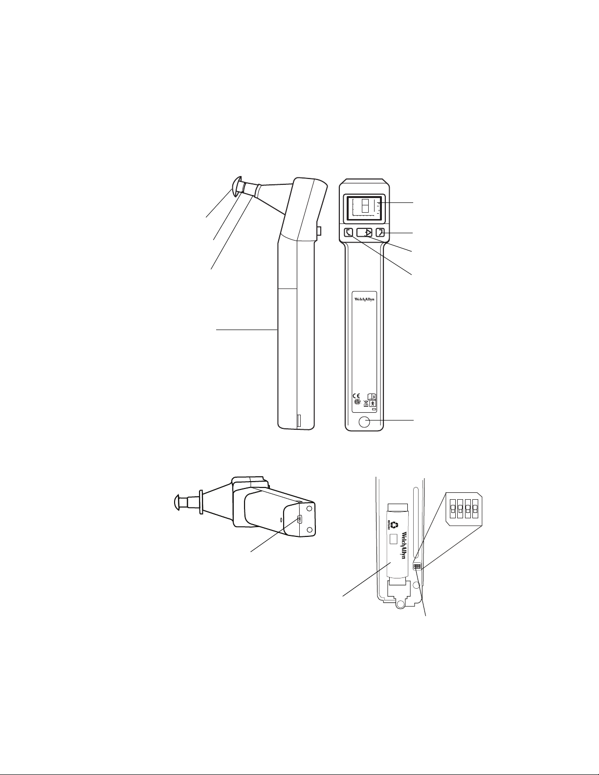
Liquid Crystal
Display (LCD)
Left memory button
Test button
Right memory button
Infrared data
transfer window
Tip
Probe
Tip
ejector
Battery
cover
Micro-USB port
NOTE: Reserved for future use
Lithium-ion
battery
Side view Front view
Bottom view
Interior view
Handle
switches
Controls, indicators, and connectors
Handle components
Page 10
6 Introduction and technical overview Welch Allyn MicroTymp3 Handle and MicroTymp Printer/Charger
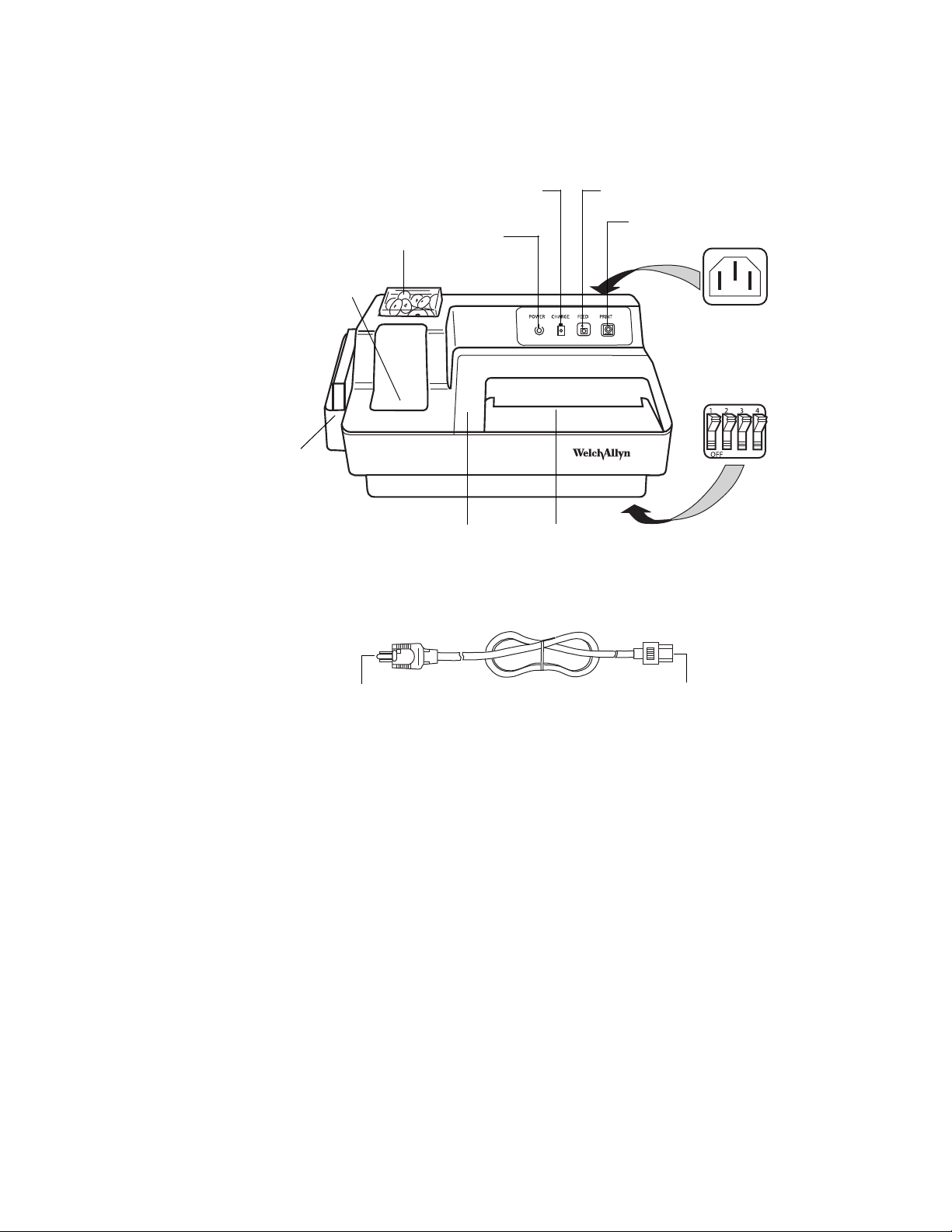
Power Cord
Tip box
POWER
indicator
CHARGE
indicator
FEED button
PRINT button
Paper
slot
Paper access
cover
Charging well for
MicroTymp 2 or 3
Card holder
with 1000-Hz
screening
results cards
IEC power cord
receptacle
Printer/Charger
switches
To IEC power
cord receptacle
To power
receptacle
Printer/Charger components
Page 11
Service manual Introduction and technical overview 7
TEST
GR
A
L
C
GR
-20ºC
+49ºC
95%95%
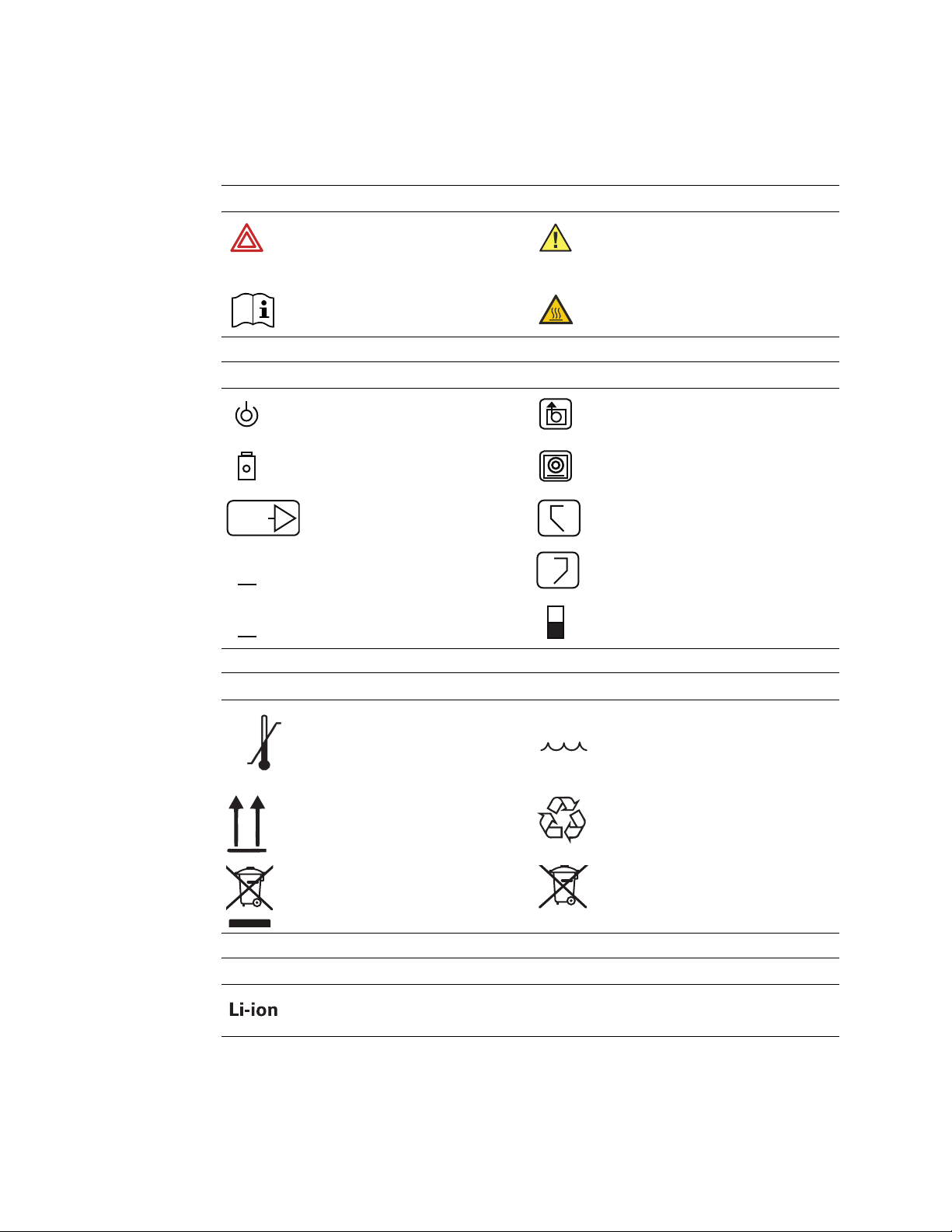
Symbols
Documentation symbols
Warning
(Warnings indicate conditions or practices
that could lead to illness, injury, or death.)
Consult instructions for use Hot surface
Operation symbols
POWER indicator FEED button
CHARGE indicator PRINT button
Caution
(Cautions indicate conditions or practices
that could damage the equipment or other
property)
TEST button RIGHT memory button
Gradient width adult LEFT memory button
Gradient width child Switch options ON/OFF symbol
Shipping, storing, and environment symbols
Temperature limits Relative humidity limit
This end up Recycle
Recycle the product separate from other
disposables. See www.welchallyn.com/
weee for collection point and additional
information.
R
Separate batteries from other disposables
for recycling.
Power and connectivity symbols
Lithium-ion
Page 12
8 Introduction and technical overview Welch Allyn MicroTymp3 Handle and MicroTymp Printer/Charger
0297
REF
SN
Certification symbols
Meets essential requirements of European
Medical Device Directive 93/42/EEC
74227
Class I equipment, Type BF
(Handle)
Class I equipment, Type B
(Printer/Charger)
Miscellaneous symbols
Reorder number Manufacturer
Complies with applicable U.S. and
Canadian medical safety standards
European regulatory manager
Serial number
Page 13

Service manual Introduction and technical overview 9
General warnings
WARNING Explosion risk. Do not use Handle or Printer/Charger near flammable
anesthetics.
WARNING Electric shock hazard. Do not attempt to disassemble the Printer/
Charger. Refer all servicing to Welch Allyn or a Welch Allyn authorized service
representative.
WARNING Electric shock hazard. Use the USB connector only to connect to
devices complying with IEC 60601-1 or other IEC standards as appropriate to the
device. The user is responsible for verifying that the system complies with the
requirements of the system standard IEC 60601-1-1 if additional devices are
connected to the Handle.
WARNING Improper handling or disposal of the battery can lead to heat
generation, smoke, bursting, or fire.
WARNING Do not disassemble, modify, or solder the battery.
WARNING
battery terminals.
WARNING To avoid short circuits, keep the battery terminals away from metal
objects.
WARNING Do not dispose of the battery in fire.
WARNING Do not expose the battery to temperatures above 80°C (176°F).
WARNING Use only the specified charger to charge the battery.
General cautions
Caution Charge only Handle #23640, Handle #23650, or AudioScope 3
(#23300) in the Printer/Charger.
Do not directly connect (short circuit) the positive (+) and negative (–)
Caution If the device has not been stored within the operating temperature
range, allow 24 hours minimum for it to return to operating temperature range
(15-35°C or 59-95°F) before using.
Page 14

10 Introduction and technical overview Welch Allyn MicroTymp3 Handle and MicroTymp Printer/Charger
Caution Do not store either the Handle or Printer/Charger at temperatures
below -20°C (-4°F) or above +49°C (120°F). Continual exposure to extremely low
or high temperatures can permanently damage components.
Caution The battery must be removed if the Handle is to be stored or placed
anywhere other than in the powered Printer/Charger for more than one month.
Failure to do this can result in damage to the Handle.
Caution This instrument contains components which are static sensitive.
Before touching any internal Handle component, be sure that you have
discharged any static electricity by touching a grounded metal object.
Caution To prevent equipment damage, charge the Handle only with the
Printer/Charger (#7117x).
General notes
The Printer/Charger (#7117x) will charge and print data from the MicroTymp2 or
MicroTymp3 Handle. However, the original Printer/Charger (#7113x) will neither charge nor
print data from the MicroTymp3 Handle.
Please complete and return the warranty registration. It validates the warranty and allows
Welch Allyn to communicate calibration notices and software changes.
Page 15

11
Pressure box (T-5657 or equivalent) Test cavity set (T20015974)
2
Too ls
Testing and verification
• Pressure applicator source with range of -400 to +300 daPa with 1 daPa
resolution
• Variable voltage (0-10 VDC) output power supply with at least 500 mA capacity
• Test cavity set, part number T20015974. See picture below for sizes.
• Handle
• Printer/Charger
• Digital voltmeter 3 ½ digit
• Hemostat or crimping needle nose pliers
• Set screw key, size 0.035
• Nut driver size 5/32 inch or 4 mm, thin wall preferred
• Other nut driver sizes needed: 3/16 inch and 1/4 inch
• Small and medium size Philips screwdrivers
• ROHS (lead free) soldering iron and lead free solder
•Tweezers
• Stop watch for leak test
• Service computer (Windows XP
25, 2009. This program will give control of the Handle during the bench test. For
Sample Client to work On-Host Version 1.0.0 or equivalent must be installed prior
to using the WACP Sample Application.
• USB cable (thin connector) for connection to service computer
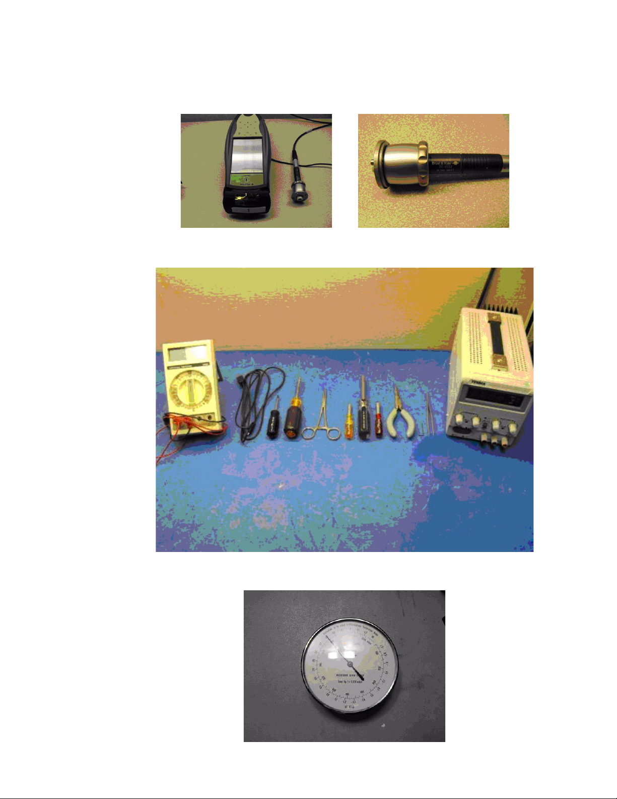
• B&K sound level meter model 2250, with ½-inch microphone model 4192 and
2 cc coupler model 4946
• Barometric Pressure transducer, model 276 or equivalent (must measure
pressure in mmHg)
1
1
®
, or higher) with 'Sample Client,’ version June
1. These pieces are ATE. They are needed when the calibration is updated but not for the bench test.
Page 16
12 Testing and verification Welch Allyn MicroTymp3 Handle and MicroTymp Printer/Charger
B&K sound level meter model 2250 1/2-inch microphone model 4192 and
2 cc coupler model 4946
Off-the-shelf tools
Barometer
Page 17
Service manual Testing and verification 13
Note
Note
Sample client location
Bench test and calibration check - Handle
Purpose of test
To test for and detect problems in the following portions of the Handle:
1. Leak and vent rate
2. Noise (226 and 1000 Hz) and sweep rate test
3. Compliance check
For the purpose of detecting and repairing problems before the unit is run on the ATE.
This will alleviate failures on the final ATE test. Therefore, these tests should be
performed before final testing on the ATE.
Refer to the “Troubleshooting guide” starting on page 29 for solutions to the problems
encountered during the bench and ATE tests.
Preparation for test
Use only the functions of sample client as set forth is this manual.
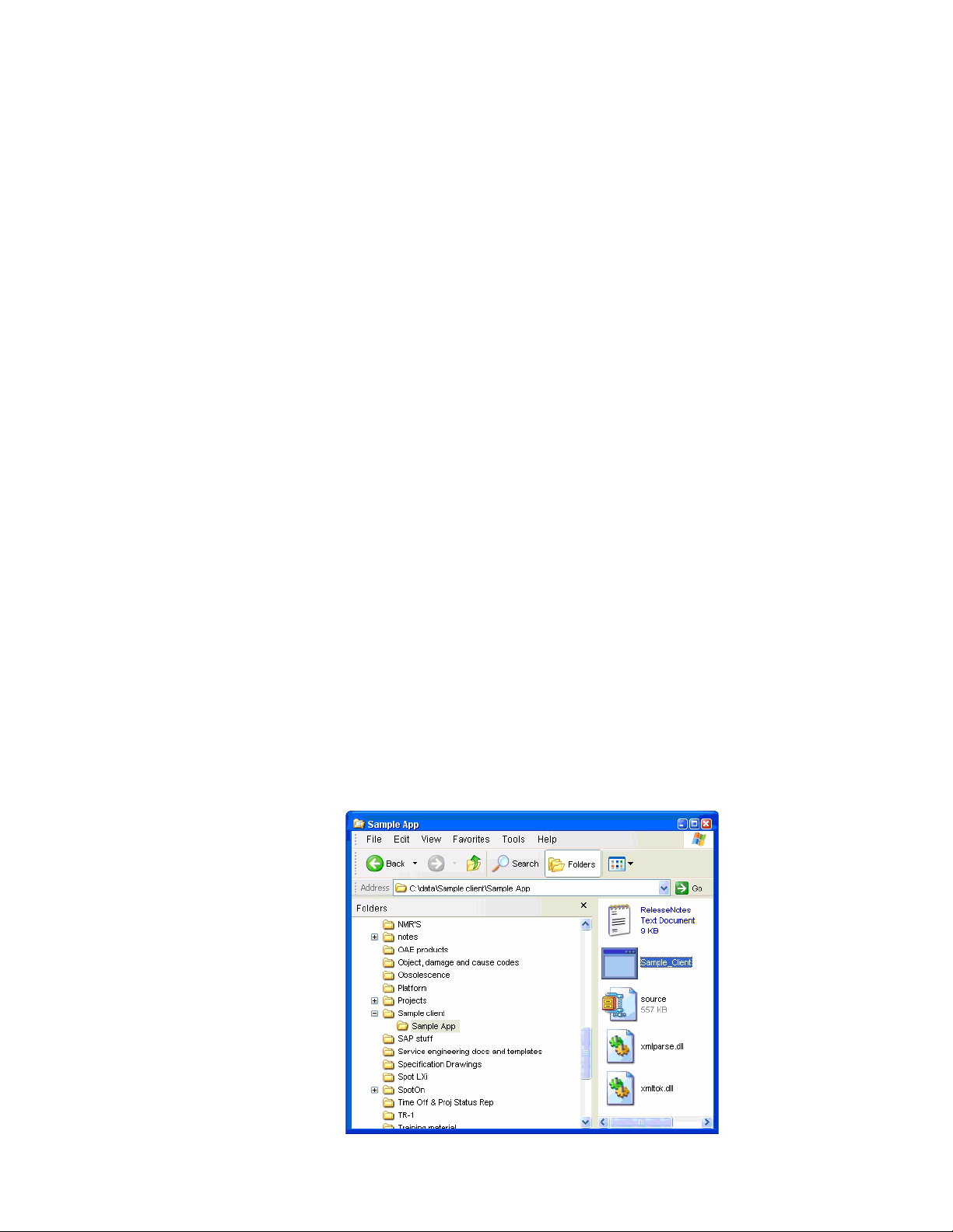
1. Open the sample client program on the service computer by navigating to the
'Sample Client' folder. Open it and click on the 'Sample App' folder. Double click on
the 'Sample Client' file. Program will open. See opening screen picture.
2. Connect USB cable from Handle to service computer.
Any time a new battery is installed it is necessary to connect the MicroTymp
handle to the USB cable or insert it into the printer/charger for five seconds before
powering up the handle. (This enables the battery protection circuit).
Page 18
14 Testing and verification Welch Allyn MicroTymp3 Handle and MicroTymp Printer/Charger
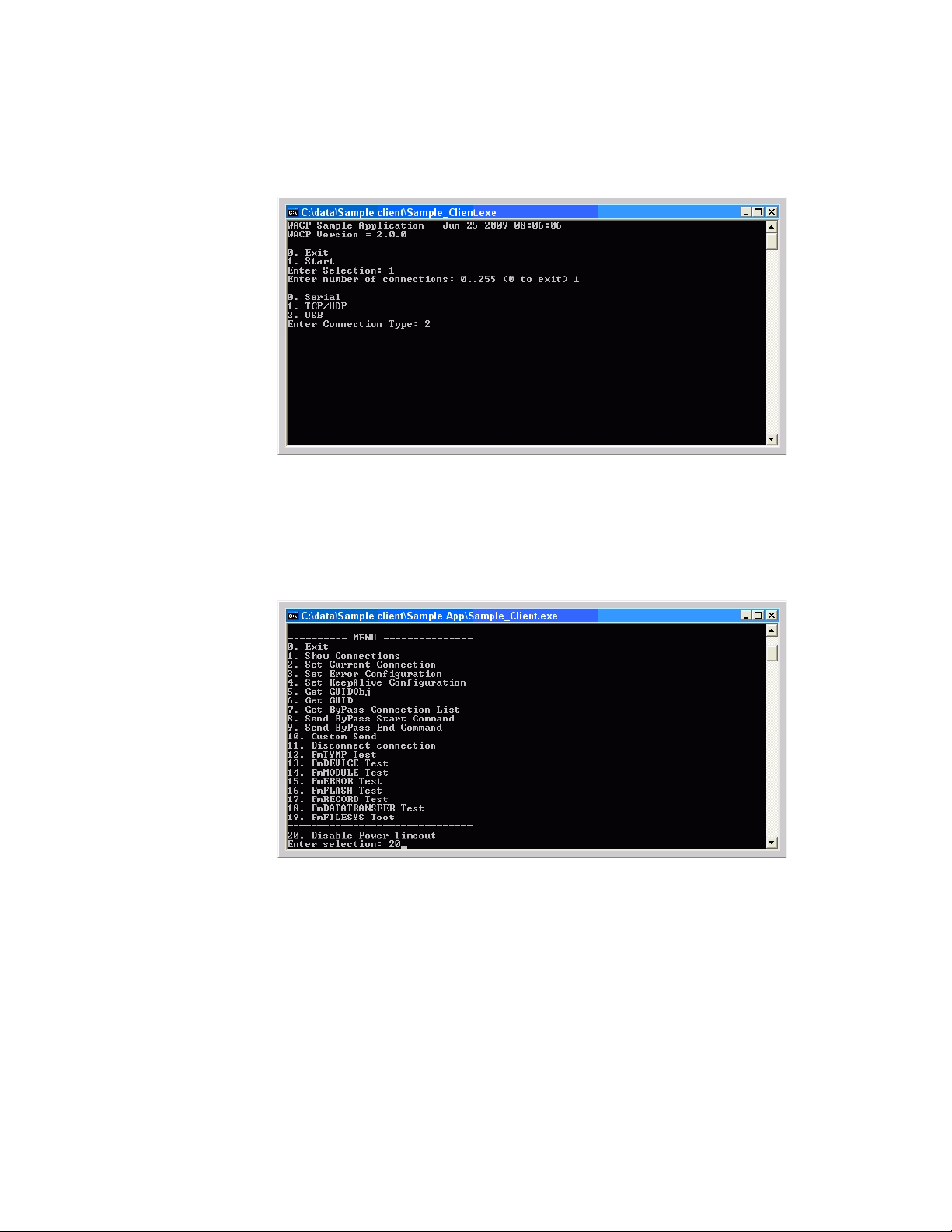
Opening screen
Sample client menu
3. Select the choices as shown in the picture below: 1 for start, 1 for number of
connections, and 2 for USB.
4. An extensive menu should display on the service computer screen. Making sure that
the Handle is powered on, select the number of the 'Disable Power Timeout,'
selection number 20. This will enable the Handle to stay powered up throughout the
test.
Bench test procedures
Test 1 - Leak and vent tests
1. With the main menu still showing on the service computer screen, select number 12,
FmTYMP Test. The FmTYMP Test screen will show. Select number 3, Send
command. Select number 14, Set Valve. Select number 1 to close valve. An audible
click will be heard indicating the valve has been latched closed. Unit can now be
tested for leaks.
2. Connect pressure box to the probe tip of the Handle. Throw select switch on pressure
box to positive position and pressure/vent switch to pressure position.
Page 19

Service manual Testing and verification 15
Note
1000 Hz Typmanogram
Volume
of
tested
cavity
3. Adjust box to 300 daPa, let it sit for about ten seconds, and then observe the leak
rate. It must be less than 10 daPa in five seconds.
4. Vent the unit by throwing the pressure/vent switch on the box to vent position (V).
5. Put select switch in negative position and pressure/vent switch to pressure position.
6. Adjust pressure to -400 (meter will read +400), wait ten seconds, and then observe
leak rate. It must be less than 10 daPa in five seconds.
7. Readjust pressure to -400 daPa.
8. Open valve on Handle by selecting number 2, Open Valve, on the service computer.
Pressure should drop to zero in two seconds or less.
9. To re-enable the timeout circuit, simultaneously press/release all three buttons on
Handle. Unit will power down. Power up unit and confirm that unit powers down in
about fifteen seconds.
Test 2 - Noise and sweep rate tests
1. Set the unit to 226 Hz.
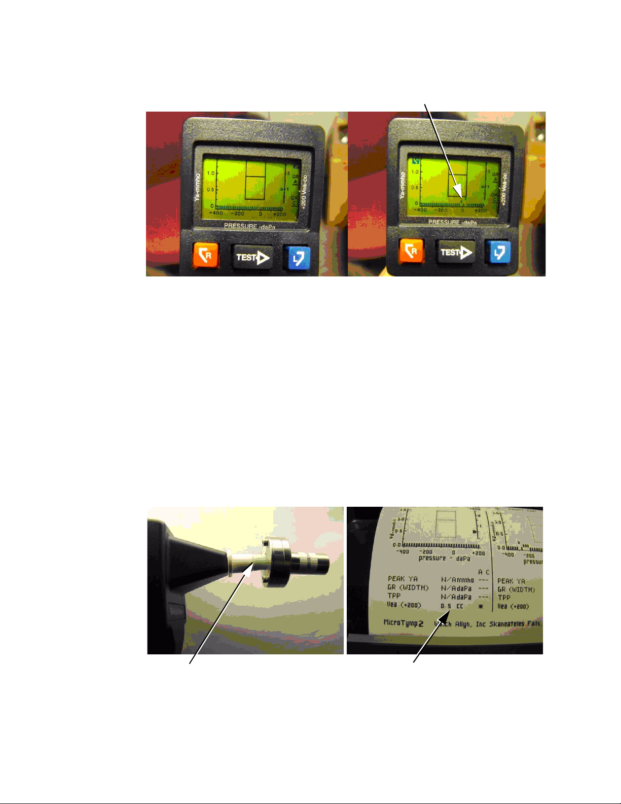
2. Put a 0.2 cc cavity on the probe tip. Hold unit upright and take a reading.
3. There should be a straight line across the bottom. Ideally, there should be no pixels
above the base line. If there are pixels one row above that is acceptable. Any pixels
two rows or more above the base line constitutes a failure. See pictures at the end of
this section.
4. Take four tympanograms and make sure all readings are a pass.
5. In addition, note the sweep across the bottom of the screen during a tympanogram. It
should move at an even speed. Make sure there is no notable slowdown or sudden
start/stops.
6. Repeat steps 2 through 5 for the 2.0 cc cavity.
7. Set the unit to 1000 Hz.
The cavity test for 1000 Hz will show the correct volume but not a straight line
across the bottom of the LCD. The line may be slightly elevated but no higher
than 0.4 mmho. It is important that the correct volume is displayed. A REFER
message will also appear on the LCD, and it does not indicate a problem.
8. Perform cavity tests for 1000 Hz with the 0.2 and 2.0 cc cavities.
Page 20
16 Testing and verification Welch Allyn MicroTymp3 Handle and MicroTymp Printer/Charger
Good tympanogram (226 Hz) Unacceptable tympanogram (226 Hz)
Note
Properly applied test cavity Printout of test tympanogram
No gap shown
Volume reading
Test 3 - Compliance check for 226 Hz function only
1. Place a 0.5 cc cavity onto the probe tip. Make sure cavity fits properly. The rubber tip
from the cavity should not be pulling away from the white tip ejector. See picture
below.
2. Press the 'TEST' button on the Handle. The unit should take a reading as a flat line
across the bottom of the screen. Press the 'L' button to store the reading into the left
memory. Observe the 'LEFT STORE' message.
3. Insert Handle into Printer/Charger and print out results. The Vea reading should be
0.5 cc +/- 0.1 cc.
4. Repeat steps 1 through 3 with a 1.5 and a 2.4 cc cavity, but press the 'R' button to
store the readings into the right memory. The Vea reading should be the cavity size
+/- 0.1 cc.
Unit is now ready for final test on the ATE.
All units must be tested on the ATE before shipment to the customer.
Page 21

Service manual Testing and verification 17
Final Tester Setup
Before a unit can be tested on the final tester, the B&K meter must be calibrated at the
beginning of each shift. Please follow the instructions below to calibrate the tester.
1. Turn on the computer of the ATE tester.
2. Select the ATE Operator button at the Windows log-in screen.
3. Double-click the Shortcut to Platform icon.
4. After the MicroTymp 3 ATE test screen displays, select Setup.
5. Remove the 2cc coupler from the ATE Microphone. Rotate the lock ring on the 2cc
coupler counterclockwise to unlock the mechanism.
6. Place the ATE Microphone onto the calibration sound box.
Page 22

18 Testing and verification Welch Allyn MicroTymp3 Handle and MicroTymp Printer/Charger
Note
7. Press the On/Off button located on the side of the calibration sound box to turn
it on.
8. Select the Calibrate SLM button on the ATE Screen.
9. After the ATE screen displays "Calibration is Complete", rotate the lock ring on the 2cc
coupler counterclockwise to unlock the mechanism. Re-insert the B&K microphone
into the coupler and ensure that the microphone is fully seated before rotating the
lock ring clockwise to lock as shown below.
Check that the internal threads between the two coupler pieces are tight before
using the locking mechanism.
Page 23

Service manual Testing and verification 19
Lock
Ring on
2cc
coupler
Testing a Unit
Caution When removing the coupler (or any test cavities) from the Unit Under
Test (UUT), use the Tip Ejector to minimize the stress on the 2cc coupler and
tips.
Before testing each new unit, make sure the microphone is pushed all the way into
the 2 cc coupler and that the the coupler is locked.
Once the ATE instructs you to put on the 0.2 cc cavity, you must use the tip ejector on
the unit to disengage the microphone with the 2 cc coupler from the unit. DO NOT
pull the microphone off of the unit.
1. Prepare the unit for the ATE tester. Double click on test, then double click on test
again.
Page 24

20 Testing and verification Welch Allyn MicroTymp3 Handle and MicroTymp Printer/Charger
Note
2. Attach the unit to the battery simulator by the sliding battery simulator into the battery
holder on the unit’s power board. (The cover may be secured with a battery cover
screw.)
3. Attach USB cable to the bottom of the unit.
The USB symbol on the cable faces up toward the top (or label side) of the unit.
4. Place Unit Under Test (UUT) into the ATE Nest. Use the touch screen of the ATE (or
the mouse) to begin the test. Follow the ATE Tester direction on the screen.
Page 25

Service manual Testing and verification 21
QP6
FINAL TESTER
EquipmentMethod
Acceptance Criteria
Record
Include the IPA# if the unit fails any stage of the final test. Sign
and date the signature block for QP5 on the MT3 Handle DHR.
20015994 workstation
- Automated verification and calibration of units
- Unit passes all final tests
- Mark the appropriate PASS or FAIL checkbox for final test.
After the successful completion of the final test
1. Remove the unit from the printer/charger.
2. Remove the battery from the unit.
3. Set the unit aside.
4. Write the unit serial number, the date, and your initials on the printout.
5. Staple the printout to the DHR.
Page 26

22 Testing and verification Welch Allyn MicroTymp3 Handle and MicroTymp Printer/Charger
Testing Performed by the ATE
For reference only - actual numbers may change
Each Handle that is tested by the ATE receives the following tests:
1. Preliminary Current Check: 20 to 400 ma.
2. Test Initialization.
3. Firmware Check and Upgrade: new units only.
4. Low Battery Test: 2.9 volt DC threshold.
5. Electrical Current Test: 20 and 140 ma.
6. Configuration Switches Check.
7. EEPROM Read/Write: initialize new, read and save calibration (cal) record on existing
units.
8. Set Unit Information: name and model number, serial number, MCU and PS board
barcode information, device firmware version, date of first cal, date of last cal, ATE
software version for last cal and serial number of ATE used for last cal.
9. Real Time Clock Calendar Set and Test: write time and date and verify it can be set;
verify accuracy within ten seconds after being powered down for two minutes.
10. Button Test: check left, right, and test buttons.
11. LCD Test: all on, all off, checkerboard, inverse checkerboard.
12. Leak Rate Test: 10 daPa for five seconds at 200 and at -400 daPa.
13. Pressure Calibration: calibrate at 200, 0 and -400 daPa.
14. 226 Hz Sound Calibration and Verification: output set to 85.0 +/- 0.1 dB.
15. 226 Hz maximum Sound Pressure Level: max SPL less than 95 dB.
16. 226 Hz Microphone Calibration: microphone set to proper output with 85.0 dB output
from speaker.
17. 226 Hz Frequency Verification: frequency within +/- 4 Hz.
18. 226 Hz Total Harmonic Distortion (THD): THD needs to be less than 3% at 85.0 dB.
19. 1000 Hz Sound Calibration and Verification: output set to 83.0 +/- 0.1 dB.
20. 1000 Hz maximum Sound Pressure Level: maximum SPL less than 95 dB.
21. 1000 Hz Microphone Calibration: microphone set to proper output with 83.0 dB
output from speaker.
22. 1000 Hz Frequency Verification: frequency within +/- 20 Hz.
23. 1000 Hz Total Harmonic Distortion (THD): THD needs to be less than 3% at 83.0 dB.
24. Admittance LUT Generation and Verification: calibration test cavity admittance
adjusted for current barometric pressure to calibrate unit at sea level.
Page 27

Service manual Testing and verification 23
Note
Power switch
25. Admittance Accuracy: checked with 0.5, 1.5, and 2.4 cc cavities. Accuracy needs to be
within +/- 0.1 mmho for 226 Hz and +/- 0.4 mmho for 1000 Hz or +/- 5%, whichever is
greater.
26. Motor Speed Look up Table (LUT): created and checked with 0.2, 0.5, 1.0, 1.5, 2.0, and
2.5 cc cavities. Sweep time shall be 1500 +/- 25 ms.
27. EEPROM Verification: Checksum calculated by unit under test.
28. 226 Hz Admittance and Volume Accuracy Test (Noise): checked with 0.2, 1.0, 2.0, and
2.4 cc cavities, four times with each cavity. Vea accurate to +/- 0.1 cc. Maximum
allowable noise is 0.1 mmho on at least three of four times with each cavity.
29. 1000 Hz Admittance and Volume Accuracy Test (Noise): checked with 0.2, 1.0, 2.0,
and 2.4 cc cavities, four times with each cavity. Vea accurate to +/- 0.1 cc. Maximum
allowable noise is 0.4 mmho on at least three of four times with each cavity.
30. Printer/Charger Connectivity Test: connectivity shall be confirmed for charging the
battery and sending and printing data downloaded from the Handle to the printer.
31. All UUT result files shall be stored in the secure repository located on the ATE hard drive.
32. The ATE shall print all Test Results of the UUT.
33.
The ATE shall print the UUT Label Printout if there were no failed test results for the UUT
Failure of the Handle during any part of the ATE test necessitates running that
entire test upon repair of the problem.
Bench test for the Printer/Charger
Refer to the Troubleshooting guide in Chapter 3 for solutions to the problems
encountered during the bench test. The Printer/Charger requires no ATE final test.
Proper powering up of unit
1. Power printer up by plugging into suitable wall outlet. Make sure all switches on
bottom of unit are in the 'OFF' position.
.
2. Make sure there is data in both the left and right memory on the Handle.
3. With paper loaded into unit, the green power light should come on without blinking,
and there should be a single beep. The green charge light should not be lit.
4. Unplug unit and remove paper roll. Note paper roll installation.
Page 28

24 Testing and verification Welch Allyn MicroTymp3 Handle and MicroTymp Printer/Charger
Pull lever
Forward position
of lever
Pull lever
Backward position
of lever
5. Power up unit. Power light should blink in a pattern of one on, one off.
6. Install paper roll by feeding under gray rubber printer roll and pressing the feed button.
Push paper forward until it comes out at the top of the roller. Feed about three more
inches from this point.
7. Pull lever on right side of print head toward the front of printer. Power light should
blink twice in rapid succession.
8. Push lever all the way back. Power light should stop blinking and stay on. This is
normal operating mode for the Printer/Charger.
Proper operation of print head
1. Simultaneously depress/release the print and feed buttons to generate the following
printout:
Page 29

Service manual Testing and verification 25
Graph Tympanometric data Adult/child data
2. Make sure there are no gaps in the grid printout and that all lines of date are full with
no lines missing through the lettering.
3. Insert Handle into Printer/Charger well with the LCD screen facing forward. The
charge light should light.
4. Press the ‘PRINT’ button. Notice the printout. It should contain adult/child data,
tympanometric data, and the graph.
Page 30

26 Testing and verification Welch Allyn MicroTymp3 Handle and MicroTymp Printer/Charger
Printout with Switch 2 in ON position
Printout with Switch 3 in ON position
5. On the switch pack on under side of printer, put switch 2 to ON position. Press the
print button. Notice the printout. There is no adult/child data.
6. Put switch 3 to ON position. Press the ‘PRINT’ button. Notice the printout. There is
neither adult/child nor tympanometric data.
7. Put switches 2 and 3 back to OFF position and switch 1 to ON position. Remove
Handle from well for about three seconds, then re-insert. Handle will download data
then automatically print out a full set of data.
Agency tests
Dielectric strength test
Perform this test between primary wiring (both sides of supply terminals connected
together) and accessible dead metal parts (non-current carrying conductive parts) 1000
VAC (1200 VAC for one second).
Page 31

Service manual Testing and verification 27
Tes t p r obe
Unit under test
1 k resistor
15 uf capacitor 10.2 ohm resistor
Breakdown will normally be indicated by tripping of a suitable overload protector in the
test equipment, but an abrupt decrease or retarded advance of the voltmeter reading
could also be indicative of insulation failure. REF: UL544 par. 31.3.
A breakdown is also considered to have occurred if after the test the equipment does
not comply with risk current test even though there is no arcing, tracking, or other
evidence of a breakdown. REF: CSA 22.2 #125, 6.7.3 Note 5.
Grounding continuity test
This test checks the integrity of the earth ground by applying current through the earth
ground of the line cord and unit. The voltage is measured across the earth ground prong
of the outlet and any accessible metal part of the appliance, and this voltage shall not
exceed 2.0 volts. See calculation.
E = IR > E = 10 x 0.2 > E = 2 volts maximum
Statement from grounding continuity test standard: The resistance between the
grounding pin of the attachment plug and any accessible metal part of the appliance shall
not exceed 0.2 ohm. Test will be conducted using a 10 amp current source with a no-load
voltage not exceeding 6 volts DC for five seconds.
REF: UL544, PAR. 33.1A
IEC601-1, Clause 18 Par. F
Leakage current test
This test checks the current measured from any exposed metal parts to ground with an
input voltage of 120 volts AC at 60 Hz or 240 volts AC at 50 Hz and the ground wires
securely connected. The leakage current in these circumstances shall be less than 50
microamps. See circuit below. The voltage measured across the 1k resistor during this
test shall be 47.5 millivolts or less.
Page 32

28 Testing and verification Welch Allyn MicroTymp3 Handle and MicroTymp Printer/Charger
Page 33

29
3
Handle
Troubleshooting guide
Problem Cause Corrective Action
No Tone Check solder connections on speaker/
microphone flex
Make sure speaker/microphone is
properly seated in boot and on SS tube
Check for a clogged SS tube in the
front housing
Defective speaker/microphone
Defective MCU PCB
Unit has tone but there is an open
message w/cavity on probe tip
Tympanogram fails noise test (second
pixel from right is high or missing)
LCD dim or not on Check VCC power; should be at least
Keypad button (s) not working Make sure flex is properly seated
Handle does not power up Low battery voltage
Handle does not download data to
Printer/Charger
Handle battery not charging Battery defective
Tympanogram not finishing, or
noticeably slowing down toward
-400 daPa
Shows leak message when attempting
tympanogram
Tympanogram noisy where the second
pixel is OK
Shows block message w/cavity on
probe tip
Shows block message at all times Debris in probe tip
Fails sound calibration Clogged probe tip tube (s)
Fails motor speed test on ATE Set screw too loose or too tight
Defective microphone
Clogged microphone tube
Defective MCU PCB
Microphone defective Replace microphone
4.8 volts
Defective LCD board
Keypad board defective
Flex cable loose
Defective PS board
Handle not powering up
Defective MCU PCB
Poor connection at charge contacts
PS board defective
Leak in unit
Pump pulley set screw too tight
Unit has a fast leak
Defective pump assembly
Defective or misaligned component Repair noise problem according to the
Unit out of calibration
Defective MCU PCB
Defective MCU PCB
Defective speaker
Defective MCU board
Defective drive belt
Leak in unit
Reflow solder connection
Reseat speaker/microphone as needed
Clean tube as necessary
Replace defective part
Replace MCU PCB
Replace microphone
Clean tube
Replace MCU PCB
Replace PS board
Replace LCD board
Reseat flex
Replace keypad board
Charge/replace battery
Reseat flex cable
Replace PS board
Solve power problem
Replace MCU PCB
Replace battery
Repair poor connection
Replace PS board
Repair leak according to the leak
repair procedure
Readjust set screw
Repair leak according to the leak
repair procedure
Replace pump assembly
noise repair procedure
Calibrate by running unit through ATE
test
Replace MCU PCB
Clean debris from probe tip
Replace MCU PCB
Clean probe tip tube(s)
Replace speaker
Replace MCU PCB
Readjust pulley set screw
Replace drive belt
Repair leak according to leak repair
procedure
Page 34

30 Troubleshooting guide Welch Allyn MicroTymp3 Handle and MicroTymp Printer/Charger
Problem Cause Corrective Action
Unit fails current drain test on ATE Pump not finding home position
Defective PS or MCU board
LCD frozen, unresponsive Microcomputer MCU board has locked
up
MCU board has failed
Unit reads 'NEEDS SVC' Hard failure in unit Retrieve error code from sample client
Unit reads 'SYS CHK' Illegal condition in unit Power down by pressing/releasing all
Unit reads 'CAL DUE' One year has passed since last
calibration. Unit due for calibration.
Unit prints “No data. Reinsert Handle’ Switch 2 in wrong position on switch
pack in Handle
Replace pump
Replace appropriate PC board
Press/release all three buttons
simultaneously, then power on
Replace MCU board
program. See instructions in section 5.
Repair, perform bench test and run
through ATE.
three buttons simultaneously. Power
back up. If message goes away,
perform bench test and run through
ATE. If message persists see
instructions in section 5.
Perform bench test then calibrate unit.
Put Switch 2 in correct position
Printer/Charger
Problem Cause Corrective Action
Does not power up; fuse blown Defective print head
Defective main PCB
Does not power up; fuses OK Defective main PCB Replace main PCB
Does not feed paper Cable P302 not properly seated
Defective printout Paper defective
Does not receive data Cable P301 not properly seated
Power light does not light Cold solder joint at P302
Charge LED not lighting when Handle
is inserted into charging well
Charge LED on without Handle in well Defective main PCB Replace main PCB
Power LED blinking No paper in printer
Power LED blinking twice in rapid
succession
Unit fails Dielectric strength test Defective RFI filter
Unit fails ground continuity test Broken or frayed ground connection
Unit fails leakage current test Defective RFI filter
Print head lever out of position
Defective print head
Print head defective
Cold solder joint on contact housing
assembly or P301
Defective contact housing assembly
LED defective
Main PCB defective
Cold solder joint at P301, P302 or
contact housing assembly
LED defective
Defective print head
Print head lever in wrong position Put print head lever in correct position
Defective transformer on main PCB
Defective power cord
Short between circuitry on main PC
board and ground part(s)
Replace print head
Replace main PCB
Reseat cable P302
Put lever in correct position
Replace print head
Replace paper
Replace print head
Reseat cable P301
Reflow solder connection
Replace contact housing assembly
Reflow solder connection
Replace printer keyboard assembly,
p/n 711704-501
Replace main PCB
Reflow solder connection
Replace printer keyboard assembly,
p/n 711704-501
Install paper
Replace print head
Replace RFI filter
Replace main PCB
Repair broken connection
Replace power cord
Replace RFI filter
Remove short
Page 35

Service manual Troubleshooting guide 31
Noise troubleshooting procedure
The purpose to these instructions is to give a general procedure in fixing a noisy Handle
when the cause is not the microphone (second pixel on tympanogram is acceptable).
1. Verify the problem by testing the unit manually with 0.2 cc, 1.0 cc, 2.0 cc, and 2.4 cc
cavities.
2. If the unit is noisy when testing manually, proceed as follows:
a. Remove battery cover.
b. Examine all tubing for kinks, bends, or anything that might restrict air flow.
c. Make sure all tubing is connected to the right place and routed per the drawings.
d. Test whole system for leaks. Leaks will cause noise in the system. Refer to
“Test 1 - Leak and vent tests” on page 14.
3. Remove screws from front housing.
4. Break fiber strips from front housing.
5. Slowly remove the front housing from the back housing. While disassembling,
complete the following actions:
a. Check to see if the microphone, speaker, or pressure transducer parts are
touching each other or the front housing. If they are, this will cause noise in the
unit.
b. Check to see if the silicone tubing from the front housing to the ballast is pinched.
c. See if the bottom flex is routed per drawing around the LCD boss.
d. See if silicone tubing is routed correctly between the pump and frame.
6. Fully open and examine the front housing:
a. Inspect the arrangement of the microphone, speaker, and pressure transducer.
b. Check the positioning of the pump in the back housing.
c. Check to see if all padding is on the pump, top cap, and back housing, and that it
is positioned correctly.
7. Correct any problems identified and reassemble the Handle.
8. Check the Handle for noise. If the Handle is still noisy, disassemble the unit and
replace motor. Reassemble the unit and recalibrate. Perform a noise check.
9. If the unit is still noisy, replace the pump assembly and reassemble. Recalibrate the
unit and check for noise.
Page 36

32 Troubleshooting guide Welch Allyn MicroTymp3 Handle and MicroTymp Printer/Charger
Pressure
transducer joint
Top c a p j oint
Ballast
connection
Valve
connection
'T' joint
Leak troubleshooting procedure
The purpose of this procedure is to isolate a leak in the pneumatic assembly of the Handle
so that an accurate diagnosis and repair can be performed.
For this procedure a Hemostat tool is required.
1. Hook up the pressure applicator source to the unit.
2. Using the sample client program, close the valve and apply about 200 daPa to the
unit.
3. Observe the leak rate. Apply the hemostat to the silicone hose between the pressure
transducer joint and the 'T' joint. See picture below.
4. Observe leak rate again. If leak rate remains constant or increases the leak is in the
pressure transducer area. Repair leak and retest. If leak rate stops, remove hemostat
and proceed to step 5.
5. Apply hemostat to hose between 'T' joint and top cap joint. If leak rate remains
constant or increases the leak is in the 'T' joint, ballast or valve areas. Proceed to step
6. If leak rate stops, leak is in the top cap joint or pump assembly. Repair leak and
retest.
6. Move hemostat to hose between valve and ballast. If leak rate remains constant or
increases the leak is either the 'T' joint or ballast area. Repair leak and retest.
7. If the leak rate stops, the leak is in the valve. Repair leak or replace power board and
retest.
Page 37

Service manual Troubleshooting guide 33
Error and service code tables with troubleshooting procedure
This procedure shows the error codes, their probable causes and solutions and the
method of logging of such codes.
Error codes
Code Description Probable cause
EF CHECKSUM_ERROR MCU problem
EE THREADX_ERROR MCU problem
ED AUDIO_ERROR MCU problem
EC SLAVE_COMM_ERROR MCU problem
EB HOME_PUMP_ERROR Pump or flex problem, PS problem
EA AUTO_ZERO_ERROR Pressure transducer or pump or sensor flex problem
E9 SLAVE_STATUS_REGISTER MCU problem
Error codes can be used to help determine the root cause of a problem condition. The
error log is listed in the following format “YYYY-MM-DD HH:MM:SS Category Code.” See
explanation of Category Code on page 34.
Retrieving and clearing error codes
To retrieve the errors from a unit, hook up the Handle to a service computer via USB
cable. Navigate to sample client program. Disable power timeout per “Preparation for
test” on page 13.
Type in the following sequence:
On main menu, enter 12, FmTYMP Test; enter 13, Data Transfer (LUTs, Logs,
EEPROM); enter 2, Logs; enter 1, Error. The following screen will appear.
Notice the second line from the bottom, MicroTympErrorLog.txt:Done 100%.
When this error log selection is executed the program will create a file called
‘MicroTympErrorLog’. This is in the ‘sample app’ folder. See screen shot on next page.
Page 38

34 Troubleshooting guide Welch Allyn MicroTymp3 Handle and MicroTymp Printer/Charger
If no errors are to be logged, the last two numbers on the error log in this file will be
00 00. This is called a ‘clean’ error log. See example below for explanation.
The date is retrieved from the real time clock on the Handle. The format of the date is
shown as: “2009-07-15 14:12:07”
Here is an example of a clean error log: "2009-01-01 00:02:07 00 00" where 00 indicates
no error category and 00 indicates no cause, or defective software function.
Below is an example of the error listings found in this file.
2009-09-04 17:08:37 EC CA See category code explanation below
2009-09-04 17:09:11 EC CA
2009-09-04 17:49:10 EC CA
2009-09-04 17:51:42 EC D1
2009-09-04 17:51:48 EC CA
2009-09-04 17:52:20 EC CA
2009-09-04 17:55:52 EC CA
2009-09-04 17:56:26 EC CA
2009-09-04 17:59:46 EC CA
2009-09-04 18:01:19 EC CA
2009-09-04 18:08:10 EC CA
Note that if data from another Handle is extracted, the program will overwrite the first file,
erasing that data from the first unit. To avoid this, rename or relocate the first file when
finished with the first unit.
To clear the error log, navigate to the main menu. Enter 12, FmTYMP tests; enter 3,
Send Command; enter 3, CLEAR_ERROR_LOG. Errors will be cleared.
Service codes
Service codes are those messages that display on the LCD of the Handle. They indicate
the condition of the unit. The available service codes are listed in the ‘Display’ column in
the table on the following page. With the exception of the codes ‘NEEDS SVC’ and
‘NEEDS CAL,’ all other codes can be reset by powering down, then powering up. There is
a table on the next page showing the service codes along with pertinent information that
the Handle will display.
1
1. Concerning the last two pieces of data, the first one listed is the error category code (EC) which is listed in step 1 on the previous page
and the particular data string (CA) which is causing the failure. Because these strings are usually software commands, they are not
listed in step 1. However, when an error log is displayed, this piece of data can be noted and if one data string stands out as occurring
most or all of the time a particular error occurs, the software code can be corrected to reduce or eliminate the string error, thus
reducing or eliminating the error itself.
Page 39

Service manual Troubleshooting guide 35
Note
Error condition Display Log Description Action by unit
Timer false
Calibration false
Calibration due
Processor exception
Stack overflow
Thread X Timeouts,
Thread X Queue Full
Queue Empty
I2S under/overruns
Checksum error (cal
data, device info)
Slave communication
errors
Home pump error SYS CHK Date, Service error
Auto zero error
CAL DUE Nothing The RTC clock is
CAL DUE Nothing Current calibration is
SYS CHK0 Nothing. Unit could
be in a state that
we could corrupt
the EEPROM
SYS CHK1 Nothing. Unit could
SYS CHK Date, Service error
SYS CHK Date, Service error
NEEDS SVC
(fatal)
NEEDS SVC
(fatal)
NEEDS SVC
(fatal)
be in a state that
we could corrupt
the EEPROM
code, eng error code
code, eng error code
Date, Service error
code, eng error code
Date, Service error
code, eng error code
code, eng error code
Date, Service error
code, eng error code
Displays CAL DUE for three
invalid (possible dead
RTC battery or bad
MCU board)
over one year old
Processor exception Can’t Log error. Displays SYS
Stack overflow Can’t Log error. Displays SYS
Thread X Timeouts,
Thread X Queue Full
Queue Empty
I2S under/overruns Logs error. Displays SYS CHK
The calibration data
is bad
Slave communication
errors
Home pump error Logs error. Retries until
Auto zero error Logs error. Displays SYS CHK
seconds then proceeds as
normal.
Displays CAL DUE for three
seconds then proceeds as
normal.
CHK0 and powers down after
three seconds.
CHK1 and powers down after
three seconds.
Logs error. Displays SYS CHK
and powers down after three
seconds.
and powers down after three
seconds.
Logs error. Displays NEEDS
SVC and powers down after
three seconds.
Logs error. Displays SYS CHK
and powers down after three
seconds. Displays NEEDS SVC
on next power up.
timeout. WA will be displayed
on the screen (power up splash
screen), but after 15 seconds,
display changes to SYS CHK.
and powers down after three
seconds. Displays NEEDS SVC
on next power up.
The error log can store up to 78 errors. Subsequent errors are overwritten on a
“first in, first out” basis.
Note that the NEEDS SVC message is fatal. When this occurs the unit must be serviced.
After servicing, run unit through complete ATE test.
All other service codes can be cleared by powering down/powering up. These are the
SYS CHK, the SYS CHK0, and the SYS CHK1. These codes indicate that an abnormal
condition has occurred in the unit. If powering down/powering up removes the code, the
unit is operable.
But if there is a hard failure in the unit, the code will return upon powering up. The service
person is free to power down/power up as many times as they see fit in an attempt to
remove the code. If the code continues to return, servicing will be necessary.
Page 40

36 Troubleshooting guide Welch Allyn MicroTymp3 Handle and MicroTymp Printer/Charger
There are two exceptions to this arrangement: the “slave communication” (EC) and
“autozero” (EA) error codes. When these codes occur, the unit will power down as it
would with any other code. Upon powering up again, the NEEDS SVC code will appear.
An example of the working of the SYS CHK code would be a home pump error failure
(EB). This is where the piston/diaphragm slips off of the top of the pump pulley. The unit
will attempt to drive the pump home by running the pump downward. If the pump pulley
fails to grab the piston/diaphragm in the time provided (about five seconds), the unit will
display SYS CHK. Powering down/up repeats the process. Often the pump pulley will grab
the piston/diaphragm and successfully drive the pump to ‘home’ position. When this
occurs the SYS CHK code does not return resulting in an operational unit. But if the
process is unsuccessful, the SYS CHK message will return. The service person can
repeat the process as many times as they will. If the pump pulley will not grab the piston/
diaphragm, the unit will need to be serviced.
Page 41

37
Note
4
Disassembly and reassembly
Handle
Caution ESD protection must be worn at all times while performing any
assembly or disassembly of either the Handle or Printer/Charger. Failure to
observe this can cause premature component failure in the field even though
such failure may not be evident at the time of the violation. Oftentimes
weakened components will operate, even as normal, for a period of time before
exhibiting failing characteristics. For this reason ESD protection is vital for long
term, proper operation of this equipment to occur.
It is also advisable to have a vice grip on hand in order to hold the subassemblies
stable while assembly and/or soldering is being performed on them.
Disassembly Procedures
Removal/replacement of front housing assembly
1. Remove battery cover by removing screw near bottom of handle. Lift off and remove
battery. To remove battery, push down and roll at positive end of battery. See positive
symbol on contact block.
Page 42

38 Disassembly and reassembly Welch Allyn MicroTymp3 Handle and MicroTymp Printer/Charger
Side seal (also on other side) Pump pad
Transducer Speaker Microphone
2. Remove Welch Allyn logo on front housing and remove the two screws that hold the
front housing down. Gently rock housing side to side while lifting. Break glue bond
that exists between the side tabs and the housing. Slowly undo the seal that is on the
top of the pump and the two sides. When the front housing lifts up, turn it over and
away from you, taking care not to pull on the flex circuits.
3. Using a needle-nose pliers, remove the transducer by gripping part and pulling
straight out. Next, remove the speaker and microphone by reaching in and pulling
each component straight out, one at a time. Probe tip is now removed. Note that the
microphone has three contacts and the speaker has two contacts.
4. Assembly is the reverse of disassembly. When installing the speaker, microphone,
and pressure transducer onto the replacement probe tip, push straight onto
respective tubes. Do not force. See picture which follows this step for placement of
parts. Recommended torque specification is 2.0 in./lbs.
Caution The microphone must be put onto the correct tube as shown. The
speaker and microphone cannot be reversed because the tube for the
microphone is the raised center tube. Reversing these two components will alter
the sound output of the product, falsifying readings.
Caution When reassembling the front housing, make sure flex cable is clear of
the screws.
Page 43

Service manual Disassembly and reassembly 39
Speaker tube Microphone tube Transducer tube Microphone tube
Speaker Microphone Pin number one on flex cable
Main body of component Print on transducer
Removal/replacement of the front housing parts: speaker, microphone, and transducer
1. With the front housing removed, select the component that is to be replaced. If a
stable vice is unavailable, unsolder/solder the component while in the front housing
assembly for stability purposes.
2. Notice the flex cable and its orientation to the speaker and microphone. The flex cable
is laid over the main body of both components. The replacement must be installed
the same way. After the speaker/microphone is removed, pull component from the
boot. The boot is the silicone cover for each component. See picture below.
3. When replacing the pressure transducer, unsolder the four pins on the flex. Carefully
pull transducer through the flex, moving it side to side to break the remaining solder.
When installing the replacement part, make sure the printing on the one side of the
transducer is on the same side as the number one pin on the flex cable. Again,
carefully observe the orientation of the original part and install the replacement part
the same way.
Removal/replacement of the pump/motor assembly and associated parts
Pump/motor assembly
1. With front housing removed, remove pressure transducer and disconnect the long
silicone tube from the black connector in the transducer boot.
Page 44

40 Disassembly and reassembly Welch Allyn MicroTymp3 Handle and MicroTymp Printer/Charger
Disconnect silicone tube Power board connector, below silicone tube
Pull silicone tube from this
location
Keypad board connector LCD connector
Motor wires O-ring drive belt
2. Remove flex cable from connector on LCD board. Remove flex cable from connectors
on the keypad and power boards. These are opposite ends of the same flex cable.
3. Gently pull long transducer silicone tube through the pump frame. Pull from the
ballast side of the pump.
4. Disconnect silicone tube from the black connector on the pump top cap. Pump/motor
assembly can now be removed from the Handle.
Once the pump motor assembly has been removed, another one can be installed or the
assembly can be further dismantled.
Motor/pulley assembly
To remove the motor, remove the two small straight edge screws on top of the split black
frame. Unsolder the black and red wires from the flex cable. Turn assembly over and
carefully remove the o-ring drive belt from motor pulley. Assembly is the reverse of
disassembly. Recommended torque specification is 8.0 in./oz.
Page 45

Service manual Disassembly and reassembly 41
Pulley retainer
Pump top cap
Piston/diaphragm assembly
O-ring drive belt
To replace the drive belt, remove pulley retainer. Remove belt from white pulley and
motor. Replace with new belt. To avoid getting skin oils on the belt, use tweezers.
Pump pulley
With pulley retainer removed, remove drive belt and unscrew pulley from pump. Install
new pulley the reverse of removal. See picture above. Recommended torque specification
is 1.5 in./lbs.
Piston/diaphragm assembly
Remove pulley retainer and top cap of pump assembly. Unscrew white pump pulley, and,
from the top of the pump assembly, remove the piston/diaphragm assembly by lifting
upward. Install new piston/diaphragm assembly in the reverse order of removal.
Recommended torque specification is 9.0 in./oz.
Page 46

42 Disassembly and reassembly Welch Allyn MicroTymp3 Handle and MicroTymp Printer/Charger
Optical interrupter
LCD bezel fingers Retainer fingers Housing opening Shallow angle of retainer
Remove retainer
Install retainer
Optical interrupter
With the pump assembly in hand, unsolder the four flex cable connections from the
optical interrupter. Remove the two Philips head screws on side of pump opposite the
motor. Remove part and install the new part in reverse order. Recommended torque
specification is 9.0 in./oz.
Removal/replacement of the LCD and keypad board assemblies
1. With the front housing and pump/motor assemblies removed, remove the two
Philips head screws in the LCD module retainer, which is the black plastic frame
covering the keypad and LCD assemblies.
2. Lift and pull the retainer back to remove.
3. Replace desired part as it will lift freely out of the Handle housing.
4. Reassembly is reverse of disassembly. When reassembling, make sure LCD and
keypad assemblies are properly seated in the housing.
5. When installing retainer, put front through opening in housing first. The retainer must
be at a shallow angle or it will not insert into the opening in the housing.
6. Insert retainer through opening and slide finger of retainer over connector on LCD
board. Align retainer and screw into housing, making sure that the retainer fingers are
not on top of the LCD bezel fingers. Recommended torque specification is 2.75in./lbs.
Page 47

Service manual Disassembly and reassembly 43
Four pack switch
Lock washer
Flex cables out of path of board removal
Push shield back to clear USB port
Removal/replacement of the power PCBA
1. Remove pump/motor assembly by following steps 1 through 4 on page 39.
2. With a small size Philips screwdriver, remove the four screws located at each corner
of the power board. Note the different lengths of the screws between the two in the
rear and two in the front of the PC board. The screw closest to the four-pack switch
has a number six-lock washer underneath it.
3. Slide positive and negative charge contacts off the housing.
4. Hold the double flex cable to the side of the housing so it does not catch the power
board that is being removed.
5. Lift power board gently, starting from the front of board, closest to the pump/motor
assembly. The shield may have to be pushed toward the back of the Handle to allow
the USB connector to freely pass.
6. Replacement of new board is in reverse order of disassembly. Remember to keep the
flex cables clear of the board being installed. Recommended torque specification is
2.0 in./lbs.
Page 48

44 Disassembly and reassembly Welch Allyn MicroTymp3 Handle and MicroTymp Printer/Charger
Removal/replacement of the MCU PCBA
1. With the power board removed, use a 4-mm or 5/32-inch driver to remove the four
standoffs that are holding the MCU board in the housing. Try to use a driver with thin
walls because of the proximity of the standoffs to the housing sides.
2. With all four standoffs removed, remove the two flex cables that are inserted in the
MCU board.
3. Gently lift MCU board, taking care to avoid catching the ESD shield.
4. Replacement is reverse of removal. When installing the new MCU board, make sure it
is properly laid over the pem studs.
5. Take care to start the standoffs in straight. If you start the standoff in crooked, you
might strip the threads of both the standoff and the pem stud. Recommended torque
specification is 2.0 in./lbs.
Page 49

Service manual Disassembly and reassembly 45
LCD shield ESD tape
Main ESD shield
Replacement of Lithium coin battery
1. Remove MCU board from housing.
2. Slide coin battery straight out.
3. Slide new coin battery straight in.
4. Push in until whole battery is inside edge of circuit board.
Proper placement of ESD shields in the back housing
See pictures below to observe correct placement of ESD shields in the Handle. This
would include the main body and the LCD shields.
Page 50

46 Disassembly and reassembly Welch Allyn MicroTymp3 Handle and MicroTymp Printer/Charger
Note
Keep ribbon cable clear of bottom of standoff
Black side of cable toward print head
Nylon bolt
Conductor side of cable away from print head
Philips screws
Printer/Charger
Caution
disassembly of either the Handle or Printer/Charger. Failure to observe this can cause
premature component failure in the field even though such failure may not be evident
at the time of the violation. Oftentimes weakened components will operate, even as
normal, for a period of time before exhibiting failing characteristics. For this reason
ESD protection is vital for long term, proper operation of this equipment to occur.
It is also advisable to have a vice grip on hand in order to hold the subassemblies
stable while assembly and/or soldering is being performed on them.
ESD protection must be worn at all times while performing any assembly or
Removal/replacement of the top panel
1. Turn Printer/Charger (referred to as printer) over and remove six Philips screws and
one nylon bolt. A medium-size Philips screwdriver and a 3/16-inch driver are needed.
2. Lift off top panel. Do not pull up too fast as the contact housing assembly and keypad
board cables are attached to the main PC board.
3. Carefully unplug cables from their respective connectors and remove top panel.
4. Replacement is the reverse of removal. Note orientation of cables when installing.
Recommended torque specification is 3.5 in./lbs. for screws and 7.0 in./oz. for the
nylon bolt.
Caution Never substitute a metal bolt for the nylon one. Doing so will cause the
fuse to blow on the main PC board upon power up.
Caution
panel. The screw will easily puncture the ribbon cable if it is pressed into the standoff.
Keep ribbon cable clear of bottom of standoff when re installing the top
Page 51

Service manual Disassembly and reassembly 47
Tight fit with 3/16-inch drive socket
¼-inch nuts
Four print head screws
Removal/replacement of the main PC board and print head assemblies
1. Remove top panel assembly.
2. Using a ¼-inch driver socket unscrew the two nuts holding the main PC board to the
bottom housing.
3. Lift the main PC board/print head assembly out of the bottom housing.
4. Remove the three AC power wires from the connector in the back of main board.
5. Using a thin-walled 3/16-inch driver, unscrew the four nuts off of the print head
assembly. Take precautions on the nut by the motor as the plastic housing encroaches
around the nut. It may be best to use a 3/16-inch open-end wrench on this nut.
6. Remove the print head, printer well, and printer mounting plate from the main board.
7.
Disconnect the three print head cables from connectors in the back of the main board.
8. If replacing the main PC board, obtain the new board and reassemble in the reverse
of disassembly. Start with the two screws with 1/4-inch nuts. Recommended torque
specification is 2.5 in./lbs. on the screws.
9. If replacing the print head assembly, obtain new print head and properly align it with
the mounting plate and printer well. Reassemble in the reverse order of disassembly.
Recommended torque specification is 2.75 in./lbs. for the nuts attaching the print
head.
Page 52

48 Disassembly and reassembly Welch Allyn MicroTymp3 Handle and MicroTymp Printer/Charger
IR flex assembly
Ferrite bead wrapped w/ mylar tape
Contact housing assembly
Tongue
Push tongue through opening
Removal/replacement of the contact housing and IR flex assemblies
1. Remove top panel.
2. With top panel in hand, grab the housing assembly on the IR PC board, push in, then
pull down. Assembly will come out of top panel assembly.
3. To remove the IR flex assembly, unsolder the four wires from the IR board. Observe
4. Remove the two screws. Discard defective IR flex assembly.
5. Obtain two of part number 761218. This is a half ferrite bead. Surround the flex of the
6. Screw assembly onto contact housing assembly. Re-solder the four wires onto the IR
7. To install the contact housing assembly align underneath the well opening of the top
color for each location.
new IR flex assembly and wrap about two revolutions tightly with mylar tape.
board. Recommended torque specification is 16.0 in./oz.
panel assembly. There is a little tongue on the contact housing assembly. Push it
through the small opening in the top panel assembly. Push forward and up. Contact
housing will snap into place.
Page 53

Service manual Disassembly and reassembly 49
Keyboard assembly lifted off of top panel Keypad flex cable
Printer well
Removal/replacement of the printer keyboard/LEDs assembly
1. Remove top panel assembly.
2. With a sharp straightedge, such as a flat blade screwdriver, gently pry old assembly
loose from the top panel assembly.
3. Carefully lift out through opening in top panel.
4. On replacement keyboard assembly, peel adhesive tape off of back of circuit board.
5. Apply keyboard assembly onto top panel assembly and press evenly and smoothly to
ensure a good application.
6. Insert flex cable into main PC board. Note proper orientation. Black side of flex cable
should face the black printer well.
Removal/replacement of the RFI filter
1. Remove top panel assembly.
2. Unscrew main PC board and lift up and to the side.
3. Disconnect the three wires from the RFI filter.
4. With ¼-inch driver, remove defective filter and install new part.
Page 54

50 Disassembly and reassembly Welch Allyn MicroTymp3 Handle and MicroTymp Printer/Charger
RFI filter
Cable
Cables
Old main PC board/print head assembly
New main PC board/print head assembly
5. Reassemble in the reverse order of disassembly. Recommended torque specification
for the screws is 2.5 in./lbs.
Removal/replacement of old main PC board and print head
Units manufactured before June 2000 have an older model print head and main PC board.
Part number of old main PC board: 711730-509
Part number of old print head: 761085-2
The new PC board will not work with the old print head.
The new print head will not work with the old main PC board.
Because neither the old style print head nor main PC board is in stock, failure of
either one of these parts necessitates the replacement of both parts.
If either part fails, the replacement part is 761199-501. This is the main PC board/
print head assembly.
Follow the instructions starting on page 47 for removal of old style assembly and
replacement with new.
Pictures below show the differences between the old and new style main PC board/
print head assemblies. Note the different print head appearance and cables.
Page 55

51
Note
A
Repair parts
See Appendix C for accessory part numbers
Handle
236045 MICROPHONE
236051 SCREW 2-32 .500 FLAT82 PHILLIPS
236081 SCREW 2-56 .375 FLAT82 PHILLIPS
236094 TRAN,NPN,3904,SOT-23,T&R
236095 TRAN,PNP,3906,SOT-23,T&R
236144 REPAIR WARNING LABEL
236197 CALIBRATION CERTIFICATE
236254 CONNECTOR
236259 FIBER STRIP
236382 PRESSURE TRANSDUCER, SILICON, 1PSI, TH
236387 COVER, IR
236389 BEZEL, LCD
236390 BOOT, SPEAKER/MIC
236400 FLEX CIRCUIT, TOP
236418 CONNECTOR, 1/16 TO 1/16
236424 BATTERY COVER PAD
236428 BOOT, PRESSURE TRANSDUCER
401240 SERIAL LABEL - 5 PART
405026 BATTERY ASSY, CUSTOM MT3
406164 PCA, MT3 POWER BOARD
406165 PCA, MT 2.5 MCU BOARD
406694 FRONT HOUSING ASSY, MT3
406695 MT3 HANDLE/MT PRINTER/CHARGER SERV MANUAL
708792 TAPE, KAPTON, 1.00 X .25 X 3.5MIL THK
711690 PAN HD SCREW NO2 X .375 LONG
712090 MT3 SCULPTURED SENSOR FLEX W/PINS
712091 MT3 LCD FLEX W/KAPTON
712883 BATTERY LITHIUM COIN, 3.0V
Page 56

52 Repair parts Welch Allyn MicroTymp3 Handle and MicroTymp Printer/Charger
Handle
713514 FLAT FERRITE FOR FLEX CIRCUITS
713527 ESD SHIELD
713926 TEE CONNECTOR, 1/16 ID TUBING, NYLON
713935 SILICONE TUBE, .031ID X 2.00 LG
713936 SILICONE TUBE, .062ID X .40 LG
713990 BATTERY COVER HOUSING
714010 BACK HOUSING ASSY
714509 FOAM PAD, FRONT HOUSING
714510 STANDOFF, MALE TO FEMALE, 2-56, 4MM HEX
714550 MICROTYMP3 HANDLE LABEL (PRODUCT LABEL)
714551 MICROTYMP3 BATTERY COVER LABEL
722014 BATTERY REPLACEMENT CARD
722205 INSTRUCTION/RETURN LABEL
106100-1 SCREW 2-56 .250 PAN PHILLIPS
106100-17 SCREW 2-56 .312 PAN PHILLIPS
106100-23 PHPS 2-56 X.125
106102-6 FHMS 2-56 X.250
106104-16 O-RING
106105-1 #6 LOCKWASHER,SPLIT
106124-6 SCREW 2-28 .312 PAN PHILLIPS
230026-1 CALIBRATION LABEL
230035-1 MINIATURE TRANSDUCER
236037-1 LCD LABEL
236063-3 OPTICAL INTERRUPTER
236080-1 LOGO LABEL
236124-1 PULLEY,PUMP
236399-2 SILICONE TUBE, .062ID X 2.00 LG
400216-1 SCREW, 2-56 .090 SET SOCKET
236136-504 MOTOR/PULLY ASS'Y
236260-502 PISTON/DIAPHRAGM ASSY
236303-502 LCD SUB ASSY
236305-502 BACK HOUSING ASSY
236309-501 PUMP ASSY
236360-502 KEYPAD ASSY
236380-2 SILICONE TUBE, .031ID X 6.60 LG
236388-501 RETAINER, LCD MODULE
236408-3 LCD SHIELD, LAMINATE
236417-2 TAPE, ADHESIVE, 2" LG
Page 57

Service manual Repair parts 53
Handle
236425-1 TAPE, ESD, .75" X .10"
236427-501 BALLAST ASSY
M11120 6 X 12 POLY BAG 2MIL
M11385 DISPOSABLE DISPENS1NG TIP
900264 FOAM INSERT SET
MT Printer/Charger
711749 PRINTER IR PCB/FLEX
711755 BUMPER, CHARGING WELL
711774 SHIELD, HEAT SINK
711786 FLAT FLEX CABLE,KEYPAD,1MM X 6
761117 PAPER, THERMAL, 4" WIDE, 1 ROLL
761135 PLATE, GROUND
761147 PLATE, PRINTER MOUNTING
761194 PRINTER, THERMAL
761198 ASSY,WIRE HARNESS
761218 FERRITE BEAD
106100-4 SCREW 4-40 .380 PAN PHILLIPS
106131-2 4-40 X .38 NYLON HEX
236566-4122 RES,41.2K,1%,.250W,200V,1206,100 ppm
236589-474 "CAP 0.47UF,10%,RM,POLY,63VDC"
711702-501 CONTACT HOUSING ASSY
711704-501 PRINTER KEYBOARD/LED'S ASSY
711724-3 LABEL, P/C DATAPLATE
711761-501 JUMPER WIRE ASSY GREEN/YELLOW
711762-501 JUMPER WIRE ASSY BLUE
711764-501 JUMPER WIRE ASSY BROWN
711822-5R0 "FUSE,5A,FAST BLOW,SMD,250V,TR"
711847-545 "IC,MCU,68HC705C8,PLCC-44,PGMD"
711854-1 RFI FILTER (1EEB1 SPECIAL)
747117-2 TRIM STRIP VINYL
761011-3 BASE, PRINTER/CHARGER
761013-501 PRINTER COVER & CUTTER ASSY < 6/00
761050-1 SPINDLE,PAPER ROLL
761076-0 POWER CORD, DETACH.(DOM/JAPAN)
761076-2 POWER CORD-DETACH (EUROPEAN)
761076-4 POWER CORD-DETCHBLE (UK)
Page 58

54 Repair parts Welch Allyn MicroTymp3 Handle and MicroTymp Printer/Charger
MT Printer/Charger
761195-501 PRINTER COVER & CUTTER ASSY CURRENT
761196-1 WELL, PRINTER
761199-501 ASSY,PRINTER WELL & PCB
761202-501 ASSY, PCB, PRNTR/CHGR
M11120 6 X 12 POLY BAG 2MIL
M11385 DISPOSABLE DISPENS1NG TIP
Page 59

55
Note
B
Cleaning
Clean the handle
Clean the Handle by wiping it with a cloth that has been lightly dampened with 70%
Isopropyl alcohol. Ensure that liquid does not seep into the instrument, especially in the
probe area.
Clean the printer/charger
Clean the Printer/Charger by wiping it with a cloth that has been lightly dampened with
70% Isopropyl alcohol. Ensure that liquid does not seep into either the printer area or the
charging well.
Clean the probe tips
After each use, inspect small openings in the tip for debris, then remove tip from the
handle. If you observe no debris, wipe with a clean cloth and a 70% isopropyl alcohol
solution. Allow to air dry.
If you observe debris after use rinse tip with warm tap water for one minute, then
soak the tip in 70% alcohol for twenty minutes. Rinse tip with tap water and air
dry.
Page 60

56 Cleaning Welch Allyn MicroTymp3 Handle and MicroTymp Printer/Charger
Page 61

57
Note
2.0 cc
0.5 cc
MicroT est
CA VITY
72910
REF
+
-
Lithium
Ion
C
Replacement parts and accessories
Items are not drawn to scale.
Battery
#72910 3.7 V
Lithium-ion
Screw for Battery Cover
#236081
Screw Driver for Battery Cover
#236200-2
MicroTest Cavity
#711772-501
Probe Tips - Four of the
selected size in a bag
#24621
Black
Extra Small
#24622
Gray
Small
#24623
Blue
Medium
#24624
Green
Large
#24625
White
Extra Large
Box with two sets of tips
#24620
MicroTymp 2 and 3 Paper
#56100
Spindle for Paper
#761050-1
Card Holder
#55260
Page 62

58 Replacement parts and accessories Welch Allyn MicroTymp3 Handle and MicroTymp Printer/Charger
#761076-0
120 V
Canada, Japan,
U.S.
#761076-4
230 V
United Kingdom
#761076-6
230 V
Australia,
New Zealand
#761076-2
230 V
Europe
TEST
-400 -200 0 200
2
0.5
0
1.0
1
GR
A
GR
C
PRESSURE - daPa
Ya - mmho
+200 Vea - cc
MicroTymp
®
3
Portable Tympanometric Instrument
0297
IEC TYPE 3
Skaneateles Falls, NY USA
US Pat #5,383,097
ANSI TYPE 4
Patent Pending
C
US
74227
23650
REF
1000-Hz Screening Results
Cards - Quantity 100:
four packs of 25
#55270
Replacement Power Cords (order by plug type)
Handle
#23650
Carrying Case for MicroTymp 2 or 3
and AudioScope 3
#05276-U
Page 63

Page 64

REF
406695
Material No. 714876 Ver. A
 Loading...