

Page 1
Endo Menu
Service Manual
Proximal Camera Operating Instructions
Page 2

Fvi!!
Welch
Thank you for purchasing the Welch Allyn FX-100 Flexible Sigmoidoscope. The operating and maintenance instructions found in this
manual should be followed to ensure many years of accurate and
reliable service. Please read these instructions thoroughly before
attempting to use your new FX-100 Flexible Sigmoidoscope.
Allyn
Contents
Specifications
Components..
Nomenclature
Prior to Initial Use
System Setup
System Inspection
Operations........................................................................................
Electrosurgeryy
Cleaning and Disinfection
Cleaning..
Disinfection
Sterilization........................................................................................
Troubleshooting Chart
Maintenance and Storage
Service...............................................................................................
......................................................................................
......................................................................................
......................................................................................
...............................................................................
...................................................................................
............................................................................
...................................................................................
................................................................
.......................................................................................
....................................................................................
.....................................................................
................................................................
Page
No.
3
4
7
9
10
11
17
22
22
24
35
47
48
50
51
Page 3

Warning
The user of the FX-100 Flexible Sigmoidoscope should be thoroughly
trained in the medical procedures appropriate to the equipment.
Furthermore, time should be taken to read and understand these
instructions before performing any procedures. Instructions for
other equipment used in conjunction with the flexible sigmoidoscope
(e.g. electrosurgical generators, suction machines, snares, etc.)
should also be read and understood. Failure to do so may result in
injury to the patient and/or damage to the instrument.
While this manual describes the recommended protocol for inspecting
and operating the equipment, it does not outline procedure tech-
niques. Only physicians trained and versed in the procedure of flexible
sigmoidoscopy should use this equipment.
Specifications
Description
Working Length
Insertion Tube Diameter
Biopsy Channel Diameter
Bending Section
Deflection Range
Angle of View
Depth of Field
Inflation
Water Feed
Immersible
180
o
Up/Down
Specification
65 cm
13.6 mm
3.2 mm
160o Right/Left
o
100
3-100 mm
Automatic
Manual/Automatic
Yes
3
Page 4
Components
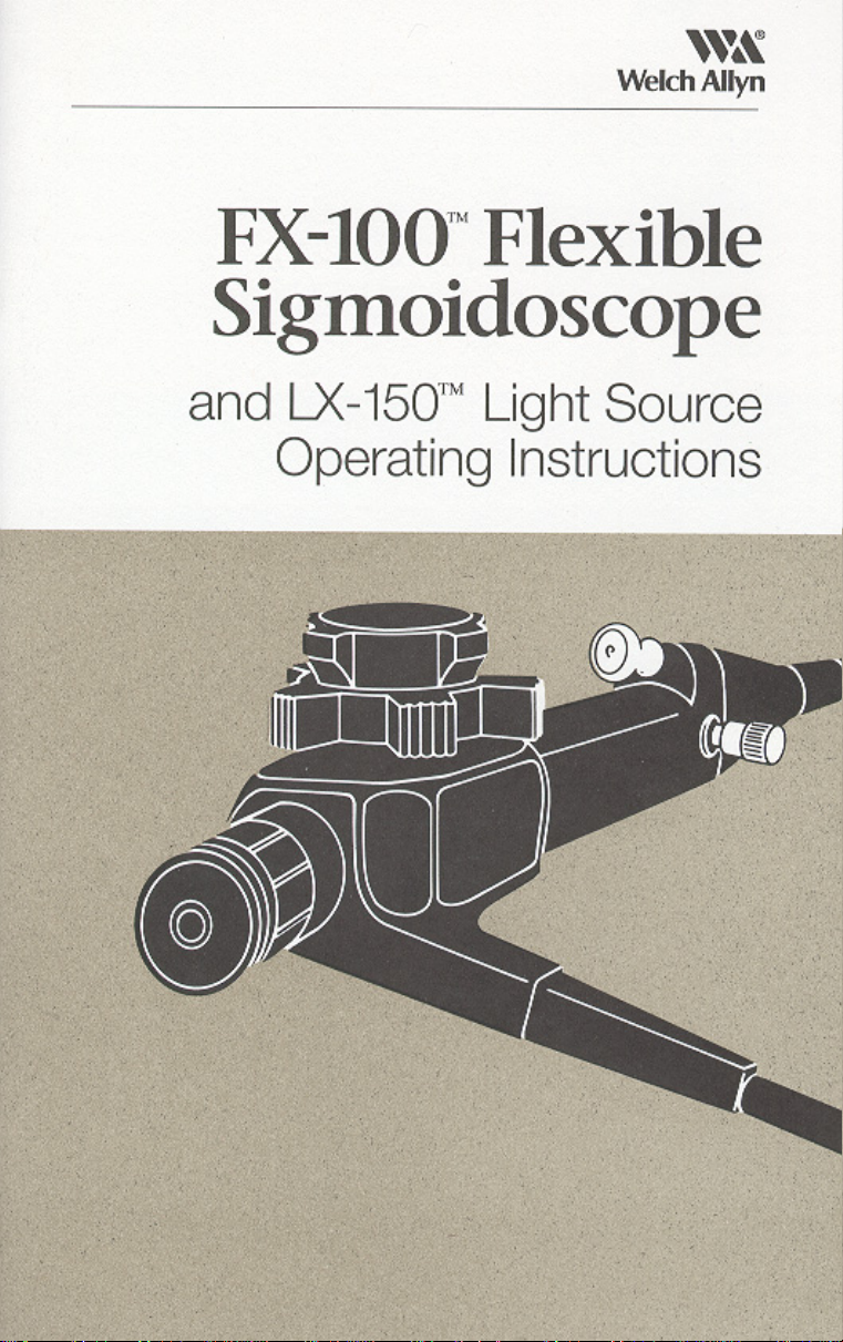
FX-100 Flexible Sigmoidoscope
#33900 Fiber Optic Sigmoidoscope Includes:
FX-100 Fiber optic sigmoidoscope
#33910 Cleaning brushes (2 ea.)
#33911 All channel irrigator
#33919 Air/water disinfection cap
#33930
I.
#33907 Manual irrigation tubing
#33913 Suction tubing
#33908 2 Each
Biopsy seals (10 each)
-
30 cc syringe
4
Page 5
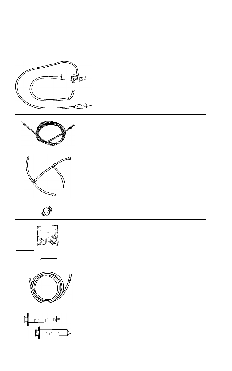
a
#33912 Biopsy cleanout adaptor
#33922 Leakage tester
#33906 Dual lumen air/water line
L
Q >_’
Q
(Actual Size)
c
ir4
#33916 Air/water disinfection line
#33914 Blowout adaptor
#33918
#33924 Air/Water nozzle
#33923
Valve lubricant
cleaning brush
Air/water & suction valve
"O"
rings (12 per bag)
5
Page 6
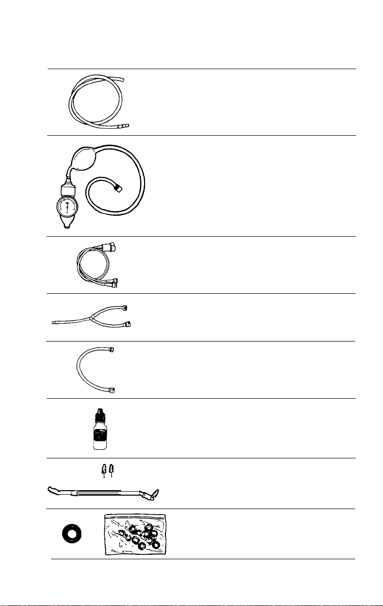
LX-150 Light Source
#45250
1.
2. Water bottle assembly - #33905
3. FX-100 Disinfection Video Tape
Light Source includes:
Light source - LX-150
Water
Bottle
Assembly
J_J
#33905
Adaptor
#45157 CLK-3 Adaptor (Olympus)
Allows the FX-100 to couple to an Olympus CLK-3 light source
CLK-3
AW
Adapter
Olympus CLK-3
Light Source
Allyn
Welch
Water Bottle
6
Page 7
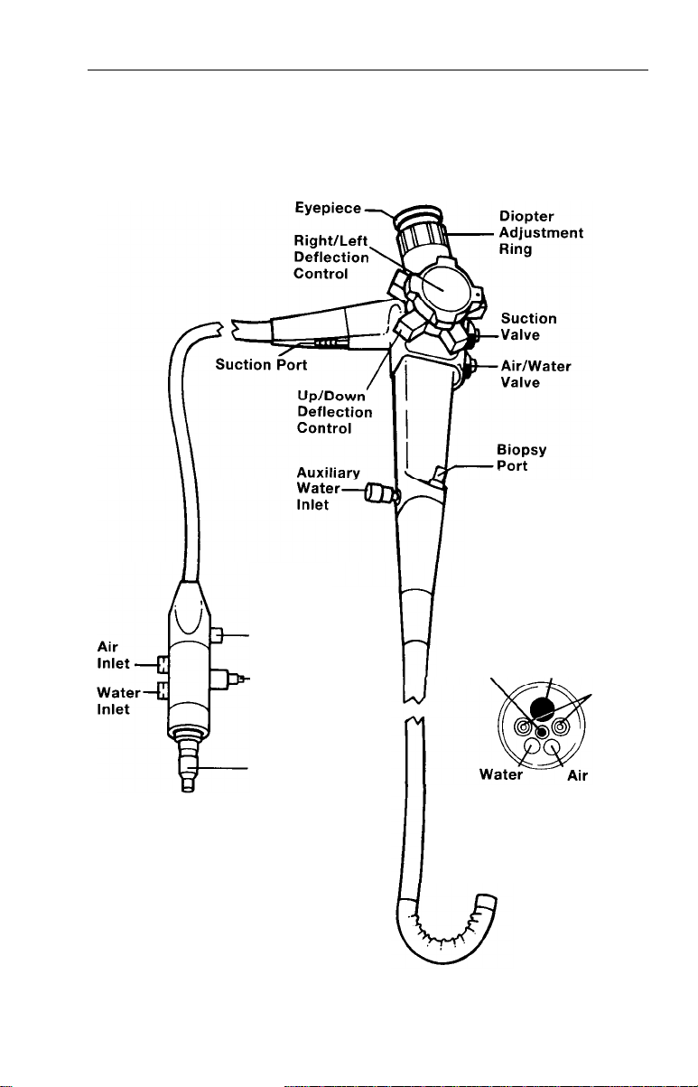
Nomenclature
Fiber Optic Sigmoidoscope
CONTROL
SECTION
ENDOSCOPE
CONNECTOR
TERMINAL
Ground
Cord
Connector
ETO
Vent
Connector
Light Guide
Terminal
Objective Biopsy/Suction
Lens
Nozzle
BENDING SECTION
7
Channel
Light
Guides
Nozzle
DISTAL
TIP
Page 8
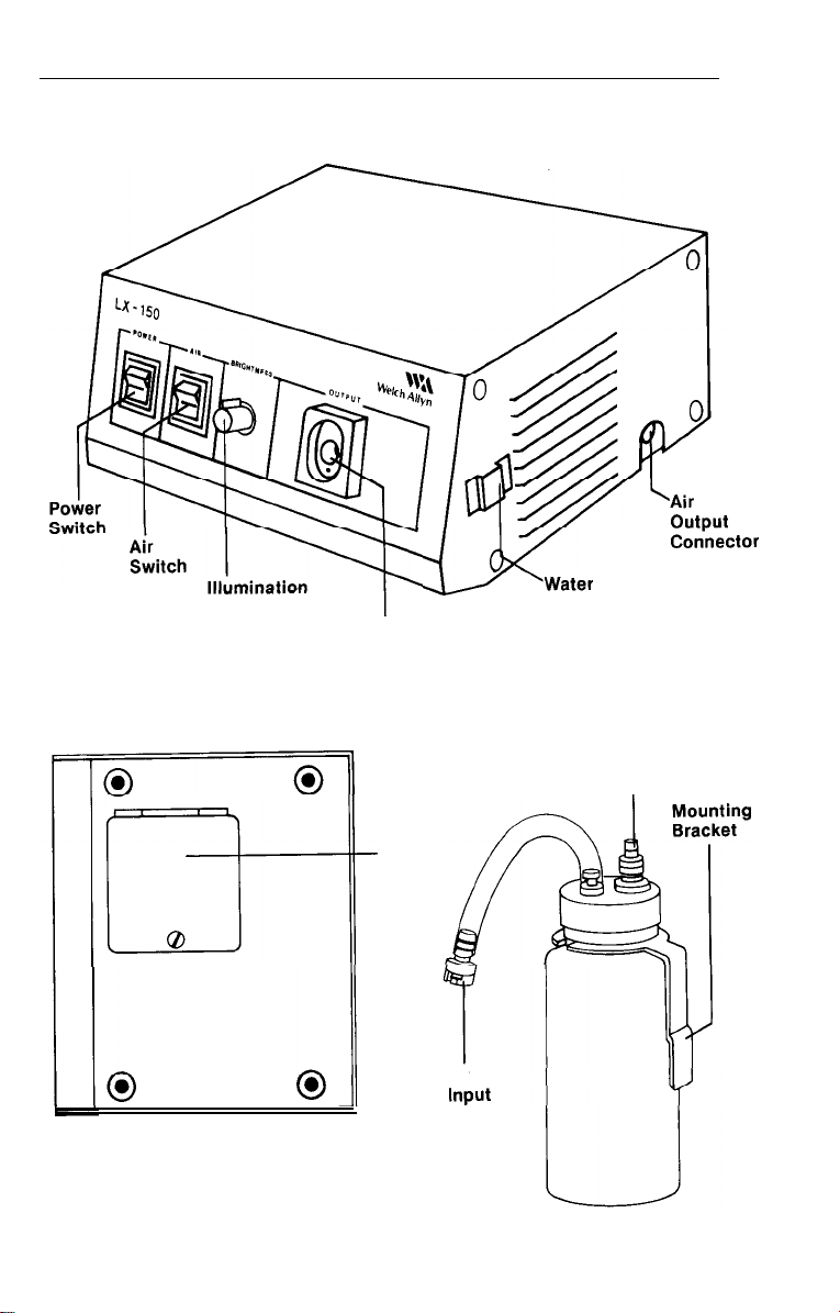
Light Source
Control
,
Mater
Endoscope
Connector Port
Bottle Connector
Bracket
Air/
Water
output
BOTTOM VIEW
Lamp
Access
Door
Air
Hose
WATER BOTTLE
8
Page 9

Prior to Initial Use
9
Before preparation or set up of the equipment, check all components
received against list of components (see components section) to
verify complete set. If parts are missing, please notify Welch
Allyn.
Review the nomenclature, setup, operation and cleaning/disinfection
sections to become familiar with the equipment.
Specifically, inspect:
Fiber Optic Sigmoidoscope
l Insertion tube
l Control section
to assure smooth rotation of controls
l Biopsy channel
channel to verify smooth passage
-
for tears, cuts, dents, bubbles, bumps
-
depress valves, test bending section deflection
-
pass cleaning brush through biopsy/suction
Light Source
l Cabinet
-
for any dents, scratches or other abnormalities
System Setup
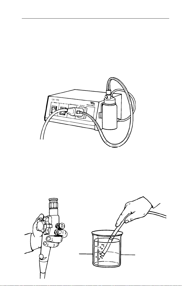
Light Source
Plug the light source into a properly grounded 110-120 volt
AC outlet. Activate power and air switches to verify functionality
of illumination and pump.
Fill water bottle approximately 3/4 full of clean tap water. Replace
and tighten the cap and attach to water bottle bracket on the
right side of light source.
Connect air input hose on water bottle to air output connector on
right side of light source.
9
Page 10
System Setup
Fiber Optic Sigmoidoscope
NOTE:
use, following the steps starting on page 24 and 35, or in the FX-100
cleaning and disinfection video tape.
Endoscope should be cleaned and disinfected prior to initial
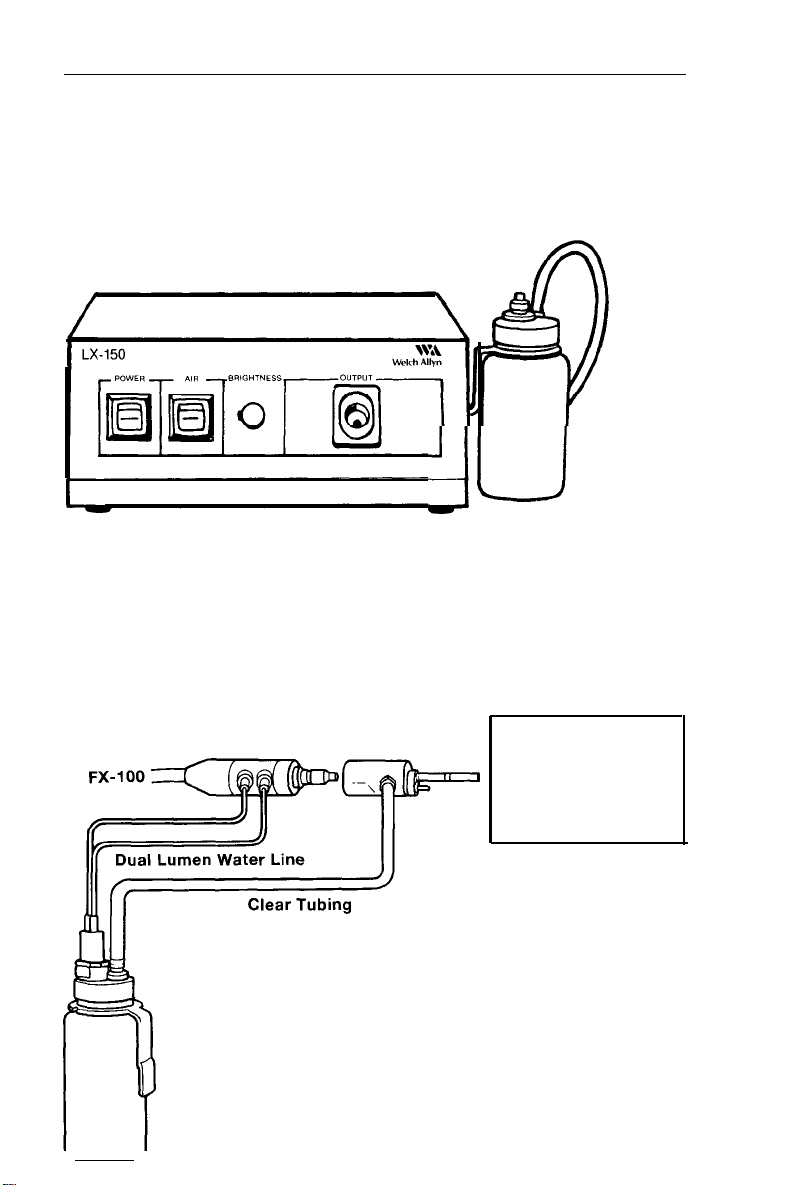
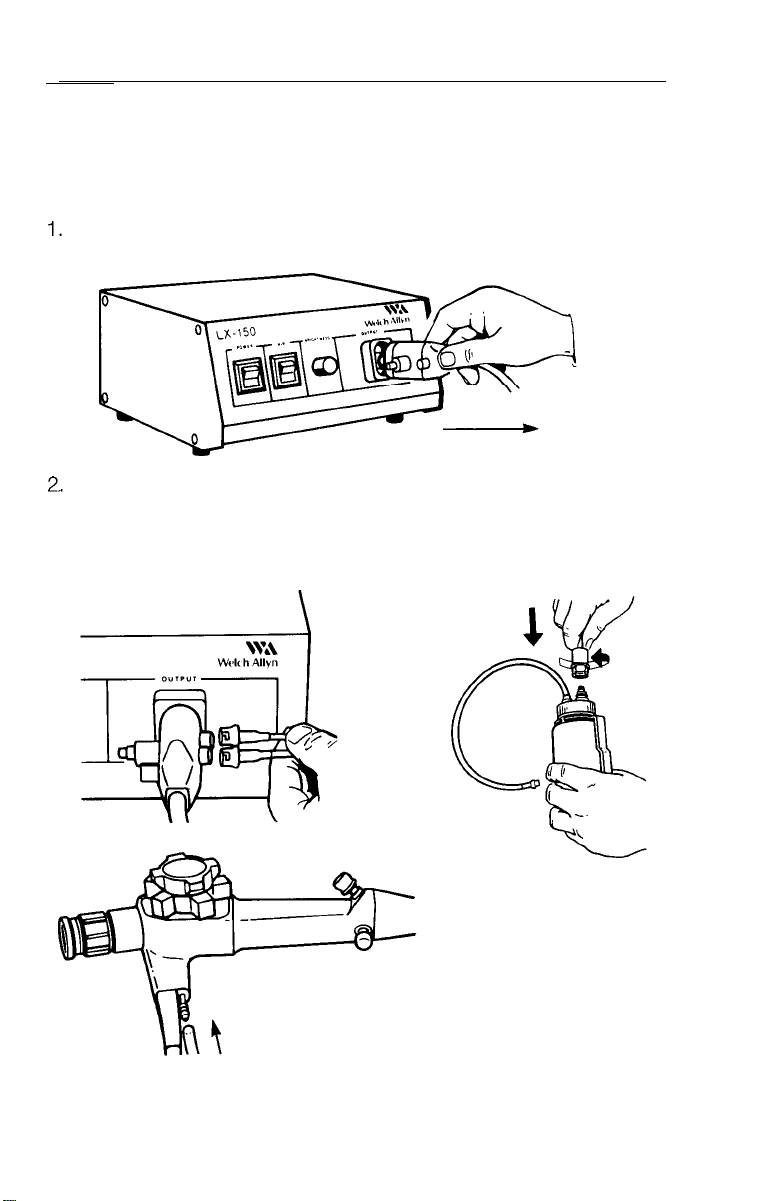
Plug endoscope connector terminal into endoscope connector port
of light source. Push gently until it “snaps” into place.
Connect ends of dual lumen air/water line to the color coded
air/water outputs on endoscope connector terminal (White =
Water, Green = Air). Attach remaining end to water bottle. Mount
3/4 filled water bottle on light source bracket and couple remaining
hose to air output connector.
Connect suction
3.
tube to suction port
on control section.
Attach remaining
end to suction
source receptacle.
4. Verify biopsy seal is seated in place over biopsy port opening.
10
Page 11
System Inspection
The following steps should be repeated prior to every procedure to
verify that the system is working. If any problem is encountered,
immediately consult the troubleshooting section of this manual or
contact your local Welch
assistance.
Physical Inspection:
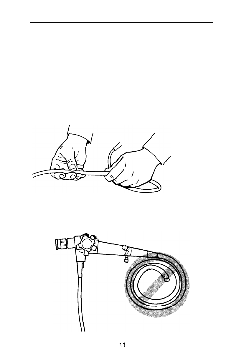
Insertion Tube and Bending Section
l Inspect the insertion tube for tears, cuts, dents, bubbles, bumps
or other abnormalities on the surface.
l
Run your fingers carefully over the entire length to check for
protruding braid, internal looseness or other abnormalities.
Allyn
distributor or representative for
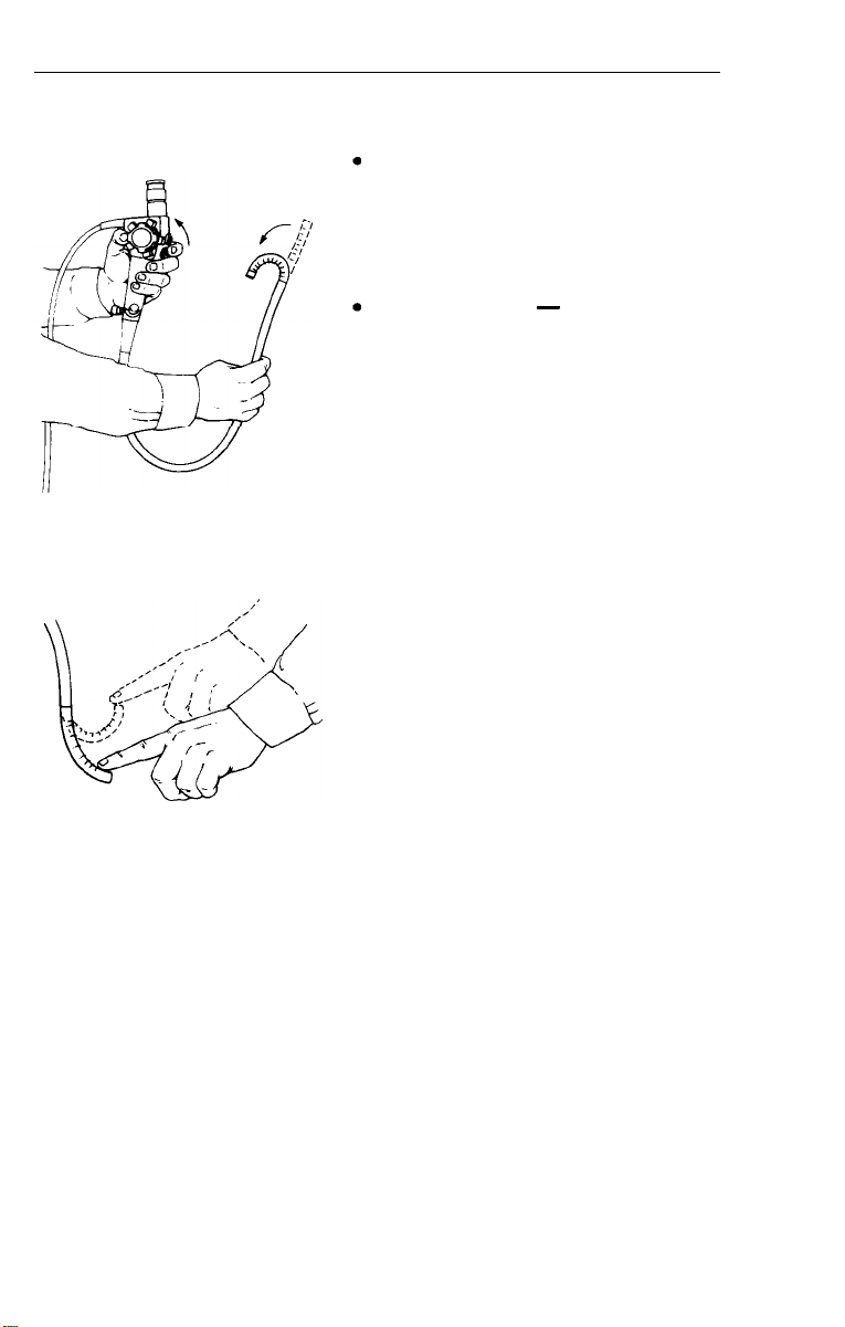
CAUTION: Do not wind insertion tube into a tight radius. Serious
damage to internal fibers could result. Proper storage procedures
are outlined on page 50.
Page 12
Deflection Controls
Operate deflection controls slowly
in all directions. Make sure that
deflection is smooth and that no
friction or grinding is present.
Up/down plane - rotate the up/
down deflection control knob to its
limit in each direction. It should
rotate without excess friction.
l Right/left plane
-
rotate the
right/left deflection control knob to
its limit in each direction. Unlike the
up/down control, a slight resistance
or “drag” should be apparent. This
is a design of the scope that allows
the bending section to remain in
position without holding the control
knob. The bending section should
not lock into position. To verify this,
deflect the control to maximum and
release. The bending section should
return to a straight or neutral posi-
tion by applying gentle pressure with
your index finger.
WARNING: If the resistance in the right/left deflection plane
is higher than normal, DO NOT USE the instrument. Contact
Welch Allyn Customer Service for assistance.
CAUTION: Do not deflect the bending section by hand. This
applies excess force to the deflection mechanism and may
result in failure.
12
Page 13
Light Source
1. Activate “power” switch. This will start the lamp and cooling fan.
CAUTION: Do not look directly into the endoscope connector
port when activating the light source.
2.
The output of the light source is then controlled by the illumination
intensity control. Clockwise rotation will increase illumination
output. Counter clockwise will decrease illumination.
3. Activate “air” switch. This will start the internal insufflation pump.
Inspection of Air Feed
1.
Place tip of bending section into clear water. Cover hole on top of
air/water valve with finger tip. Do not depress valve. Air should flow
freely through the instrument and water should bubble vigorously.
2. Remove finger - bubbling should end immediately.
13
Page 14
Inspection of Water Feed
1.
Depress air/water valve completely. Water should flow in a
constant stream over objective lens and light guides.
2.
Release valve - water flow should end immediately.
NOTE: Upon initial setup, depress and hold down valve for a few
seconds for water to completely fill line in instrument.
Inspection of Suction
1.
Verify that suction tubing is attached and suction machine is on.
Immerse tip of bending section into clear water and completely
2.
depress suction valve.
Verify aspiration by viewing water flow into suction receptacle.
3.
Releasing valve should stop suction immediately.
14
Page 15
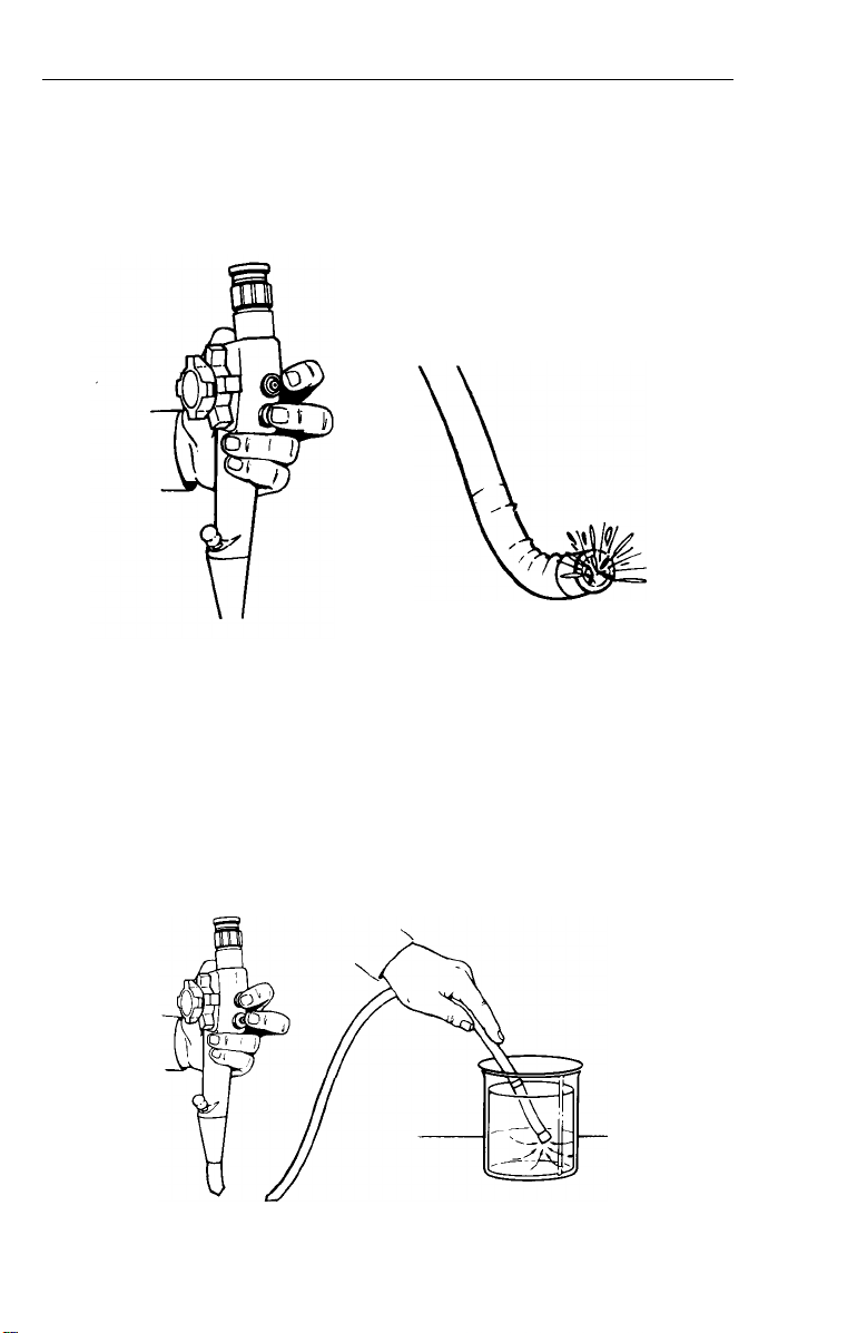
Inspection of Manual
Water Feed
1.
Connect manual irrigation
tubing to auxiliary water
inlet on endoscope.
2. Fill syringe with clean tap
water and connect to
remaining end.
3. Feed water through inlet
and verify that it exits from
water nozzle over objective
lens and light guides.
NOTE: If leak occurs at inlet, tighten connector. If leak
continues, call Welch Allyn Customer Service.
Inspection of Biopsy/Suction Channel
1.
Deflect bending section 90o in “up” direction.
2. Pass cleaning brush or forceps through the
biopsy channel to verify a clear pathway.
3. Repeat Steps "1 and 2” in three remaining
directions.
NOTE: If resistance is encountered, DO NOT force. Contact
Welch Allyn Customer Service.
15
I!=
“0 MB
Page 16
Inspection of Light
Guides and Optics
1.
With lamp on, hold distal tip
approximately 40 mm from
any printed surface.
2. Verify light is being emitted from light guides.
3.
Hold eyepiece to your eye and rotate diopter ring until print is in
focus. Verity focus from 10-40 mm from surface.
Inspection of Umbilical Cord
1.
Check the umbilical cord for cracks, dents, crushed and
twisted areas.
2.
Verify that the endoscope connector terminal’s light guide terminal
fitting is tight and does not move when moderate pressure is
applied.
NOTE:
prior to every use. (Follow steps starting on pages 22 and 47, or
demonstrated in the FX-100 cleaning and disinfection video tape).
Instrument should be cleaned, disinfected and sterilized
16
Page 17

Operations
Procedure
The methods and techniques of flexible sigmoidoscopy are well
defined and documented. Endoscopy training seminars and
preceptorship programs are also in existence worldwide.
No attempt is made in this manual to outline the medical procedure
or techniques of flexible sigmoidoscopy. The physician should always
take care to understand the clinical background of each patient and
the possible contraindications of the procedure.
Holding the Instrument
The control section is designed
for the left hand. The
formed by the left thumb and
index finger should be posi-
tioned beneath the area where
the umbilical cord exits the
control section. The suction
and air/water valves are con-
trolled by the index finger and
middle finger respectively. The
up/down deflection control is
operated by the thumb. The
right hand is used to advance
and rotate (torque) the insertion tube. In some instances,
it may be necessary to have
an assistant hold the insertion
tube while the right/left
deflection control is rotated
by the right hand.
"V"
17
Page 18

Insertion/Operation:
Objective Lens Focusing
l
Hold the distal tip
30-40
mm from a
flat, printed surface.
l
Rest eyepiece on cheek bone of
right eye.
l
Rotate the diopter ring until the
characters are sharp and in focus.
Insertion
l
Prior to insertion, the bending
section and distal portion of the
insertion tube should be lubricated
with a water soluble lubricant.
DO NOT cover the light guides or
objective lens.
l
DO NOT use lubricants that are petroleum based as these will
deteriorate the rubber covering the bending section.
NOTE:
Patient preparation should be adequate so that no fecal
material is present, If prep is poor, discontinue immediately.
NOTE:
If the image during insertion becomes red and out of focus
(a “red out”), this is a sign that the tip is in contact with the mucosal
wall. DO NOT ADVANCE FURTHER. Slowly withdraw the instrument
and gently inflate the colon until lumen is visible.
Light Intensity Adjustment
l
Once lumen is visible, adjust the
light intensity control to desired
setting.
NOTE:
The distal tip of the
sigmoidoscope may become warm,
if in continuous operation with
illumination set too high, and may
I
damage mucosa. Use the lowest
light setting possible.
18
Wkh.UW
U
\C\
U
Page 19

Tip Deflection
l
Slowly operate the deflection controls to guide the instrument
through the lumen
CAUTION: If resistance is encountered, DO NOT force deflec-
tion controls. Doing so may damage the instrument and/or
injure the patient.
CAUTION: DO NOT advance the instrument if lumen is not
visible. Blind advancement could result in perforation.
WARNING: If during the procedure the deflection controls
cease to function, terminate examination. Return both deflection
controls to the neutral position, by rotating the deflection
controls slowly until the “up” and “right” markings on the
control knobs are in line with the eyepiece. Slowly withdraw
the endoscope while viewing through the eyepiece. Do not
operate controls.
Flushing Objective Lens
l
Lubricant, mucous and fecal materials can cloud or fog the
objective lens. The lens can be cleared by depressing the
air/water valve.
l
If a more forceful wash is required, attach the manual irrigation
tubing to the auxiliary water inlet and flush with a syringe filled
with clean tap water.
l
Water drops retained on the lens can be removed by covering
the hole on top of the air/water valve.
Suction
l
Fluid, secretions, and liquid stool can be aspirated by depressing
the suction valve.
l
Aspiration will also remove excess air introduced during insufflation
CAUTION: Care should be taken to avoid sucking mucosa into
the channel. This phenomena can result in a “suction polyp”
that can be mistaken for a lesion.
19
Page 20

Insufflation
l
A collapsed lumen can be opened by insufflation. Cover air/water
valve to inflate colon. Adequate insufflation can be maintained by
insufflation and aspiration of air.
CAUTION: DO NOT overinflate the colon. This may cause
severe patient discomfort as well as inhibit insertion.
Biopsy Passage
l
Biopsy forceps and accessories should
be inserted through the biopsy seal and
into the channel.
l
The forcep should be advanced using
short strokes, started by grasping the
forcep sheath no more than 4 cm from
the channel opening.
WARNING: If resistance is encountered
during passage through the bending
section, relax deflection angle until
passage is smooth and easy. Wetting the forcep with water or a
medical grade silicon lubricant will promote easier passage.
l
If biopsy seal “spits” or leaks while instrument is in place, remove
defective seal and replace.
NOTE: When replacing biopsy seal,
rotate one full turn clockwise after
pushing on luer-loc fitting to insure
a proper seal.
NOTE: Always flush biopsy channel
immediately after a procedure by
aspirating clear water through the
channel (see cleaning). This will assist
passage of instruments in subsequent
procedures.
Obtaining a Biopsy
l
Collect tissue sample by opening forcep and advancing open cups
up against the mucosa. Close cups slowly until resistance is
and then hold. Gently pull back on forcep until small tissue sample
is removed.
WARNING: DO NOT open forcep until biopsy cups are out of
the biopsy channel and can be visualized. Doing so may damage
biopsy channel.
CAUTION: DO NOT exert excess force when closing forcep.
Such action may damage forcep.
20
felt,
Page 21

l
Always
withdraw
cups in a closed position.
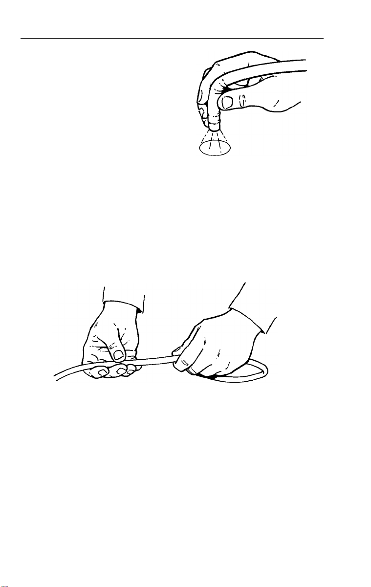
NOTE: If forcep fails to close during
a procedure, close cups by winding
the proximal portion of the forcep
cable around your index finger. If
forcep still does not close, withdraw
cups as close as possible to the
distal tip and slowly withdraw the
instrument under direct visualization.
forcep
with the
Electrosurgery
Warning:
Before attempting endoscopic electrosurgery, the operator should
be thoroughly trained and versed in the technique and be knowledgeable of the risks associated with the procedure. There have been
reported cases of
ration. Therefore, any preparation that does not evacuate and clean
the bowel entirely, is a contraindication to this procedure. Medical
experts agree that this procedure is extremely hazardous if performed
with an enema prep only. However, if performing an electrosurgical
procedure through the flexible sigmoidoscope, the S-cord should be
attached to the sigmoidoscope and the remaining end to the chassis
of the electrosurgical generator.
colonic
explosion due to inadequate bowel prepa-
Electrosurgery Connections
Remove safety cap from ground
cord connector.
Connect the S-cord’s terminal nut to
the ground cord connector on the
endoscope connector terminal.
Secure the other end to the chassis
of the electrosurgical unit.
To reduce the risk of electric shock,
both physician and assistant
should wear rubber gloves.
DO NOT turn electrosurgical generator on until just prior to use.
I
21
Page 22

Cleaning and Disinfection
Endoscopic instruments should be cleaned immediately after each
use. Endoscopes are delicate and will degrade if not cleaned
promptly, due to the effects of digestive contents - blood, mucous,
etc. The methods outlined on the following pages have been tested
and verified to have no damaging effects. Therefore, these procedures
should be adhered to.
NOTE: Cleaning and Disinfection Program - The complete cleaning
and disinfection process has been videotape recorded to assist you
in learning the correct way to care for your instrument. The video tape
and accompanying laminated guide is included with the light source
in the top of the shipping box. If you did not purchase a light source
and would like Welch
Customer Service at l-800-535-6663.
Supplies Needed (for cleaning and disinfection)
Large basin of water
1.
Cleaning solution (soap solution)
2.
Gauze pads
3.
Disposable gloves
4.
Cleaning brush*
5.
Leakage tester*
6.
Biopsy
7.
2 Each - 30 cc syringe*
8.
Air/water nozzle cleaning brush*
9.
Blowout adaptor*
10.
cleanout
Allyn
to send you a video tape, please call
11. All channel irrigator*
12. Air/water disinfection line*
13. Air/water disinfection cap*
14.
Isopropyl alcohol
15.
Cotton Swabs
16.
Suction tubing*
17.
adaptor*
Suction machine
18.
Valve lubricant*
19. Soft bristle brush
22
Page 23

10
c
-55
11
U
17
*This component is included with the FX-100 Sigmoidoscope
12
15
1
18
16
19
@
13
23
Page 24

Cleaning
Immediately After Procedure...
1.
With instrument still coupled to suction machine, insert distal tip into
clean water and depress suction valve.
Aspirate until water running through suction line is clear.
Turn off suction device and disconnect suction line.
2. Turn off “air” and “power” switches on light source. Disconnect dual
lumen air/water line from air and water inlets on endoscope connector terminal.
NOTE:
water bottle to drain any water in the line back into the bottle. If not
performed, the siphon created by the water system under pressure
will force the water through the open connectors. Tie the line in a loose
knot on too of the water bottle to avoid any dripping.
After disconnecting, elevate air/water line above the top of the
24
Page 25

3.
Remove the instrument from the light source by grasping the
endoscope connector and pulling back gently.
4.
Place the insertion tube into soap solution and scrub the insertion
tube lightly with a gauze pad dampened in soap solution.
5.
Remove the air/water valve (identified by two blue rings on the top
of the valve), grasp and pull up, place into soap solution. Replace
the valve with the air/water disinfection cap. Gently brush the air and
water nozzles in the distal tip with a soft brush to dislodge any debris.
Take care not to push any debri back into the air and water lines.
Disinfection Cap
25
Page 26

6. Locate the air/water disinfection line and
attach the side with two fittings to the air
Air/Water
Disinfection Line
and water inlets on the endoscope connector terminal. Fill a 30 cc syringe with
clean water and couple it to the remaining end. While holding down the air/water
disinfection cap with a finger, inject water
through the air/water lines until it sprays
from both nozzles in the distal tip.
n
Uncouple the syringe from the tubing.
7
The next step is to purge the water that was just introduced into
the air and water lines. This can be accomplished using one of the
following two methods:
Refill the 30 cc syringe with air. Re-couple to the air/water disin-
A)
fection line and inject air to purge the system. Repeat. Disconnect the syringe and air/water disinfection line.
OR
Couple the single end of the air/water disinfection line to the
B)
blowout adaptor. Re-seat the instrument’s connector terminal
into the connector port of the light box. Attach the free end of the
blowout adaptor to the air output connector on the side of the
light source. Activate light source “power” and “air” switches.
Hold down the air/water disinfection cap to blow both the air
and water lines dry. Continue for approximately 15 seconds.
Turn the switches on the light source to the “off” position and
disconnect all lines and the instrument from the light source.
Air/Water
Disinfection
Line
Steps A and B achieve the same results --- simply choose the step
that you can best incorporate into your routine for cleaning.
26
Page 27

8.
Perform Leak Test Procedure.
two stage test of the watertight integrity of the instrument. Air
pressure is introduced into the interior of the instrument by means
of a hand pump. The instrument is then checked for pressure decay
via a gauge and then visually.
The leakage test allows for a simple
Stage 1
BEFORE IMMERSION, the instrument should be tested for any
major loss of integrity in its watertight construction (example: major
tear in the bending section).
A. Secure the Leakage Tester to the
instrument’s endoscope connector terminal. The Leakage
Tester connector and the ETO vent connector MUST be dry
before securing. To properly connect, align air vent pin,
depress and rotate clockwise.
ETO
vent connector on the
27
Page 28

B. Pressurize the inside of the instrument by pumping the hand
bulb until the indicator needle on the gauge is within the
“TEST” zone. DO NOT pressurize into the “DANGER” zone;
doing so may result in serious damage to the instrument.
NOTE: Make sure that the pressure release valve on the back of the
gauge is closed.
Pressure
Release Valve
NOTE: The rubber covering the bending section will expand. This
indicates an increase in internal pressure and is normal.
C. Observe the gauge indicator needle to determine if the indicator
remains in the “TEST” zone. If the indicator drops out of the
“TEST” zone rapidly, a major leak in the instrument is indicated.
NOTE: Be certain that the pressure release valve has been
tightened.
DO NOT proceed to Stage II Test, if the indicator needle does
not remain in the “TEST” zone. Instead, contact Welch
Allyn
Customer Service.
28
Page 29

Stage
29
After determining the absence of any major leak in Stage I testing,
the instrument may be immersed in clean water to test for loss of
integrity in the watertight construction due to small pin hole leaks.
A. With the Leakage Tester securely attached to the instrument
and the gauge indicator needle in the “TEST” zone, the entire
instrument may be immersed in clean water.
II
NOTE:
its tubing should be immersed. NEVER immerse the entire Leakage
Tester.
B.
Only the Leakage Tester connector and a small portion of
Observe the instrument carefully. A few bubbles may initially
rise from recessed areas of the scope. This is normal. If a continuous stream of bubbles is observed from the same spot, a leak
is indicated. Immediately remove the scope from the water.
DO NOT attempt to use the instrument for a procedure. Clean
and disinfect the instrument to the best of your ability without
immersing it and call Welch
l-800-535-6663.
Allyn
Customer Service at
29
Page 30

9. After removing the instrument from water, release the air
pressure by opening the pressure release valve on the handle of
the Leakage Tester. After the gauge indicates “ZERO”, disconnect the Leakage Tester from the scope.
NOTE:
NEVER connect or disconnect the Leakage Tester under
water. This will cause leakage of water into the instrument and
Leakage Tester.
10.
Remove suction valve (identified by two red rings on the top of
the valve) and white biopsy seal by grasping and pulling upwards.
Place them in soap solution to soak.
Biopsy
Seal
30
Page 31

Biopsy
Port
Clean
out
Adaptor
w
12.
Place the distal end of the instrument and the other end of the
cleanout adaptor into the soap solution. Activate suction machine
and cover the open suction valve well with a finger to aspirate soap
solution through the biopsy/suction channel in all directions.
Continue for about 10 seconds. Turn off suction machine and
disconnect all tubing.
Page 32

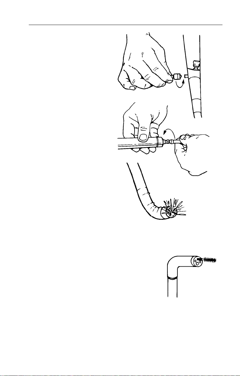
13. Insert a cleaning brush through biopsy/suction pathways in
three directions:
a. Insert cleaning brush into the suction valve well perpendicular
to the top of the control section. Advance the brush until it
emerges from the suction port. Remove any debris from the
brush with a gauze pad, and remove the brush by pulling
back through the instrument.
b. Insert the cleaning brush into the open biopsy port and
advance for about 6 to 10 inches. Remove the brush and
clean any solid debris off the tip using a gauze pad.
c. Insert brush back into suction valve well, angle it 45 degrees
toward the distal tip and advance until it exits the biopsy/
suction channel opening in the distal tip. Remove all debris
from the tip of the brush with a gauze pad soaked in soap
solution and pull back to remove.
A
NOTE: If brush will not pass-DO NOT force. Disinfect instrument to
the best of your ability and contact Welch
Allyn
Customer Service at
l-800-535-6663.
WARNING: Forcing brush through can damage the suction
channel.
32
Page 33

14. Place the entire instrument into soap solution and gently brush all
external surfaces with a soft bristled brush. Brush the air/water inlet
nozzles with the air/water nozzle brush across the nozzle openings,
take care not to push any debris back into the air and water line.
Gently scrub the valves and biopsy seal with a soft bristle brush.
r\/
15.
Remove instrument from soap solution and reattach suction
line. Place instrument, valves and biopsy seal into clean water.
Rinse thoroughly.
NOTE:
Rinse valves thoroughly as residue can cause valve to stick.
16.Turn on suction machine. With instrument immersed in clean water,
cover open suction valve well with finger to aspirate clean water
through the channel to rinse. Continue for approximately 15 seconds.
17. Lift entire instrument out of basin of water and, with the suction
valve well still covered, aspirate air through biopsy/suction line
for 60 seconds to dry channel.
33
Page 34

18. Disconnect suction line, dry exterior
of instrument thoroughly. Dry the valves
and biopsy seal and set aside.
19. Reattach the air/water disinfection line
to the air and water inlets on the in-
strument’s connector terminal.
Air/Water
Disinfection Line
20.The
next step is identical to step #7 and it’s purpose is to
thoroughly dry the lines. This can be accomplished using one of the
following two methods:
A) Refill the 30 cc syringe with air. Re-couple to the air/water disin-
fection line and inject air to purge the system. Repeat.
Disconnect
the syringe and air/water disinfection line.
OR
B) Couple the single end of the air/water disinfection line to
the blow-out adaptor. Re-seat the instrument’s connector
terminal into the connector port of the light box. Attach the free
end of the blowout adaptor to the air output connector on the
side of the light source. Activate light source “power” and “air”
switches. Hold down the air/water disinfection cap to blow both
the air and water lines dry. Continue for approximately 15 seconds.
Turn the switches on the light source to the “off” position and
disconnect all lines and the instrument from the light source.
-
Steps A and B achieve the same results
simply choose the step that
you can best incorporate into your routine for cleaning.
The instrument is ready for sterilization/disinfection.
Air/Water
Disinfection
Line
Page 35

Disinfection
The Welch Allyn flexible sigmoidoscope is manufactured from a variety
of special materials which optimize instrument performance, but may
not withstand some disinfection solutions and methods.
l
Prior to disinfection, flexible endoscopes should be thoroughly cleaned
and dried following the methods previously defined. Incomplete or
improper cleaning will decrease the effectiveness of solution exposure.
l
Welch Allyn cannot recommend a disinfection solution on the basis of
germicidal effectiveness.
WARNING: All instruments and accessories must be thoroughly
rinsed after exposure to disinfection solutions. This removes all
toxic residue and will prevent patient irritation and instrument
degradation.
Solution exposure times for disinfection should be verified with
solution manufacturer.
The materials listed below are considered safe for use with the
Welch Allyn flexible sigmoidoscope if used according to manufacturer’s instructions for disinfection and in accordance with the
following methodology.
These solutions are extremely aggressive, and failure to follow the
disinfection cycles precisely, including initial cleaning and final
rinsing, may result in shortening instrument life.
Recommended Cold Disinfecting Solutions
Glutaraldehyde (2.0% only)
Banicide Wavicide-01
Metricide Zorbicide
Cidex
WARNING: DO NOT use solutions that are oil based or contain
a surfactant (such as Cidex 7 or Cidex Plus). Additionally, bleach
solutions will permanently damage metal components of the
instrument.
NOTE:
To inquire about compatibility of the flexible sigmoidoscope with
disinfection solutions not listed, please call Welch Allyn customer service.
35
Page 36

Disinfection Tray
1.
Fill the disinfection tray’s clear tube with disinfectant to the black
indicator dot on the top of the tube.
2. Fill a small covered container with additional disinfection solution
and place the suction and air/water valves and biopsy seal into
the container to soak.
NOTE:
3. Connect the all channel irrigator.
Air/water disinfection cap is still attached to the instrument,
A) Seat the black rubber suction valve well adaptor into the open
suction valve well. Push down to snap the connector into place.
B) Connect the silver luer-lock to the open biopsy port.
C) Push free tubing onto the suction port.
D) Connect a 30 cc syringe to the luer-lock fitting on the all
channel irrigator.
36
Page 37

4.
Connect the air/water disinfection line to the inlets on the
endo-
scope connector terminal. Fill a 30 cc syringe with disinfectant from
the covered container and connect the syringe to the end of the
tubing.
Air/water
Disinfection Line
5.
Slide insertion tube into the tray’s tube filled with disinfection solution
and position the instrument’s control section securely in the space
provided on the tray.
37
Page 38

6.
Carefully wind the umbilical cord and place in the provided space on
the tray. The attached syringes and tubing can hang over the side.
Pull back on the plunger of the empty syringe (connected to the
all channel irrigator) to aspirate disinfectant into the instrument’s
biopsy/suction channel. Continue until the syringe is half full (15 cc).
Leave the syringe connected and partially filled for the duration of
the soak cycle (usually 15-20 minutes, refer to solution manufacturer’s recommended time).
Hold down on the air/water disinfection cap and depress plunger
of the syringe connected to the air/water disinfection line. Continue
until fluid exits from the nozzles in the distal tip (i.e., until bubbling
from tip stops, or the syringe is half full). Leave syringe connected
for duration of soak cycle (usually 15-20 minutes, refer to the manufacturer’s recommended time).
After soaking for the disinfectant solution manufacturer’s recom-
mended time, depress the plunger on the syringe connected to
the all channel irrigator to expel solution.
10. Remove the syringe coupled to the air/water disinfection line and
inject the remaining solution into the small covered container.
11. To purge all remaining solution, remove both syringes, fill them
with air, reconnect, and one at a time, inject air into the channels.
NOTE: Remember to hold down the air/water disinfection cap when
injecting with the syringe coupled to the air/water disinfection line.
12. Detach the all channel irrigator and remove the instrument from
the tray.
38
Page 39

13. Place the insertion tube into a basin of clear water. Attach suction
line to the suction port and the biopsy
cleanout
adaptor to the open
biopsy port.
Suction
Biopsy
Clean out
Adaptor
M
Port
14. Place the suction and air/water valves and biopsy seal into the
basin of clean water to rinse.
15.
With distal tip of the instrument and free end of the cleanout
adaptor under water, activate the suction machine and cover the
open suction valve well with your finger to aspirate water through
the entire biopsy/suction channel to rinse. Continue for approximately 10-15
Page 40

16. Disconnect syringe attached to the air/water disinfection line, fill with
clean water, reattach to tubing, and inject water to rinse the air and
water lines. Repeat this 2-3 times to thoroughly rinse the channels.
17.The
next step’s purpose is to thoroughly dry the lines. This can be
accomplished using one of the following two methods:
A) Refill the 30 cc syringe with air.
Re-couple to the air/water
dis-
infection line and inject air to
Air/Water
Disinfection Line
_
I
purge the system. Repeat.
Disconnect the syringe and
air/water disinfection line.
OR
B) Couple the single end of the air/water disinfection line to the
blowout adaptor. Reseat the instrument’s connector terminal
into the connector port of the light box. Attach the free end of the
blowout adaptor to the air output connector on the side of the
light source. Activate light source “power” and “air” switches.
Hold down the air/water disinfection cap to blow both the air and
water lines dry. Continue for approximately
15
seconds. Turn the
switches on the light source to the “off” position and disconnect
all lines and the instrument from the light source.
-
Steps A and B achieve the same results
simply choose the step that
you can best incorporate into your routine for cleaning.
Terminal Port
Air/hater
Disinfection
Line
40
Page 41

18. Disconnect the air/water disinfection line and biopsy
cleanout
adaptor
19. Wipe off the exterior of the instrument with a gauze pad moistened
in clean water.
20. Lift the insertion tube out the basin. Cover the open suction valve
well and aspirate air through the channel to dry.
21
.Turn
off the suction machine, disconnect the suction line and dry
the instrument’s exterior.
22. Remove the valves and biopsy seal from the water and dry.
23.Apply a thin coat of valve lubricant to the valve’s
"O"
rings and
reseat them in the open valve wells. Reseat the biopsy seal.
24. Wipe off exterior of instrument with a gauze pad moistened in
isopropyl alcohol. Clean distal lens with cotton swab dipped in
isopropyl alcohol.
//
25. Hang scope with insertion tube straight to air dry.
Page 42

Disinfection - Immersion
1.
Fill covered basin with disinfectant to a level that will allow the entire
instrument to be immersed in solution.
2.
Place the air/water and suction valves and biopsy seal into solution
to soak.
NOTE:
3. Connect the all channel irrigator.
Air/water disinfection cap is still seated in the air/water valve well.
A) Seat the black rubber suction valve well adaptor into the open
suction valve well.
B) Connect the silver luer-lock to the open biopsy port.
C) Push end of remaining free tubing onto the suction port,
D) Connect a 30 cc syringe to the luer-lock fitting in the all channel
irrigator
42
Page 43

4.5.Connect the air/water disinfection line to the air and water inlets on
the endoscope connector terminal. Fill a 30 cc syringe with disinfectant and connect to the remaining end of the line.
Air/Water
Disinfection Line
Place the insertion tube and distal tip into the disinfection solution
while holding down the air/water disinfection cap, and depress the
plunger of the syringe connected to the air/water disinfection line.
Continue until the bubbles emerging from the air and water nozzles
(distal tip) stop (usually 15 cc of solution).
43
Page 44

6.
Immerse the entire instrument in the disinfectant, with the exception
of the syringes coupled to the all channel irrigator and the air/water
disinfection line.
7.
Draw back on the plunger of the syringe connected to the all
channel irrigator until all lines of the irrigator are filled with solution
(usually until syringe is half full).
Allow the instrument to soak in the disinfection solution for the
8.
manufacturer’s recommended time (usually around 15-20 minutes).
After the soaking, depress the plungers of both syringes to purge
9.
remaining disinfectant. Remove both syringes and fill with air, reconnect. Depress the plungers, one at a time, to force air through the
channels to purge the disinfectant. Repeat until clear.
NOTE: Remember to hold down the air/water disinfection cap when
injecting with the syringe coupled to the air/water disinfection line.
1
0. Remove
the instrument from the disinfectant and detach the all
channel irrigator.
11. Attach suction line to suction port and place instrument into a basin
of clean water.
12.To
rinse the air and water lines, disconnect the syringe coupled to
the air/water disinfection line. Fill with water, reattach, and while
holding down the air/water disinfection cap, depress the plunger
to inject water into the lines. Repeat 2-3 times.
44
Page 45

13.Remove
the syringe and air/water disinfection line and place the
endoscope connector tubing into the basin to rinse.
14. Place air/water suction valves and biopsy seal into the water to
rinse.
15.
Activate suction machine (suction line attached to suction port) and
while the instrument is underwater, cover open suction valve well to
aspirate water through the line to rinse. Continue for around 15
seconds.
16. Wipe down exterior of instrument in clean water to rinse off any
residual solution.
17. Lift the entire instrument out of the water and cover the open valve
well with a finger to aspirate air through to dry the channel.
18.Turn
off suction machine, disconnect the suction line, and dry the
exterior of the instrument.
45
Page 46

19. Lift the air/water and suction valves and biopsy seal from the water
and dry.
20. Apply a thin coating of valve lubricant to the valve’s “0” rings and
reseat them in the open valve wells.
21.
Wipe off exterior of instrument with a gauze pad moistened in
isopropyl alcohol. Clean distal lens with cotton swab dipped in
isopropyl alcohol.
22. Hang instrument with the insertion tube straight to dry.
46
Page 47

Sterilization
Thorough mechanical cleaning and drying of the flexible sigmoidoscope are prerequisites to sterilization. If gas sterilization is required,
the instrument should be sterilized following the methodologies
outlined below:
NOTE:
result in severe damage.
DO NOT steam autoclave the instrument. Doing so will
Procedure
1. Remove suction, air/water valves, biopsy seal prior to exposure.
ETO
2. Attach the
3. DO NOT exceed 130°F or 10 psi.
4. Remove vent cap prior to next procedure.
NOTE:
temperature is 7 days.
Gas exposure not to exceed 4 hours. Aeration time at room
vent cap (accessory) to the instrument.
47
Page 48

Troubleshooting Chart
Symptom Possible Cause Solution
Image is
not clear.
Inadequate
suction.
Eyepiece not Turn focus adjusting ring
adjusted to user’s
eyesight. is in sharp focus.
Distal objective
obscured.
Lenses dirty.
Water damage
to lens.
Suction valve
blocked.
Biopsy seal is worn.
Suction channel
blocked.
Suction pump not
on or tubing
disconnected.
(diopter ring) until fiber pattern
Rinse lens by injecting water
through auxiliary water inlet.
Remove scope and clean distal
objective and eyepiece with
cotton swab and alcohol.
Return scope to Welch Allyn
Service for evaluation/repair.
Remove valve, clean valve and
housing with a cleaning brush.
Lubricate
lubricant and replace.
Replace biopsy seal.
Call Welch Allyn Service
Department for instructions.
Verify good connection
between suction pump and
scope. Turn pump on.
"O"
rings with valve
No
insufflation.
Air pump not
turned on.
Air tubing not connected or pinched.
Air nozzle blocked.
Turn air pump on. Test scope
for air flow.
Verify that the dual lumen air/
water lines are securely attached.
Verify that water bottle input
connector is coupled to light
source.
Soak tip of scope in warm soapy
water for 2-3 minutes. Gently
brush with air/water nozzle cleaning brush. Connect dual lumen
disinfection
warm water through air/water
lines while cycling air valve. If
nozzle remains blocked, contact
Welch Allyn Customer Service.
48
line.
Gently inject
Page 49

Symptom Possible Cause Solution
No
Insufflation.
Water bottle cap not Tighten cap.
secured tightly.
(cont’d.)
Cannot
Water bottle empty.
Fill water bottle.
irrigate.
Water bottle cap not
Tighten cap.
secured tightly.
Suction
valve
sticks.
Dirty valve stem. Remove valve; clean valve and
housing with cotton swab and
alcohol; lubricate "O"rings with
valve lubricant and replace.
Biopsy seal Biopsy seal is worn. Replace biopsy seal.
“spitting”
or leaking.
Insufficient
articulation
Loose articulation
knob.
Return scope to Welch Allyn
for adjustment.
of tip.
Return scope to Welch Allyn
for adjustment.
Turn illuminator on and adjust
Return scope to Welch Allyn
Inadequate
illumination.
Degree of articulation
is less than specified.
Illuminator not
turned on. light to appropriate intensity.
Damage to light
transmitting fibers. for evaluation/repair.
Illuminator Not plugged into
not working.
electrical outlet. grounded outlet.
Lamp is
burned out.
Fuse is blown.
49
Plug illuminator into 120 volt
Replace lamp according to
instructions.
Call Welch Allyn
Service Department.
Page 50

Maintenance and Storage
Maintenance:
Suction and Air/Water Valves
l
Both suction and air/water valves should be inspected weekly.
To remove, pull up on ring around valve stem to remove from
its well.
l
Clean each valve well with a succession of pipe cleaners until
last cleaner is clean and dry (DO NOT use cotton tipped applicators).
Air/Water and Suction Valves
1.
Inspect valve stem.
"O"
2. Look closely at
3. If cracked or worn, replace.
4. To remove
"O"
rings into place over base of valve stem.
"O"
rings.
rings, grasp with tweezer and remove. Roll new
NOTE: Remove top
valve stem.
5.
Lubricate valves by reapplying a light coat of silicone lubricant to
"O"
rings.
"O"
ring first before those at the base of the
Biopsy Seals
To Seat:
clockwise.
To Remove:
To Flush Channel:
luer-lock fitting.
Disinfection/Sterilization:
products and alcohol.
NOTE:
lubricant can be injected into the chamber directly behind top
opening. This will ease entry of instrument into and through
biopsy channel.
Push seal onto luer-lock fitting and rotate one full turn,
Pull seal while rotating counterclockwise.
Remove seal and connect syringe directly to
Seal is compatible with all glutaraldehyde
To ease insertion of instruments, silicon or a water soluble
50
Page 51

Lens Cleaning
Moisten cotton-tipped applicator with 70% isopropyl alcohol.
Clean debris from objective lens and light guides.
NOTE: DO NOT use abrasive materials to clean lens. Doing so
could scratch and permanently damage optics system.
Storage
l Flexible sigmoidoscope should be stored with insertion tube and
umbilical cord as straight as possible. If coiling is necessary,
insertion tube and umbilical cord should not be wound in more
than one loop.
l Flexible sigmoidoscope should not be stored in areas exposed to
temperature extremes or high humidity. Storage area should be
dry and clean.
Other manufacturers’ accessories should be stored per their
recommendations.
Service
Customer Service
Telephone Assistance:
l-800-535-6663
For repairs on the FX-100, ship to:
Welch
Allyn
Repair Department
4341 State Street Road
Skaneateles Falls, NY 13153
51
Page 52

 Loading...