

Page 1

Operating Manual
Electrosurgical Unit
Operating Manual
Page 2

Electrosurgical Unit • Instruction Manual
1
Electrosurgical System
TABLE OF CONTENTS
I. Professional Use Guide . . . . . . . . . . . . . . . . . . . . . . . . . . . . . . . . . . . . . . . .2
II. System Features . . . . . . . . . . . . . . . . . . . . . . . . . . . . . . . . . . . . . . . . . . . . .10
III. Electrical Precautions . . . . . . . . . . . . . . . . . . . . . . . . . . . . . . . . . . . . . . . . .14
IV. Placement of the Patient Plate . . . . . . . . . . . . . . . . . . . . . . . . . . . . . . . . . .16
V. Foot Pedal Switch . . . . . . . . . . . . . . . . . . . . . . . . . . . . . . . . . . . . . . . . . . . .16
VI. Power Connection, Electrode Connection & Power-Up . . . . . . . . . . . . . . . .16
VII. Operation . . . . . . . . . . . . . . . . . . . . . . . . . . . . . . . . . . . . . . . . . . . . . . . . . .17
VIII. Safety Circuits . . . . . . . . . . . . . . . . . . . . . . . . . . . . . . . . . . . . . . . . . . . . . .17
IX. Practical Suggestions . . . . . . . . . . . . . . . . . . . . . . . . . . . . . . . . . . . . . . . . .17
X. Cleaning . . . . . . . . . . . . . . . . . . . . . . . . . . . . . . . . . . . . . . . . . . . . . . . . . . .17
XI. Periodic Safety Checks . . . . . . . . . . . . . . . . . . . . . . . . . . . . . . . . . . . . . . . .18
XII. Troubleshooting . . . . . . . . . . . . . . . . . . . . . . . . . . . . . . . . . . . . . . . . . . . . .19
XIII. Liability Statement . . . . . . . . . . . . . . . . . . . . . . . . . . . . . . . . . . . . . . . . . . .20
XIV. Warranty . . . . . . . . . . . . . . . . . . . . . . . . . . . . . . . . . . . . . . . . . . . . . . . . . .21
Manufactured for:
Welch Allyn, Inc.
4341 State Street Road
Skaneateles Falls, NY 13153
Phone: 315-685-4560
Phone: 800-535-6663
Fax: 315-685-4653
Page 3

IMPORTANT
Thoroughly train the user of this equipment, in the techniques of loop electrosurgical excision procedures. This equipment is designed for use with Electrosurgical
Accessories. DO NOT use this equipment for any purpose other than that for which
it is designed.
This manual contains information about the proper procedures for inspecting and
preparing the equipment before its use and its care and storage after use.
This manual does not describe actual procedure is performed, nor is it meant to
teach the proper technique or any of the medical considerations regarding the use
of this equipment. Welch Allyn recommends that prospective user obtain appropriate training before using this equipment as improper use is potentially hazardous to
the patient and the user. DO NOT use this device without proper training.
Training in the use of electrosurgical equipment should include:
1. A review of the published literature regarding the procedure of interest.
2. Attendance at a course or courses offered by Physicians experienced
with the loop electrosurgical excision procedure.
3. Hands-on preceptor training from an experienced practitioner.
PLEASE READ THIS ENTIRE MANUAL CAREFULLY TO BECOME FAMILIAR
WITH EACH OF THE CONTROLS AND FEATURES BEFORE MAKING ANY
ATTEMPT TO USE THE EQUIPMENT CLINICALLY.
FOLLOW INSTRUCTIONS CONTAINED IN THE OPERATING MANUALS OF ANY
EQUIPMENT USED IN CONJUNCTION WITH THIS EQUIPMENT TO AVOID ANY
POSSIBLE HAZARD FROM INCOMPATIBILITY.
FAILURE TO THOROUGHLY UNDERSTAND AND FOLLOW THE INSTRUCTIONS
GIVEN IN THIS MANUAL MAY RESULT IN SERIOUS INJURY TO THE PATIENT
AND/OR THE OPERATOR. FAILURE TO FOLLOW THE INSTRUCTIONS GIVEN IN
THIS MANUAL MAY RESULT IN DAMAGE TO OR MALFUNCTION OF THIS
EQUIPMENT.
No long-term follow-up studies with this device have been performed as to recurrence rates. The effects of loop electrosurgical excision procedure on pregnancy
outcome are not known.
ALWAYS EXERCISE SAFETY PRECAUTIONS WHEN USING ELECTRICAL
EQUIPMENT TO PREVENT OPERATOR/PATIENT SHOCK, FIRE HAZARD AND
EQUIPMENT DAMAGE.
CAUTION: U.S. Federal law restricts this device to sale by or on the order of a physician. This device SHOULD NOT be used without proper training and preceptorship.
If any questions arise regarding the information contained in this manual, the
operation or safety of the equipment or service, please contact your local
Distributor or Welch Allyn Customer Service at 1-800-535-6663.
I. PROFESSIONAL USE GUIDE
2
Electrosurgical Unit • Instruction Manual
Page 4

3
A. INDICATIONS
The loop electrosurgical excision procedure is indicated in the diagnosis and treatment of some Cervical Intraepithelial Neoplasia (CIN) in patients where there is:
• cytological or colposcopic suspicion of CIN 2 or worse (including micro-invasion)
• persistent CIN 1 (of more than 12 months duration)
• CIN 1 where the likelihood of follow-up is low or when the patient requests
treatment
• a transformation zone which is fully visible and fully confined to the cervix
• a suspicion (cytological or colposcopic) of a glandular intraepithelial abnormality
• a disparity between the cytological and colposcopic diagnoses
• external anogenital lesion
• large vaginal intraepithelial neoplastic (VAIN) lesions
• cervical conization indications
B. CONTRAINDICATIONS
The following are typical contraindications for performing the loop electrosurgical
excision procedure. It is imperative that the physician carefully weigh the risks and
benefits of treatment versus non-treatment in contraindicated patients:
• pregnancy
• apparent invasive carcinoma of the cervix
• a bleeding disorder
• acute or active inflammation of the cervix, endometrium, fallopian tube, ovary or
peritoneum (cervicitis, endometritis, tubo-ovarian inflammatory disease or
pelvic inflammatory disease)
• “positive” endocervical curettage or a lesion in which the endocervical limit is
not visualized colposcopically
• less than 3 months postpartum
• DES-exposed patient with known or suspected cervical changes
• equivocal cervical abnormality
C. LOOP ELECTROSURGICAL EXCISION PROCEDURE PROCEDURE AND TECHNIQUE
It is recommended that the patient is provided with a brief description of the procedure and the equipment is used in this procedure (ACOG and other professional
organizations and equipment manufacturers have produced patient information
brochures on the loop electrosurgical excision procedure that address many of the
questions and concerns that your patients may have regarding the procedure).
D. SAFETY PRECAUTIONS
1. Only a thoroughly trained physician should use this equipment in an adequately
equipped medical facility.
2. Keep replacement accessories and patient return pads on hand since defective
active accessory or patient return pads can result in sub-standard performance
of this equipment.
Electrosurgical Unit • Instruction Manual
I. PROFESSIONAL USE GUIDE (cont.)
Page 5
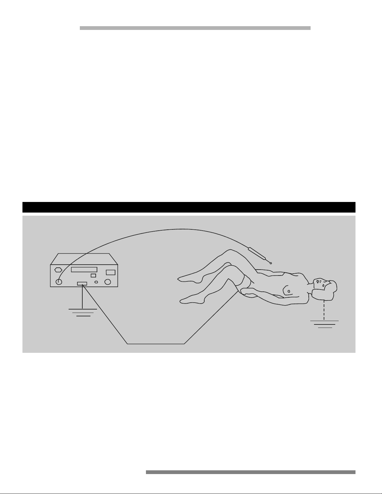
PROPER
Generator
RF current through
patient to return pad
Active Electrode
Grounded
Metal Case
Patient
Two conductor patient
electrode continuity
monitor
Patient return pad
(Thigh)
Patient may be
grounded
3. Only connect this equipment to a properly grounded receptacle. NEVER use an
adapter that defeats the ground of the built-in three (3) prong plug.
4. Exercise care when handling liquids around electrical equipment. DO NOT
attempt to operate this equipment if liquids have spilled on the unit. DO NOT
use flammable liquids around electrical equipment.
5. Never use this equipment in conjunction with other equipment for which safety against leakage current is not established.
6. When this equipment is operated:
a. Use a properly attached Patient Return Pad (dispersive pad) of adequate sur-
face area to the patient or the risk of accidental burns will exist.
b. Place the Patient Return Pad (dispersive pad) as close as possible to the site
of use of the active accessory but NEVER placed so that the patient’s heart
is in the pathway from the active accessory to the return electrode!
7. The user should thoroughly understand the principles and use of radio frequency (RF) current before using this equipment. This understanding is essential to
avoid the hazard of shocks or burns to the user and/or the patient.
I. PROFESSIONAL USE GUIDE (cont.)
4
Electrosurgical Unit • Instruction Manual
Page 6
5
8. Follow the instructions for use described in this manual; otherwise, compromised safety, malfunction, injury to the operator and/or patient, or costly damage to the unit may occur.
9. There are no user-serviceable parts within the housing. Only authorized Welch
Allyn service personnel can perform repairs to this equipment. For service
information, please contact Welch Allyn Customer Service at 1-800-535-6663.
I. PROFESSIONAL USE GUIDE (cont.)
Electrosurgical Unit • Instruction Manual
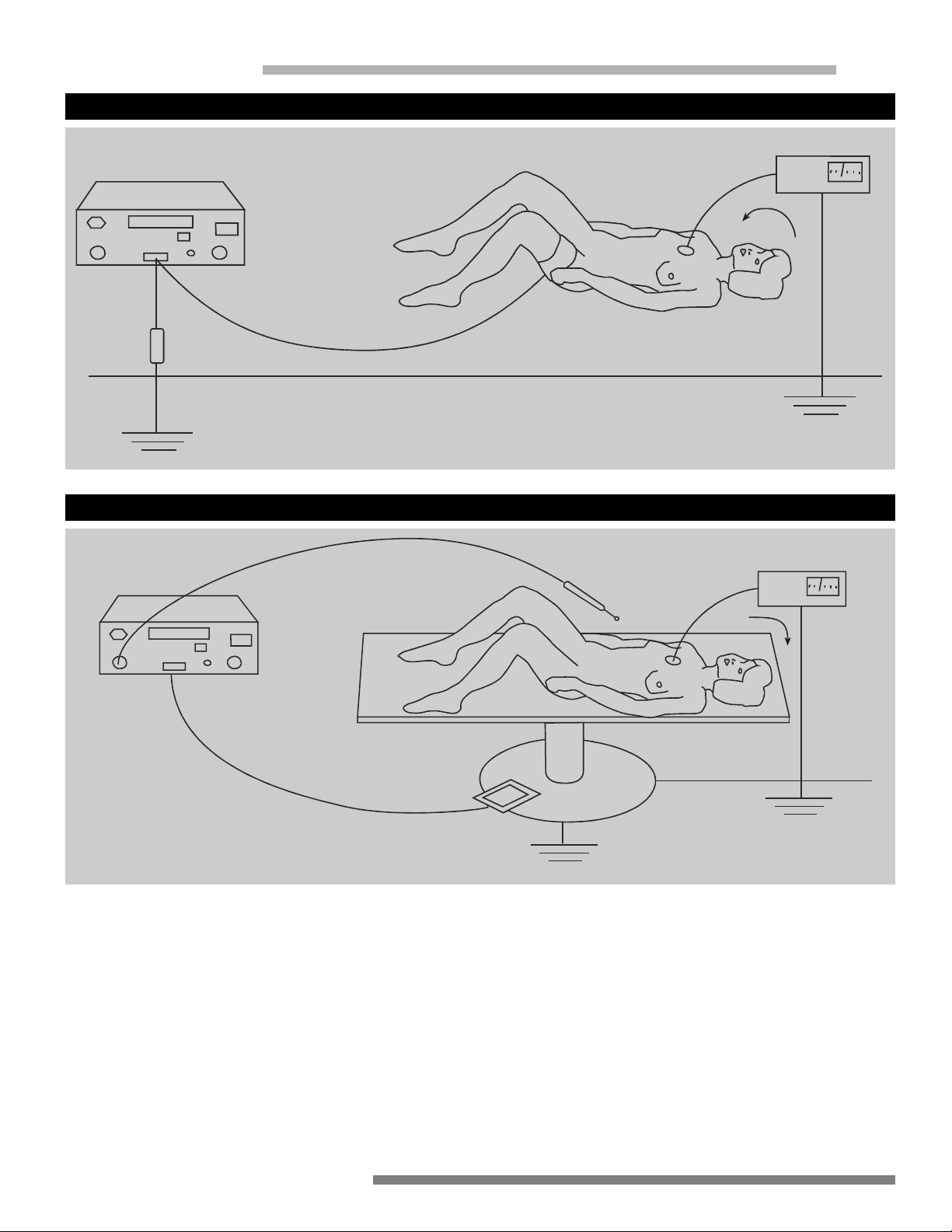
IMPROPER
Generator
Burn occurs at small
grounded contact
Surgeon touches electrode
to grounded object
Isolated
ESU
RF current flows from ground
through EKG pad, through
patient to return pad
IMPROPER
Generator
RF current flows
from electrode
Burn occurs at small
grounded contact
Isolated or
grounded ESU
Patient return pad touches
grounded table
RF current returns to patient
return pad via ground path
EKG
RF
RF
EKG
Page 7

E. ELECTROSURGICAL PROCEDURES
This section provides only general information about the use of electrosurgical devices.
Only the User can evaluate the clinical factors involved with each patient and determine
if the use of this equipment is indicated. The User must then decide on the specific technique and procedure that will accomplish the desired clinical effect.
WARNING
Electrosurgical generators are designed to allow the controlled destruction
of tissue and are inherently dangerous if operated improperly.
REPORTED PROBLEMS DUE TO IMPROPER OPERATION DURING
ELECTROSURGICAL PROCEDURES HAVE INCLUDED:
Inadvertent activation with resultant tissue damage at the wrong site and/or
equipment damage.
Alternate current pathways resulting in burns where the patient or physician
or assistant is in contact with exposed metal.
Explosions caused by electrosurgical sparking in a flammable gas mixture
(i.e., explosive anesthetic gases and the inappropriate use of alcohol and
other flammable liquids).
Perforation and massive hemorrhage.
A proper patient return pad pathway is extremely important during any
monopolar electrosurgical procedure. Ensure every effort is made throughout the electrosurgical procedure, an adequate surface area is provided and
remains in proper contact with the patient to reduce the current density
below a level that might cause inadvertent tissue damage where the patient
return pad is applied.
I. PROFESSIONAL USE GUIDE (cont.)
6
Electrosurgical Unit • Instruction Manual
Page 8

7
1. SETTING THE CONTROLS
a. Electrosurgical Tissue Effect
Delivery of continuous sinusoid waveform currents through a small electrode at appropriate power levels can cause rapid heating of the intracellular fluids in the cells in close proximity to the electrode, turning these fluids
to steam. The significant increase in volume (approximately 5 times) causes cellular structure to rupture, creating the clinical effect of “CUT”, with little or no hemostatic effect along the margin of the divided tissue. Delivery
of short duration pulses of RF currents through a small electrode at appropriate power levels can cause heating of intracellular fluids at a more gradual pace. This allows evaporation of these fluids without rupturing the cellular structure, creating the clinical effect of desiccation, or “COAG”, without
the division of tissue. By varying the pulse to an intermediate duration, it is
possible to get a clinical effect that combines, or “blends”, the clinical characteristics of CUT and COAG yielding the effect referred to as “BLEND”,
where tissue is divided with a desirable amount of hemostatis along the
margins of the divided tissue.
The electrosurgical effect may vary throughout the procedure, requiring the
operator to adjust the relative power setting of the generator.
b. Select the output mode (i.e., “CUT”, “BLEND”, or “COAG”) by pushing the
corresponding buttons.
Output Mode Waveform Description General Effect
CUT Continuous 450 KHz sinusoid Cutting without Hemostatis
with minimal modulation
BLEND Interrupted 450 KHz sinusoid Cutting with minimal
intermediate duty cycle Hemostatis
COAG Bursts of 450 KHz sinusoid Coagulation without Cutting
short duty cycle
c. Set the level of output power (confirmed on the digital display) by using the
output power selector buttons as desired.
WARNING
The degree and speed of electrosurgical effect is largely dependent on Current Density at the point of contact of the active electrode. Loop electrosurgical excision procedure electrodes from other manufacturers may vary
in the diameter thickness, size and configuration of the cutting wire. This
may result in SIGNIFICANT changes in the electrosurgical effect at a given
output power level setting. The use of Welch Allyn Electrodes is recommended.
I. PROFESSIONAL USE GUIDE (cont.)
Electrosurgical Unit • Instruction Manual
Page 9

d. If the use of other output modes is anticipated, repeat steps (a) and (b) as
desired. The output power level settings selected for each output mode are
retained as long as the unit remains ON.
2. GUIDELINES FOR POWER SETTINGS
The following guidelines for power settings may vary due to the technique, clinical circumstances, accessory style, cutting wire diameter, size, configuration
and user preference.
NOTE: * If the cut mode is desired, use the recommended settings for the
blend mode.
+ As required, increase the power setting beyond 56 to coagulate
any bleeding points.
REMEMBER, THIS IS NOT AN ATTEMPT TO TEACH ELECTROSURGICAL TECHNIQUE.
Inexperienced practitioners should not attempt the procedures described below
based solely on this information; instead, acquire the skills required in the time-honored preceptor manner. NOTE: The best initial effect is accomplished with the cutting wire in only light contact with tissue. Tight pressure may cause desiccation of
the tissue and will delay the start of the cutting effect.
IMPORTANT
The initial use of any electrosurgical generator always involves some degree
of “trial and error”. This is true even when only changing from numbered
dials to digital display models within the same manufacturer’s product line.
As with any other therapeutic device, it is very helpful to experiment IN
VITRO or on animal sample tissue before using any electrosurgical generator or methods which are not familiar.
The microprocessor control system of this unit was developed specifically
to provide the best possible performance for Loop electrosurgical excision
procedures. By exhibiting patience and following the guidelines offered, the
practitioner should easily become familiar with the performance characteristics of the Electrosurgical Unit.
I. PROFESSIONAL USE GUIDE (cont.)
Recommended Power Settings (Watts)
for the Welch Allyn Electrosurgical Electrodes
8
Electrosurgical Unit • Instruction Manual
1.0
22-36
1.5
30-40
2.0
34-36
40-56
Macro
+
30-36
Micro
14-24
Page 10

9
3. TECHNIQUE GUIDANCE
a. When performing the procedure, the endocervix is commonly not included
in the excision, and the results of endocervical curettage are not predictive
of either residual or invasive disease after loop electrosurgical excision procedure.
b. Loop electrosurgical excision procedures performed with small diameter
wire loop electrodes may produce multiple small pieces of cervical tissue,
and provide a less acceptable tissue specimen for histopathologic analysis.
The influence of electrode design on procedure effectiveness is not completely understood.
c. Larger lesions involving multiple quadrants of the cervix are more difficult to
remove with either the small or large diameter loop electrodes.
4. SMALL DIAMETER LOOP VS. LARGE DIAMETER LOOP
The histological quality of specimens obtained using small diameter electrodes
is inferior to specimens obtained using large diameter loops due to the increase
contact area between loop and tissue epithelium. While the design of the Welch
Allyn Electrodes wais chosen to optimize specimen quality, operative technique
must take these differences into consideration. Reports of clinical evaluations
of small diameter electrodes describe thermal damage which precluded histological evaluation of approximately 3% of the tissue specimens. In addition,
since multiple, often irregular, strips of epithelium are excised from the cervix,
it is often difficult for the pathologist to orient the specimens for optimal
histopathological examination.
5. THERMAL EFFECTS ON TISSUE TREATED WITH LOOP ELECTRODES
Thermal effects on tissue specimens may include (i) thermal coagulation injury
of the cervix, up to one-third the thickness of normal epithelium of the cervix,
(ii) fragmentation of squamous epithelium of the cervix attributable to long exposure periods along the excision site that allows heat to dissipate laterally, and (iii)
partial coagulation of the endocervical epithelium because of lateral radiation of
heat. Therefore, the loop electrosurgical excision procedure may produce thermal effects at the periphery of the excised tissue and may make histopathologic interpretation difficult or impossible and not allow accurate diagnosis and
need for further treatment.
I. PROFESSIONAL USE GUIDE (cont.)
Electrosurgical Unit • Instruction Manual
Page 11

• Microprocessor controlled for increased precision, accuracy, repeatability, and safety.
• Adequate power for all monopolar electrosurgical procedures.
• Accurate selection of discrete power levels.
• Digital display of output power levels.
• Choice of radio frequency wave forms including CUT, BLEND, and COAG to
accommodate subtle differences in technique and accessory performance.
• Patient plate continuity monitoring with audible alarm.
• Distinct audible tones for CUT/BLEND modes and COAG mode with associated
MODE light.
• Fully regulated isolated output power.
• Meets or exceeds IEC 601-2-2, second edition.
• Non-electric pneumatic foot pedal to maximize safety.
• Disposable patient plate.
• Disposable handpiece.
• Disposable electrodes.
• Output power safety audible alarm with automatic power shut off.
• Class 1, type BF, protected for use with defibrillator.
• Membrane switching to maximize cleanliness and ease of use.
CONTROLS
1. Main switch
2. Socket for pedal switch
3. Socket for active electrodes
4. Socket for neutral electrode
5. Warning light of neutral
electrode alarm (red)
6. Coagulation light (blue)
7. Pure cut and blend light (yellow)
8. Mode control:
9. Power control
II. SYSTEM FEATURES
1 2 8 9 3 4
765
Pure Cut
Blend Cut
Coag
10
Electrosurgical Unit • Instruction Manual
Page 12

Classification I Type BF protected against defibrillator effects
Floating output circuit
Cautions, consult this manual for safety precautions
Pedal connection
Active handle connection
Patient plate connection
High voltage
ELECTRICAL
INPUT VOLTAGE:
95 - 135 VAC 50/60 Hz 190 - 250 VAC 50 Hz
CURRENT: 2.3 amps max. 2.3 amps max.
LOW FREQUENCY LEAKAGE: Less than 50 micro-amps Less than 50 micro-amps
FUSES: 2.5 amps, T type 1.6 amps, T type
POWER CORD: American Cord Set, Hospital Grade,
NEMA 5-15P/IEC 320 Female, 250cm Long
PHYSICAL
Dimensions: 305mm x 267mm x 115mm Weight: 7.250 Kg
ELECTROSURGICAL OUTPUT
RF Output Frequency: 450 kHz
RF OUTPUT POWER: Volts p-p Max Duty Crest
(open circuit) Cycle Factor
CUT 0-100 watts RMS* 830 --- 1.4
BLEND 0-100 watts RMS* 1200 60% 2.0
COAG 0-80 watts RMS* 3800 10% 5.5
NOTE: *stable to >800 ohms (calibration at 500 ohms)
RF ISOLATION: less than 150 milli-amps at 200 ohms
CLASSIFICATION . . . . . . . . .I-Type BF
OUTPUT CIRCUIT . . . . . . . .Floating output. Protected against the effects of the
defibrillator.
WORKING MODE . . . . . . . .Discontinuous maximum duty cycle: 10/30 sec.
COOLING . . . . . . . . . . . . . .Convection cooling without fan
CONTROL . . . . . . . . . . . . .Foot pedal operated (pneumatic) with audible signals
and mode lights
Electrosurgical Unit • Instruction Manual
11
II. SYSTEM FEATURES (cont.)
Page 13

AUDIBLE SIGNALS AND LIGHTS FOR OPERATION AND ALARM:
MAIN . . . . . . . . . . . . . . . . . . . . . . . . . . . .green light
ALARM, PATIENT PLATE CONTINUITY . . .low pitch intermittent audible alarm
- red light
ALARM, OUTPUT POWER . . . . . . . . . . . .higher pitch intermittent audible alarm
CUT AND BLEND MODES . . . . . . . . . . . .low pitch audible signal - yellow light
COAGULATION MODE . . . . . . . . . . . . . . .high pitch audible signal - blue light
NOTE: Specifications subject to change.
OUTPUT POWER AT 500 OHMS
PURE CUT . . . . . . . . . .100 W RMS (open circuit 830 Vp-p; crest factor 1.43)
Waveform: sinusoidal at 450 KHz
BLEND CUT . . . . . . . .100 W RMS (open circuit 1200 Vp-p; crest factor 2) Wave-
form: sinusoidal at 450 KHz
Duty cycle: 60%
COAGULATION . . . . . .80 W RMS (open circuit 3800 Vp-p; crest factor 5.5)
Waveform: sinusoidal at 450 KHz
Duty cycle: 10%
Output Power Diagrams according to PAR.6.8.3 (IEC 601-2-2)
Tolerance: 20% according to PAR.50.2 (IEC 601-2-2)
II. SYSTEM FEATURES (cont.)
12
Electrosurgical Unit • Instruction Manual
Page 14

13
II. SYSTEM FEATURES (cont.)
Electrosurgical Unit • Instruction Manual
Page 15

The safety and effectiveness of electrosurgery is dependent upon the skill of the
operator. It is important that the operator read, understand, and follow the operating instructions supplied with the Welch Allyn Electrosurgical System and thoroughly understand the principles and use of radio frequency (RF) electrosurgical systems.
WARNING: Electrosurgery uses radio-frequency energy to cut and coagulate tissue. Due to the sparking and heat associated with electrosurgery do not use with
flammable anesthetics, or other flammable gases, near flammable fluids or objects
or with oxidizing agents.
• DO NOT use electrosurgery in the presence of flammable gases, flammable liquids, or flammable objects in oxygen enriched atmospheres, nitrous oxide (N20)
atmosphere or in the presence of other oxidizing agents.
• Prevent accumulation of oxygen, nitrous oxide (N20), and flammable gases, under
surgical drapes, or within the area where electrosurgery is performed, and avoid
it in case of thorax or head operations unless safely aspirated.
• Verify that all oxygen connections are leak-free before and during the use of
electrosurgery.
• DO NOT use electrosurgery in the presence of naturally occurring flammable
gases which may accumulate in body cavities such as the bowel.
DO NOT use electrosurgery in the presence of flammable liquids, such as skin
prepping agents. Avoid pooling of flammable liquids near the electrosurgery
site or in human body cavities such as the umbilicus or vagina.
• DO NOT place the electrosurgery active electrode near or in contact with flammable materials, such as cotton, wool or gauze. The active electrode is hot from
use and can cause fire.
• It is possible that the radio frequency can interfere with the electronic circuitry
in the pacemaker. To reduce the risk locate the patient return electrode as close
as possible to the treatment site and ensure that the current path between the
surgical site and the patient return electrode is as far removed from the heart as
possible. For the gynecology procedures locate the patient return electrode on
the patient's upper thigh or under buttocks. Always monitor pacemaker
patients during surgery. In case of doubt ask the pacemaker manufacturer
and/or cardiology department.
• In case of loss of power, turn the system off.
• The possibility exists that the radio frequency can interfere with other medical
equipment when the electrosurgical system is operating. To reduce the interference, physically separate the device, utilize different electrical outlets that are
hospital grounded, do not allow cables to come in contact with each other, and
utilize shielded devices where possible.
• Adjust the fixed output power level to the lowest power setting that will successfully complete the procedure. Refer to the following recommended power
settings for the Welch Allyn Electrodes.
III. ELECTROSURGICAL PRECAUTIONS
14
Electrosurgical Unit • Instruction Manual
Page 16

15
The above power settings are for reference only and can vary based on specific situations and the experience of the operator.
NOTE: * If the cut mode is desired, use the recommended settings for the
blend mode.
+ As required, increase the power setting beyond 56 to coagulate
any bleeding points.
• Avoid skin to skin contact, for instance between the patient's arm and body, by
the placement of an appropriate separating device such as two to three inches
of dry gauze. This will reduce the potential for alternate site burns.
• If monitoring, stimulation, imaging or similar devices are used simultaneously
with electrosurgery, place the monitoring electrodes as far as possible from the
electrosurgery site and the patient return electrode. Position the patient return
electrode close to the electrosurgery site, for example, on the thigh when treating the cervix. NOTE: Monitoring needle electrodes are not recommended.
• Connect the electrical cord of the generator to a properly grounded receptacle.
Do not use extension cords and/or adapter plug.
• Place the connecting cables to the electrosurgery electrodes so that they do not
come in contact with the patient, other cables, or cross each other.
• Remove any metal items from the patient: for example, rings, chains, etc.
• Use accessories supplied by Welch Allyn; they are specifically designed for the
Electrosurgical Unit.
• Do not use old or worn accessories.
When using the electrosurgical system, it is very important that all the current delivered to the patient returns correctly to the unit via the dispersive patient plate only.
• Position the patient correctly on the operating table. The patient and operator
must not come in contact with any metal conductive surfaces.
III. ELECTROSURGICAL PRECAUTIONS (cont.)
Electrosurgical Unit • Instruction Manual
1.0
22-36
30-40
34-36
30-36
14-24
40-56
+
1.5
Macro
Micro
2.0
Recommended Power Settings (Watts)
for the Welch Allyn Electrodes
IV. PLACEMENT OF THE PATIENT PLATE
OR DISPERSIVE ELECTRODE
Page 17

• The patient plate must securely contact a vascular area close to the operating
site. For a gynecology procedure the preferred sites are the patient's thigh (disposable adhesive pads) or under the patient's buttocks (reusable metal plate).
Assure the contact area is clean, free of body lotions, shaved, and massaged for
good circulation. Maximize the contact area of the patient plate and frequently
check for uniform contact during the procedure, especially if the patient has
moved or if liquids have contacted the patient plate. A CONDUCTIVE GEL IS
RECOMMENDED. NEVER place the patient plate so that the patient's heart is
in the pathway from the active electrode.
• Power delivery to the operative site can decrease appreciably if alternate pathways exist; for example, through the metal operating table, crossed handpiece/patient plate cables, etc.
V. FOOT PEDAL SWITCH
Connect the foot pedal switch to the socket (2) without activating the pedal, and
tighten the threaded plug.
This is an air (pneumatic) operated control. There is no electric current, offering maximum safety.
VI. POWER CONNECTION, ELECTRODE CONNECTION
AND APPLYING POWER TO UNIT
(Refer to Diagram on Page 10)
A. Check that power input corresponds to the technical data on the back of the
unit. Plug the power cord into the appropriate grounded wall outlet, ensuring
that the ESU on/off switch is in the "OFF" position.
B. Connect dispersive patient plate to the socket (4).
C. Connect the active electrode handpiece to the socket (3) and tighten electrode
of choice in the handpiece.
D. Turn ON the unit by the power switch (1). The unit automatically performs a SELF
TEST that checks RAM memory, EPROM memory, supply voltage, signal modulation and the following displays; function selector green lights, digital display, cut
and coagulant yellow light, coagulation blue light, and the audible signal.
When the unit passes SELF TEST the display will show current software revision
i.e., r2A, r2B for several seconds then goes blank.
IV. PLACEMENT OF THE PATIENT PLATE
OR DISPERSIVE ELECTRODE (cont.)
16
Electrosurgical Unit • Instruction Manual
Page 18

Electrosurgical Unit • Instruction Manual
17
VII. OPERATION
Setting Power (refer to diagram on Page 10)
A. Control (8) sets the cut mode power output. The unit automatically powers up
to cut mode when turned ON. Top LED lights on the selector (8) and control (9)
sets the power.
B. Control (8) selects blend mode (center LED) and control (9) sets the power.
C. Control (8) selects coagulation mode (bottom LED) and control (9) sets the
power.
Power settings are stored when the system is ON and will appear automatically on
the display of control (9) according to the selection of power mode by the control (8)
during the procedure.
Change power at any time during the operation, EXCEPT when the unit is activated
by the foot pedal.
At the end of the procedure turn the system OFF, and safely store the equipment
and accessories. Power will reset to zero.
VIII. SAFETY CIRCUITS
The Electrosurgical Unit is equipped with two (2) safety circuits. The first one checks
the dispersive patient plate connection. The second one turns off the power in case
of an internal failure. When activating the unit by the foot pedal, a power delivery
higher than the one selected will stop power delivery and at the same time give an
audible signal similar to the patient plate alarm, but at a higher frequency.
IX. PRACTICAL SUGGESTIONS
To optimize the performance when using the electrosurgical unit, keep the active
electrode clean and use the lowest possible power setting required. Some sparks
or superficial carbonization of the tissue may occur and the delivered power may
decrease as a result of the electrical insulation caused by the tissue charring.
Too high of a power setting results in a shorter surgical procedure, but may cause
discharges and/or superficial carbonization, sparking, arcs, etc.
X. CLEANING
Clean the unit with mild soap solution, but take great care that fluid does not enter
the system. Wipe dry.
Page 19

XI. PERIODIC SAFETY CHECKS
A qualified person, who has had adequate training, knowledge and practical performance must perform the following safety checks at least every 24 months.
• Inspect the equipment and accessories for mechanical and functional damage.
• Inspect the relevant safety labels for legibility.
• Inspect the fuse to verify compliance with rated current and breaking characteristics.
• Inspect acoustical and visual alarms/displays.
• Verify that the device functions properly as described in the instructions for use.
• Verify that the device shuts down the applied part circuit if the neutral electrode
is disconnected.
• Test the protection earth resistance according to IEC 601-1/1988: Limit 0.2 ohm.
• Check that the output power is within tolerance versus the output control setting at a specified load resistance.
• Check the power output at full and half setting of the output control over the
range of load resistance as specified in the instructions for use (max. deviation
is ± 20%).
• Test the enclosure leakage current according to IEC 601-1/1988: Limit 100µA.
• Test the leakage current according to IEC 601-1/1988: Limit 100µA (BF).
• Test the patient leakage current under single fault condition with main voltage
on the applied part according to IEC 601-1/1988: Limit: 5mA (BF).
The leakage current should never exceed the limit. Record the data in an equipment
log. If the device is not functioning properly or fails any of the above tests, contact
Welch Allyn Customer Service at 1-800-535-6663 for possible unit repair.
18
Electrosurgical Unit • Instruction Manual
Page 20

Electrosurgical Unit • Instruction Manual
19
XII. TROUBLESHOOTING
In the event of a failure during SELF TEST the display will show one of the error
codes listed below:
ALARM SIGNALS
PROBLEM AUDIBLE TONE DISPLAY
RAM Memory 1 kHz 100ms On 250ms OFF “Er0”
(during self-test phase)
EPROM Memory 1 kHz 100ms ON 250ms OFF “Er1”
(during self-test phase)
Signal Modulation 1 kHz 200ms ON 250ms OFF “Er2”
(during self-test phase)
Signal Modulation 1 kHz 40ms ON 60ms OFF “Er2”
(during activation phase)
Supply Voltage 1 kHz 100ms ON 250ms OFF “Er3”
(during self-test phase)
Supply Voltage 1 kHz 40ms ON 60ms OFF “Er3”
(during activation phase)
Power Output 1 kHz 100ms ON 250ms OFF Er5
(during activation phase)
Foot Pedal Circuit 1 kHz 100ms ON 250ms OFF Er6
(during self-test phase)
Microcontroller Power Supply 1 kHz 100ms ON 250ms OFF Er7
Dispersive Electrode 1 kHz 80ms ON 125ms OFF “nP”
& Red Light
A. If upon completion of Self Test the unit display reads Er0, Er1, Er2, Er3, Er5, Er6
or Er7, contact Welch Allyn Customer Service at 1-800-535-6663.
B. If upon completion of Self Test or if the unit stops functioning and the display
reads nP and the red warning light is on, check the dispersive patient plate to
insure that it is properly connected to the Electrosurgical Unit.
Page 21

XII. TROUBLESHOOTING
C. If, following correct set-up of the system, it does not operate, works in an inter-
mittent way, or stops working after a few seconds (without an audible signal),
check for correct connection of pedal and its condition. The pedal is pneumatic,
so even a slight leak can cause a performance problem. Proceed as follows:
1. Tighten the threaded plug into the foot pedal socket.
2. Then, push the pedal hard repeatedly to detect possible breaks in the tubing or in the pedal.
D. If the unit, correctly connected, appears to deliver a lower power output than
usual, check:
1. The dispersive patient plate for complete contact
(refer to dispersive plate sections).
2. The condition of active electrodes (refer to "Practical Suggestions").
3. The condition of the handpiece (cable continuity, contact of the electrode
in the handpiece and the connector) by moving the cable and the connector and electrode to detect possible breaks and poor contact in the socket
of the system.
E. The Electrosurgical Unit has a thermal protection circuit which will shut the unit
off when internal operating temperatures exceed safe limits. If the unit stop
functioning with no alarm signal, assure that the system has adequate ventilation and that you have not exceeded the recommended duty cycle of 10 / 30
seconds. If the thermal protection circuit is activated under normal operating
conditions, contact Welch Allyn Customer Service at 1-800-535-6663.
20
Electrosurgical Unit • Instruction Manual
Page 22

1
Electrosurgical Unit • Instruction Manual
21
XIII. LIABILITY STATEMENT
Welch Allyn guarantees the safety, reliability and performances of the Electrosurgical Unit only if the installation, recalibrations and repairs are performed by personnel authorized by Welch Allyn and if the unit is used in compliance with given instructions in an area that meets all the applicable IEC requirements.
XIV. WARRANTY
Instrumentation purchased new from Welch Allyn, Inc. (Welch Allyn) is warranted to
be free from original defects int he material and workmanship under normal use and
service for a period of one year from the date of first shipment from Welch Allyn.
This warranty shall be fulfilled by Welch Allyn or its authorized representative repairing or replacing at Welch Allyn’s discretion, any such defect, free of charge for parts
and labor.
Welch Allyn should be notified via telephone of any defective product and the item
should be immediately returned, securely packaged and postage prepaid to Welch
Allyn. Loss or damage in shipment shall be at purchaser’s risk.
Welch Allyn will not be responsible for loss associated with the use of any Welch
Allyn product that (1) has had the serial number defaced, (2) has been repaired by
anyone other than an authorized Welch Allyn Service Representative, (3) has been
altered, or (4) has been used in a manner other than in accordance with instructions.
THIS WARRANTY IS EXCLUSIVE AND IN LIEU OF ANY IMPLIED WARRANTY OF
MERCHANTABILITY, FITNESS FOR PARTICULAR PURPOSE, OR OTHER WARRANTY OF QUALITY, WHETHER EXPRESSED OR IMPLIED. WELCH ALLYN WILL
NOT BE LIABLE FOR ANY INCIDENTAL OR CONSEQUENTIAL DAMAGES.
If you have questions regarding any Welch Allyn products, please call Customer Service at (800) 535-6663 or 315-685-4100 or FAX: 315-685-4653.
Page 23

NOTES
22
Electrosurgical Unit • Instruction Manual
Page 24

4341 State Street Road
Skaneateles Falls, NY 13153
Tel: 1-315-685-4560 or 1-800-535-6663
FAX: 1-315-685-4653
Part No. 882603 Rev. A Printed in the U.S.A.
 Loading...